Sony HMC-NX5MD User manual

1
SERVICE MANUAL
MINI Hi-Fi COMPONENT SYSTEM
AEP Model
UK Model
E Model
HMC-NX5MD
HMC-NX5MD is the CD player and MD
Deck section in DHC-NX5MD
CD
Section
Model Name Using Similar Mechanism NEW
CD Mechanism Type CDM53E-K4BD40
Base Unit Name Type BU-K4BD40
Optical Pick-up Name KSM-213DHAP/Z-NP
Model Name Using Similar Mechanism NEW
MD Mechanism Type MDM-7B
Optical Pick-up Name KMS-260B/J1N
SPECIFICATIONS
MD
Section
CD player section
System Compact disc and digital audio
system
Laser Semiconductor laser
(λ=780 nm)
Emission duration: continuous
Laser output Max. 44.6 µW*
*This output is the value measured
at a distance of 200 mm from the
objective lens surface on the
Optical Pick-up Block with 7 mm
aperture.
Wavelength 780 – 790 nm
Frequency response 20 Hz – 20 kHz (±0.5 dB)
Signal-to-noise ratio More than 90 dB
Dynamic range More than 90 dB
MD deck section
System MiniDisc digital audio system
Laser Semiconductor laser
(λ=780 nm)
Emission duration: continuous
Laser output Max. 44.6 µW*
*This output is the value measured
at a distance of 200 mm from the
objective lens surface on the
Optical Pick-up Block with 7 mm
aperture.
Sampling frequency 44.1 kHz
Fre
q
uenc
y
res
p
onse 20 Hz – 20 kHz
General
Power requirements
European models: 230 V AC, 50/60 Hz
Other models: 120 V, 220 V or 230 – 240 V AC,
50/60 Hz Adjustable with voltage
selector
Power consumption
European models: 190 watts
Other models: 220 watts
Dimensions (w/h/d) Approx. 225 ×202 ×356 mm
Mass Approx. 4.3 kg
Supplied accessories: AM loop aerial (1)
Remote Commander (1)
Batteries (2)
FM lead aerial (1)
Speaker cords (2)
Front speaker pads (8)
Design and specifications are subject to change
without notice.

2
SELF-DIAGNOSIS FUNCTION
The self-diagnosis function consists of error codes for customers which are displayed automatically when errors occur, and error codes which
show the error history in the test mode during servicing. For details on how to view error codes for the customer, refer to the following box
in the instruction manual. For details on how to check error codes during servicing, refer to the following “Procedure for using the Self-
Diagnosis Function (Error History Display Mode)”.
Procedure for using the Self-Diagnosis Function (Error History Display Mode).
Note: Perform the self-diagnosis function in the “error history display mode”in the test mode. The following describes the least required
procedure. Be careful not to enter other modes by mistake. If you set other modes accidentally, press the MENU/NO button to exit
the mode.
Self-diagnosis Display
This system has a Self-diagnosis display function
to let you know if there is a system malfunction.
The display shows a code made up of three or five
letters and a message alternately to show you the
problem. To solve the problem refer to the
following list. If any problem persists, consult
your nearest Sony dealer.
C11/Protected
The MD is protected against erasure.
cRemove the MD and slide the tab to close the
slot (page 27).
C12/Cannot Copy
You tried to record a CD or MD with a format
that the system does not support, such as a CD-
ROM.
cRemove the disc and turn off the system once,
then turn it on again.
C13/REC Error
Recording could not be performed properly.
cMove the system to a stable place, and start
recording over from the beginning.
The MD is dirty or scratched, or the MD does
not meet the standards.
cReplace the MD and start recording over from
the beginning.
C13/Read Error
The MD deck cannot read the disc information
properly.
cRemove the MD once, then insert it again.
C14/Toc Error
The MD deck cannot read the disc information
properly.
cReplace the MD.
cErase all the recorded contents of the MD
using the All Erase function on page 44.
C41/Cannot Copy
The sound source is a copy of a commercially
available music software, or you tried to record
a CD-R (Recordable CD).
cThe Serial Copy Management System
prevents making a digital copy (see page 71).
You cannot record a CD-R.
E0001/MEMORY NG
There is an error in the internal data that the
system needs in order to operate.
cConsult your nearest Sony dealer.
E0101/LASER NG
There is a problem with the optical pickup.
cThe optical pickup may have failed. Consult
your nearest Sony dealer.
Messages
One of the following messages may appear or
flash in the display during operation.
MD
Auto Cut
The MD deck is pausing the recording because
silence continued for about 30 seconds or more
during digital recording.
Blank Disc
The inserted recordable MD is new, or all
tracks on the MD have been erased.
Cannot Edit
•A pre-mastered MD is in the deck.
•You tried to edit during Programme or
Shuffle Play.
•You tried to change the recorded level or
perform Fade-in or Fade-out operation after
the Daily Timer or Recording Timer had
activated and turned on the power.
Cannot REC
The function is switched to MD.
Complete!
The editing operation of MDs is completed.
Description
Table of Error Codes
Error Code
10
12
20
21
22
23
24
30
31
40
41
42
43
50
51
Could not load
Loading switches combined incorrectly
Timed out without reading the top of PTOC
Could read top of PTOC, but detected error
Timed out without accessing UTOC
Timed out without reading UTOC
Error in UTOC
Could not start playback
Error in sector
Retry cause generated during normal recording
Retried in DRAM overflow
Retry occurred during TOC writing
Retry aborted during S.F editing
Other than access processing, and could not read address.
Focus NG occurred and overran.

3
1. Clicking the ENTER/YES button and the A(DISC 5) button while clicking the m(MD) button causes the program to enter test mode
and the message “Check”to be displayed on screen.
2. Rotate the MD JOG knob and when “[Service]”is displayed, press the ENTER/YES button.
3. Rotate the MD JOG knob and display “Err Display”.
4. Pressing the ENTER/YES button sets the error history mode and displays “op rec tm”.
5. Select the contents to be displayed or executed using the MD JOG knob.
6. Pressing the MD JOG knob will display or execute the contents selected.
7. Pressing the MD JOG knob another time returns to step 4.
8. Pressing the MENU/NO button displays “Err Display”and exits the error history mode.
9. To exit from test mode, enter MD mode and click the STR REPEAT button. The program will enter standby mode and then exit test mode.
ITEMS OF ERROR HISTORY MODE ITEMS AND CONTENTS
Selecting the Test Mode
Display
op rec tm
op play tm
spdl rp tm
retry err
total err
err history
retry adrs
er refresh
op change
spdl change
History
Displays the total recording time.
When the total recording time is more than 1 minute, displays the hour and minute
When less than 1 minute, displays “Under 1 min”
The display time is the time the laser is set to high power, which is about 1/4 of the actual recording time.
Displays the total playback time.
When the total playback time is more than 1 minute, displays the hour and minute
When less than 1 minute, displays “Under 1 min”
Displays the total rotating time of the spindle motor.
When the total rotating time is more than 1 minute, displays the hour and minute
When less than 1 minute, displays “Under 1 min”
Displays the total number of retry errors during recording and playback
Displays “r xx p yy”. xx is the number of errors during recording. yy is the number of errors during playback.
This is displayed in hexadecimal from 00 to FF.
Displays the total number of errors
Displays “total xx”. This is displayed in hexadecimal from 00 to FF.
Displays the past ten errors.
Displays “0x ErrCd@@”.
X is the history number. The younger the number, the more recent is the history (00 is the latest). @@ is the error
code.
Select the error history number using the AMS knob.
Displays the past five retry addresses.
Displays “xx ADRS yyyy”, xx is the history number, yyyy is the cluster with the retry error.
Select the error history number using the AMS knob.
Mode for erasing the error and retry address histories
Procedure
1. Press the AMS knob when displayed as “er refresh”.
2. Press the YES button when the display changes to “er refresh?”.
When “complete!”is displayed, it means erasure has completed.
Be sure to check the following after executing this mode.
*Data has been erased.
*Perform recording and playback, and check that the mechanism is normal.
Mode for erasing the total time of op rec tm, op play tm.
These histories are based on the time of replacement of the optical pick-up. If the optical pick-up has been
replaced, perform this procedure and erase the history.
Procedure
1. Press the AMS knob when displayed as “op change”.
2. Press the YES button when the display changes to “op change?”.
When “Complete!”is displayed, it means erasure has completed.
Mode for erasing the total spdl rp tm time
These histories are based on the time of replacement of the spindle motor. If the spindle motor has been replaced,
perform this procedure and erase the history.
Procedure
1. Press the AMS knob when displayed as “spdl change”
2. Press the YES button when the display changes to “spdl change?”
When “Complete!”is displayed, it means erasure has completed.

4
SAFETY-RELATED COMPONENT WARNING!!
COMPONENTS IDENTIFIED BY MARK 0OR DOTTED
LINE WITH MARK 0ON THE SCHEMATIC DIAGRAMS
AND IN THE PARTS LIST ARE CRITICAL TO SAFE
OPERATION. REPLACE THESE COMPONENTS WITH
SONY PARTS WHOSE PART NUMBERS APPEAR AS
SHOWN IN THIS MANUAL OR IN SUPPLEMENTS PUB-
LISHED BY SONY.
SECTION 1
SERVICING NOTES
This appliance is classified as a CLASS 1 LASER product. The
CLASS 1 LASER PRODUCT MARKING is located on the rear
exterior.
Laser component in this product is capable
of emitting radiation exceeding the limit for
Class 1.
CAUTION
Use of controls or adjustments or performance of procedures
other than those specified herein may result in hazardous radia-
tion exposure.
Notes on chip component replacement
•Never reuse a disconnected chip component.
•Notice that the minus side of a tantalum capacitor may be
damaged by heat.
Flexible Circuit Board Repairing
•Keep the temperature of soldering iron around 270˚C
during repairing.
•Do not touch the soldering iron on the same conductor of the
circuit board (within 3 times).
•Be careful not to apply force on the conductor when soldering
or unsoldering.
NOTES ON HANDLING THE OPTICAL PICK-UP
BLOCK OR BASE UNIT
The laser diode in the optical pick-up block may suffer electrostatic
break-down because of the potential difference generated by the
charged electrostatic load, etc. on clothing and the human body.
During repair, pay attention to electrostatic break-down and also
use the procedure in the printed matter which is included in the
repair parts.
The flexible board is easily damaged and should be handled with
care.
FOR CD
NOTES ON LASER DIODE EMISSION CHECK
The laser beam on this model is concentrated so as to be focused on
the disc reflective surface by the objective lens in the optical pick-
up block. Therefore, when checking the laser diode emission, ob-
serve from more than 30 cm away from the objective lens.
FOR MD
NOTES ON LASER DIODE EMISSION CHECK
Never look into the laser diode emission from right above when
checking it for adjustment. It is feared that you will lose your sight.
This caution
label is located
inside the unit.
TABLE OF CONTENTS
1. SERVICING NOTES ......................................................... 4
2. GENERAL.......................................................................... 12
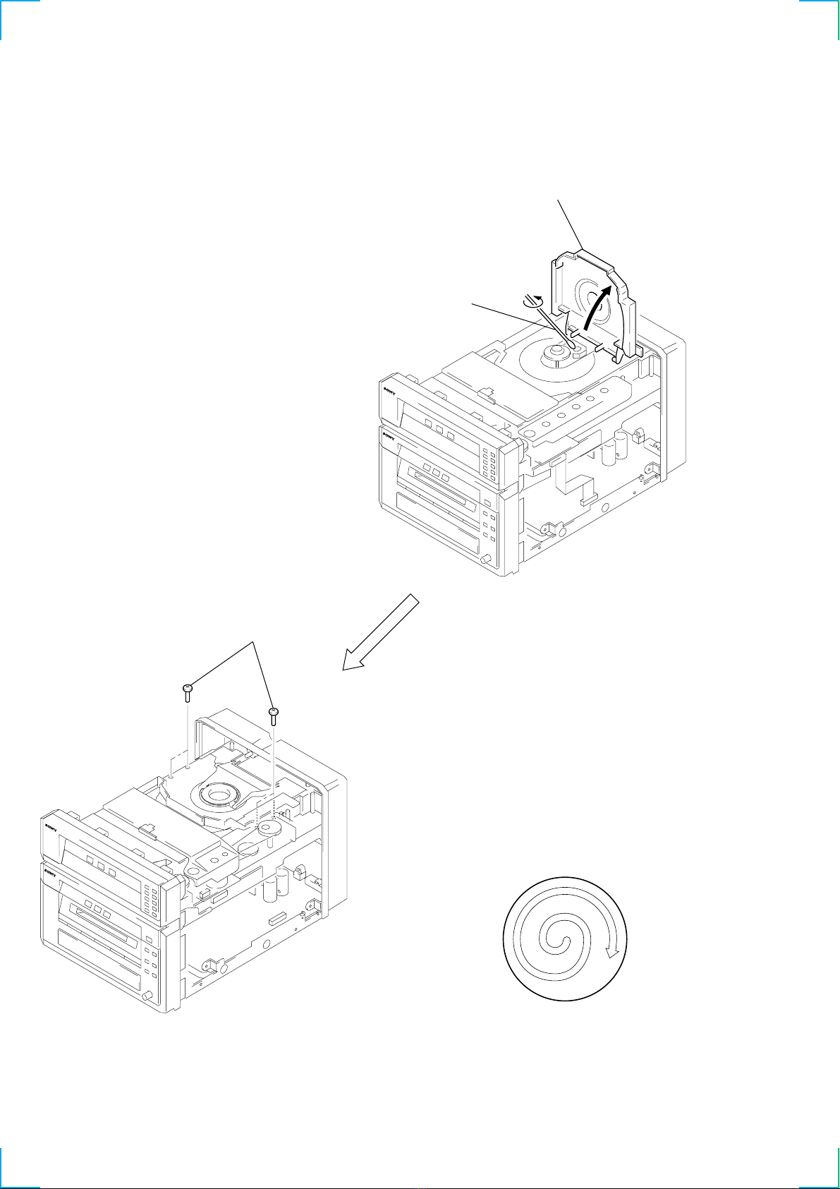
3. DISASSEMBLY
3-1. Case ..................................................................................... 13
3-2. Front Panel Section ............................................................. 13
3-3. CD Mechanism Deck Section ............................................. 14
3-4. MD Mechanism Deck Block ............................................... 14
3-5. CD Base Unit ...................................................................... 15
3-6. Main Board ......................................................................... 15
3-7. Fitting Base (Guide) Assy, Bracket (Chassis) and
Magnet Assy ....................................................................... 16
3-8. Tray (Sub) ........................................................................... 16
3-9. Chassis (Mold B) Section, Stocker Section and
Slider (Selection) ................................................................ 17
3-10. Gears Installation .............................................................. 17
3-11. Slider (Selection) Installation ............................................ 18
3-12. Stocker Section Installation............................................... 18
3-13. Chassis (Mold B) Section Installation .............................. 19
3-14. MD Mechanism Deck Section .......................................... 19
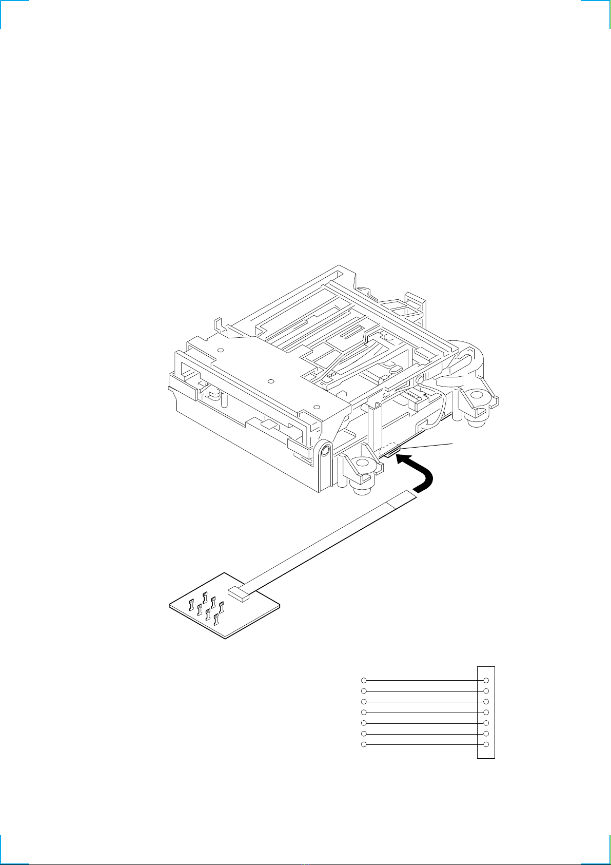
3-15. BD (MD) Board ................................................................ 20
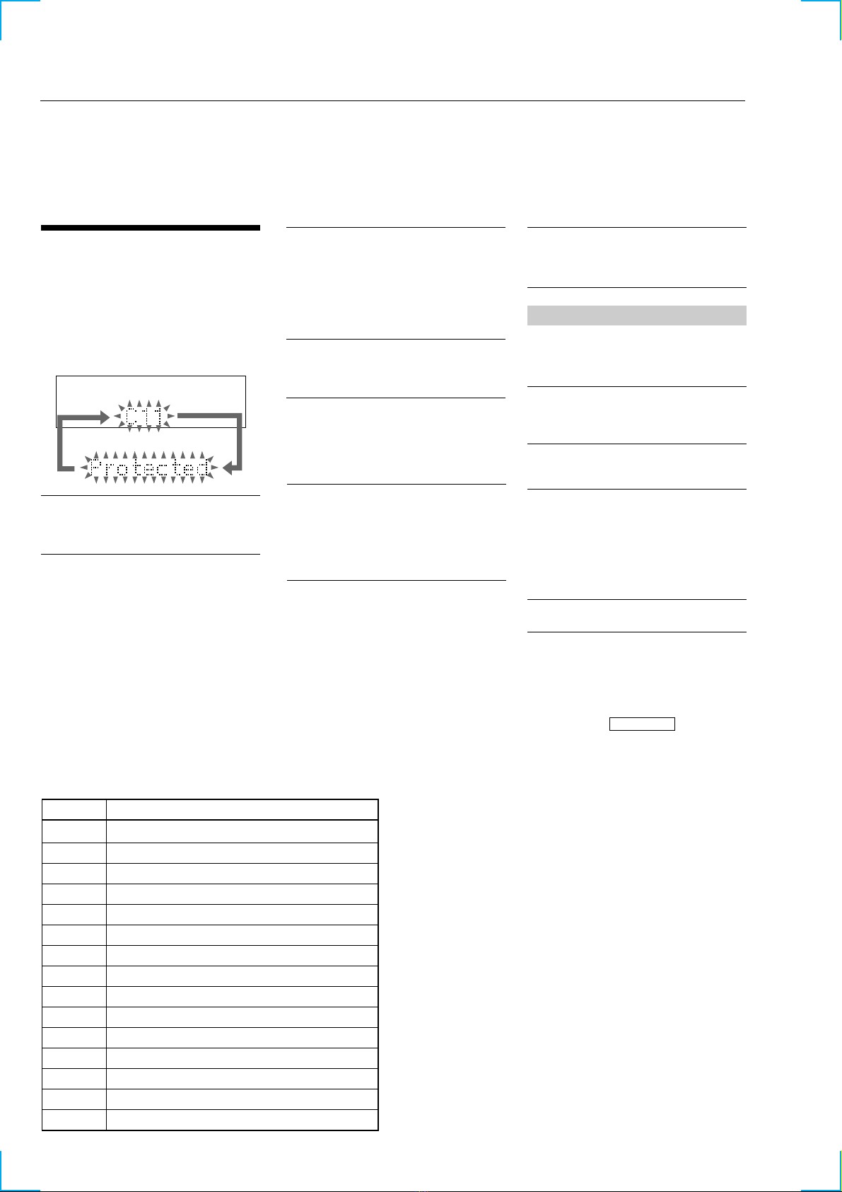
4. TEST MODE ...................................................................... 21
5. ELECTRICAL ADJUSTMENT.................................... 27
6. DIAGRAMS
6-1. Circuit Boards Location ...................................................... 39
6-2. Block Diagrams ................................................................... 41
6-3. Schematic Diagram –CD Section –.................................... 44
6-4. Printed Wiring Board –CD Section –................................. 45
6-5. Printed Wiring Board –MD Section –................................ 46
6-6. Schematic Diagram –MD Section (1/2) –.......................... 47
6-7. Schematic Diagram –MD Section (2/2) –.......................... 48
6-8. Schematic Diagram –Main Section (1/2) –........................ 49
6-9. Schematic Diagram –Main Section (2/2) –........................ 50
6-10. Printed Wiring Board –Main Section –............................ 51
6-11. Schematic Diagram –Digital Section –............................ 52
6-12. Printed Wiring Board –Digital Section –......................... 53
6-13. Schematic Diagram –Panel Section –.............................. 54
6-14. Printed Wiring Board –Panel Section –............................ 55
6-15. Schematic Diagram –CD Mechanism Section –.............. 56
6-16. Printed Wiring Board –CD Mechanism Section –........... 57
6-17. IC Block Diagrams ............................................................ 58
6-18. IC Pin Function ................................................................. 62
7. EXPLODED VIEW
7-1. Case, Chassis Section ......................................................... 71
7-2. Front Panel Section ............................................................. 72
7-3. CD Mechanism Deck Section-1.......................................... 73
7-4. CD Mechanism Deck Section-2.......................................... 74
7-5. CD Base Unit Section ......................................................... 75
7-6. MD Mechanism Section-1 .................................................. 76
7-7. MD Mechanism Section-2 .................................................. 77
8. ELECTRICAL PARTS LIST ........................................ 78

5
POWER SUPPLY DURING SERVICING
• As this set has not own power supply, it does not operate indepen-
dently. Therefore, during servicing, connect it to the Pre-Main
amplifier and Tuner Unit (STR-NX5MD) of DHC-NX5MD.
If STR-NX5MD are not available, use the Power Feed Jig (PFJ-
1) and Relay Connector Jig.
In this case, after turn on the POWER switch on the Power Feed
Jig, supply power with the following methods.
Procedure:
1. Press three buttons of G(MD), A(DISC 1), and s(CD)
simultaneously.
Set
SYSTEM CONTROL termina
l
SYSTEM CONTROL terminal
Connector cable (19P)
Pre-Main AMP
and Tuner Unit
AC IN
Power feed jig
(PFJ-1)
Connector cable (17P) of
attachment to power feed jig
Relay connector jig
(J-2501-197-A)
CN101 (19P)
SYSTEM CONTROL
terminal
system cable
Exclusive cable (15P)
P707, P909 Set
CDP/MD
ST
Connection:
function button
CD AMS – AMS –
AMS + AMS +
FR m
FF M
MD AMS – AMS –
AMS + AMS +
FR m
FF M

6
Note 1: In cleaning the lens, do not apply an excessive force.
As the optical pick-up is vulnerable, application of excessive
force could damage the lens holder.
Note 2: In cleaning, do not use a cleaner other than exclusive clean-
ing liquid (KK-91 or isopropyl alcohol).
Note 3: Wipe the objective lens spirally from center toward outside.
(See Figure A)
OPTICAL PICK-UP CLEANING
1
Remove the case. (Refer to disassembly page 13)
2four screws
(BVTP M2.6)
3Open the magnet
assy.
4Cleaning the
optical pick-up.
(Figure A)

7
JIG FOR CHECKING BD (MD) BOARD WAVEFORM
The special jig (J-2501-196-A) is useful for checking the waveform of the BD (MD) board. The names of terminals and the checking items
to be performed are shown as follows.
GND : Ground
I+3V : For measuring IOP (Check the deterioration of the optical pick-up laser)
IOP : For measuring IOP (Check the deterioration of the optical pick-up laser)
TE : TRK error signal (Traverse adjustment)
VC : Reference level for checking the signal
RF : RF signal (Check jitter)
FE : Focus error signal
I+3V
IOP
GND
TE
FE
VC
RF
I+3V
IOP
GND
TE
FE
VC
RF
1
7
for
MDM-7B
I+3V
CN105
IOP
TE
VC
GND
FE RF

8
Iop DATA RECORDING AND DISPLAY WHEN OPTICAL PICK-UP AND NON-VOLATILE MEMORY (IC195 OF
BD BOARD) ARE REPLACED
The Iop value labeled on the optical pick-up can be recorded in the non-volatile memory. By recording the value, it will eliminate the need
to look at the value on the label of the optical pick-up. When replacing the optical pick-up or non-volatile memory (IC195 of BD board),
record the Iop value on the optical pick-up according to the following procedure.
Record Precedure:
1. Clicking the ENTER/YES button and the A(DISC 5) button while clicking the m(MD) button causes the program to enter test mode
and the message “Check”to be displayed on screen.
2. Rotate the MD JOG knob to display “[Service]”, and press the ENTER/YES button.
3. Rotate the MD JOG knob to display “Iop Write”(C05), and press the ENTER/YES button.
4. The display becomes “Ref=@@@.@”(@ is an arbitrary number) and the numbers which can be changed will blink.
5. Input the Iop value written on the optical pick-up.
To select the number : Rotate the MD JOG knob.
To select the digit : Press the MD JOG knob.
6. When the ENTER/YES button is pressed, the display becomes “Measu=@@@.@”(@ is an arbitrary number).
7. As the adjustment results are recorded for the 6 value. Leave it as it is and press the ENTER/YES button.
8. “Complete!”will be displayed momentarily. The value will be recorded in the non-volatile memory and the display will become “Iop
Write”(C05).
9. Press the STR REPEAT button to complete.
Display Precedure:
1. Clicking the ENTER/YES button and the A(DISC 5) button while clicking the m(MD) button causes the program to enter test mode
and the message “Check”to be displayed on screen.
2. Rotate the MD JOG knob to display “[Service]”, and press the ENTER/YES button.
3. Rotate the MD JOG knob to display “Iop Read”(C26).
4. “@@.@/##.#”is displayed and the recorded contents are displayed.
@@.@ : indicates the Iop value labeled on the pick-up.
##.# : indicates the Iop value after adjustment
5. To end, press the MD JOG button or MENU/NO button to display “Iop Read”(C26). Then press the REPEAT button.

9
CHECKS PRIOR TO PARTS REPLACEMENT AND ADJUSTMENTS
Before performing repairs, perform the following checks to determine the faulty locations up to a certain extent.
Details of the procedures are described in “5 Electrical Adjustments”.
•5-6-2. Laser power check (see page 31)
•5-6-3. Iop Compare (see page 31)
•5-6-4. Auto Check (see page 32)
Note:
The criteria for determination above is intended merely to determine if satisfactory or not, and does not serve as the specified value for
adjustments.
When performing adjustments, use the specified values for adjustments.

10
Fig. 2 Reading the Test Mode Display
(During playback)
@@####**$$
Fluorescent display tube display
@@ : Parts No. (name of area named on TOC)
## : Cluster
** : Sector
$$ : Track mode (Track information such as copyright infor-
mation of each part)
RETRY CAUSE DISPLAY MODE
•In this test mode, the causes for retry of the unit during recording can be displayed on the fluorescent indicator tube. During playback, the
“track mode”for obtaining track information will be set.
This is useful for locating the faulty part of the unit.
•The following will be displayed :
During recording and stop : Retry cause, number of retries, and number of retry errors.
During playback : Information such as type of disc played, part played, copyright.
These are displayed in hexadecimal.
Procedure:
1. Press the ENTER/YES button while pressing the A(DISC 5) button and NAME EDIT/CHARACTER button.
2. Press the REC/RECIT button to start recording. Then press the Xbutton and start recording.
3. To check the “track mode”, press the Hbutton to start play.
4. To exit the test mode, press the @/1 button, and turn OFF the power. When “TOC”disappears, disconnect the power plug from the outlet.
} Address (Physical address on disc)
Hexadecimal
Bit
Binary
Higher Bits Lower Bits
84218421
b7 b6 b5 b4 b3 b2 b1 b0
00000001
00000010
00000100
00001000
00010000
00100000
01000000
10000000
When track jump (shock) is detected
When ADER was counted more than five times continu-
ously
When ADIP address is not continuous
When DIN unlock is detected
When not in focus
When ABCD signal level exceeds the specified range
When CLV is unlocked
When access operation is not performed normally
Hexa-
decimal
shock
ader5
Discontinuous address
DIN unlock
FCS incorrect
IVR rec error
CLV unlock
Access fault
Cause of Retry Occurring conditions
01
02
04
08
10
20
40
80
Fig. 1 Reading the Test Mode Display
(During recording and stop)
RTs@@c##c***
Fluorescent display tube display
@@ : Cause of retry
## : Number of retries
*** : Number of retry errors
Reading the Display:
Convert the hexadecimal display into binary display. If more than two causes, they will be added.
Example
When 42 is displayed:
Higher bit : 4 = 0100 tb6
Lower bit : 2 = 0010 tb1
In this case, the retry cause is combined of “CLV unlock”and “ader5”.
When A2 is displayed:
Higher bit : A = 1010 tb7+b5
Lower bit : 2 = 0010 tb1
The retry cause in this case is combined of “Access fault”, “IVR rec error”, and “ader5”.
Reading the Retry Cause Display

11
Hexadecimal
Bit
Binary
Higher Bits Lower Bits
84218421
b7 b6 b5 b4 b3 b2 b1 b0
00000001
00000010
00000100
00001000
00010000
00100000
01000000
10000000
Hexa-
decimal
Details
01
02
04
08
10
20
40
80
Emphasis OFF
Monaural
This is 2-bit display. Normally 01.
01:Normal audio. Others:Invalid
Audio (Normal)
Original
Copyright
Write prohibited
When 0 When 1
Emphasis ON
Stereo
Invalid
Digital copy
No copyright
Write allowed
Reading the Display:
Convert the hexadecimal display into binary display. If more than two causes, they will be added.
Example When 84 is displayed:
Higher bit : 8 = 1000 tb7
Lower bit : 4 = 0100 tb2
In this case, as b2 and b7 are 1 and others are 0, it can be determined that the retry cause is combined of “Emphasis OFF”, “Monaural”,
“Original”, “Copyright exists”, and “Write allowed”.
Example When 07 is displayed:
Higher bit : 0 = 1000 tAll 0
Lower bit : 7 = 0111 tb0+b1+b2
In this case, as b0, b1, and b2 are 1 and others are 0, it can be determined that the retry cause is combined of “Emphasis ON”, “Stereo”,
“Original”, “Copyright exists”, and “Write prohibited”.
Hexadecimal
t
Binary Conversion Table
Hexadecimal Binary Hexadecimal Binary
0
1
2
3
4
5
6
7
8
9
A
B
C
D
E
F
0000
0001
0010
0011
0100
0101
0110
0111
1000
1001
1010
1011
1100
1101
1110
1111
Reading the Track Mode Display

12
SECTION 2
GENERAL
• LOCATION OF CONTROLS
– Front Panel –
1G(CD) button
2S(CD) button
3s(CD) button
4DISC 1 to 5 (CD) button and indicator
5A(CD DISC 1 to 5) button
6A(MD) button
7m(MD) button
8M(MD) button
9NAME EDIT/CHARACTER button
q; CLEAR button
qa MENU/NO button
qs ENTER/YES button
qd .MD JOG >+/– dial
qf S.F EDIT button
qg REC MODE button
qh HIGH SPEED button
qj Display window
qk NORMAL button
ql REC/REC IT button
w; MD DISPLAY button
wa MD disc compartment
ws G(MD) button
wd S(MD) button
wf s(MD) button
wg CD disc tray
wa
wg
1 2 345
qdqfqgqhqjqkqlw;
7
8
qa
6
9
wd
wf
ws
q;
qs

13
3-1. CASE
3-2. FRONT PANEL SECTION
Note: Follow the disassembly procedure in the numerical order given.
SECTION 3
DISASSEMBLY
1screw
(BVTP3 ×10)
2two screws
(case 3 TP2)
2two screws
(case 3 TP2)
3Remove the case
in the arrow A
direction.
A
3two screws
(SUMITITE (B3), +BV)
5screw
(BVTP3 ×10)
4screw
(BVTP2.6 ×8
)
4screw
(BVTP2.6 ×8)
6two screws
(BVTP3 ×10)
1flat cable (13 core)
(CN103)
2flat cable (9 core)
(CN102)
7front panel
section

14
3-3. CD MECHANISM DECK SECTION
(CDM53E-K4BD40)
3-4. MD MECHANISM DECK BLOCK
4four screws
(BVTP3 ×10)
1flat cable (17 core)
(CN112)
5Remove the CD mechanism deck
section (CDM53E-K4BD40) in
the arrow Adirection.
2flat cable (19 core)
(CN111)
3connector
(CN713)
A
2screw
(BVTP3 ×8)
3MD mechanism
deck block
1flat cable (25 core
)
(CN114)

15
3-5. CD BASE UNIT
(BU-K4BD40)
3-6. MAIN BOARD
4CD base unit
(BU-K4BD40)
2two compression spring
s
(silver)
1two screws
(PTPWH M2.6)
1two screws
(PTPWH M2.6)
3two compression springs
(black)
3screw
(BVTP3 ×10)
1screw
(BVTP3 ×10
)
4three screws
(BVTP3 ×8)
6Remove the MAIN board
in the arrow Adirection.
2connection cord
(CN101)
A
5two PC board
holders

16
3-7. FITTING BASE (GUIDE) ASSY, BRACKET (CHASSIS) AND
MAGNET ASSY
3-8. TRAY (SUB)
7four screws
(BVTP M2.6)
2four screws
(BVTP M2.6)
5bracket
(chassis)
4five screws
(BVTP M2.6) 6connector
(CN710)
1two connectors
(CN709, 715)
8base (magnet) assy, fitting
3base
(guide) assy, fitting
pulley (LD)
stocker
section
tray (sub)
pulley (mode)
slider (selection)
1Rotating the pulley (LD), shift the slider (selection) in the arrow Adirection.
2Rotating the pulley (mode) in the arrow direction, adjust the tray (sub) to be removed.
3Rotating the pulley (LD), shift the slider (selection) in the arrow Bdirection.
4Rotating the pulley (mode) in the arrow direction, remove the tray (sub) to be removed.
A
B

17
3-9. CHASSIS (MOLD B) SECTION, STOCKER SECTION AND
SLIDER (SELECTION)
Note: In mounting the parts, refer to page 18 and 19.
3-10. GEARS INSTALLATION
5stocker
section
4two step
screws
4two step screws 3gear (eject)
2chassis (mold B) section
Note: Rotating the pulley (LD),
shift the slider (selection)
to the left.
9compression
spring
7slider (selection)
8washer
6two screws
(PTPWH M2.6)
1three screws
(BVTP M2.6)
pulley (LD)
1Slide the slider (U/D)
fully in the arrow
direction.
3gear (gear B)
2gear (U/D slider)
4gear (gear A)
Adjust the gear (gear B) with the
portion A as shown.
Adjust the gear so that it meshes with
the bottom tooth of slider (U/D)gear,
as shown.
portion A
slider (U/D) gear linearly
gear
(gear B)
Adjust so as to be aligned with
gear (B) linearly,as shown.

18
3-11. SLIDER (SELECTION) INSTALLATION
3-12. STOCKER SECTION INSTALLATION
portion A
2gear (chuking)
6two screws
(PTPWH M2.6)
5washer
3convex portion of
slider (selection)
4compression spring
7Insert the slider (selection)
into the portion A.
1rotary encoder
rotary encoder
Align with the slot of
rotary encoder.
align marking
gear (chuking)
Insert a convex portion into
a groove of gear (chuking).
2portion A of tray (sub)
1stocker section
3two step screws
3two step screws
Hook the portion A of tray (sub)
to the slider (selection).
potion A
of tray (sub) sticking of
slider (selection)

19
3-13. CHASSIS (MOLD B) SECTION INSTALLATION
3-14. MD MECHANISM DECK SECTION
(MDM-7B)
3three screws
(BVTP M2.6)
2Insert the gear (eject)
under the gear (LD
deceleration).
1Insert the portion A of
chassis (mold B) sectio
n
into the portion B of
slider (selection).
gear (LD deceleration)
portion A
portion B of
slider (selection)
1two screws
(BVTP 3 ×8)
2screw
(BVTP 3 ×8)
3cover (MD)
qa two screws
(BVTPWH M3), step
0two screws
(BVTPWH M3), step
qs MD mechanism deck
(MDM-7B)
7two claws
8DIGITAL board
6screw
(BVTP 3 ×8)
4flat type wire (17core)
(CN1004)
5flat type wire (27core)
(CN1003)
9flat type wire (25core)
(CN1001)
A
A

20
3-15. BD (MD) BOARD
M102
M101
M103
S102
2Remove the solder
(Two portions)
2Remove the solder
(Two portions)
2Remove the solder
(Two portions)
2Remove the solder
(Three portions)
1connector
(CN104)
6connector
(CN101)
3two screws
(BTP 2 ×6) 4BD (MD) board
5Connect the short land
by lead wire.
short land
Bottom of the optical pick-up
CN101
Table of contents
Other Sony Stereo System manuals

Sony
Sony SRS-X99 User manual

Sony
Sony MHC-M80D User manual

Sony
Sony MEXBT5700U - CD Receiver Bluetooth... User manual

Sony
Sony MHC-V11 User manual

Sony
Sony SHAKE-X30 User manual

Sony
Sony MHC-GX99 User manual

Sony
Sony HCD-CP333 User manual

Sony
Sony SEN-211 User manual

Sony
Sony FST-ZX100D User manual

Sony
Sony CDP-C221 User manual

Sony
Sony MHC-GN900 User manual

Sony
Sony HCD-DR8AV User manual

Sony
Sony HCD-S3000 User manual

Sony
Sony HCD-MD595 User manual

Sony
Sony LBT-D107 User manual

Sony
Sony LBT-XGR600 - Compact Hi-fi Stereo System User manual

Sony
Sony SRS-ZR5 User manual

Sony
Sony SRS-XB3 User manual

Sony
Sony CMT-WS2D User manual

Sony
Sony ZS-X1 - Cd Boombox User manual