Sony MHC-V42D User manual

SERVICE MANUAL
Sony Corporation
Published by Sony EMCS (Malaysia) PG Tec
AEP Model
UK Model
E Model
Australian Model
MHC-V42D
HOME AUDIO SYSTEM
9-930-602-01
2019B81-1
© 2019.02
Ver. 1.0 2019.02
SPECIFICATIONS
Model Name Using Similar Mechanism MHC-V41D
DVD Mechanism Type CDM90-DVBU204//C
Optical Pick-up Name CMS-S76RFS7GP
Note:
Be sure to keep your PC used for service and
checking of this unit always updated with the
latest version of your anti-virus software.
In case a virus affected unit was found during
service, contact your Service Headquarters.
– Continued on next page –
Speaker section
Speaker system:
3-way, Double Bass Reflex
Speaker unit:
Tweeter L/R: 40 mm
, cone type
Midrange L/R: 80 mm, cone type
Woofer: 250 mm, cone type
Inputs
AUDIO/PARTY CHAIN IN (TV) L/R:
Voltage 2 V, impedance 47 kilohms
TV (ARC):
Supported audio signal:
2-channel Linear PCM
MIC1:
Sensitivity 1 mV, impedance 10 kilohms
MIC2/GUITAR:
Sensitivity 1 mV, impedance
10 kilohms (When guitar mode is
turned off.)
Sensitivity 200 mV, impedance
1 Megaohm (When guitar mode is
turned on.)
Outputs
AUDIO/PARTY CHAIN OUT L/R:
Voltage 2 V, impedance 1 kilohm
HDMI OUT (TV) ARC:
Supported audio signal:
2-channel Linear PCM (up to 48 kHz),
Dolby Digital
HDMI section
Connector:
Type A (19 pin)
Disc player section
System:
Compact disc and digital audio and
video system
Laser Diode Properties
Emission Duration: Continuous
LaserOutput*:Lessthan44.6μW
* This output is the value measure-
ment at a distance of 200 mm from
the objective lens surface on the
Optical Pick-up Block with 7 mm
aperture.
Frequency response:
20 Hz – 20 kHz
Video color system format:
Latin American models:
NTSC
Other models:
NTSC and PAL
USB section
Supported USB device:
Mass Storage Class
Maximum current:
1 A
(USB) port:
Type A
FM tuner section (except AEP, UK)
FM stereo, FM superheterodyne tuner
Antenna:
FM lead antenna
Tuning range:
87.5 MHz – 108.0 MHz (50 kHz step)
BLUETOOTH section
Communication system:
BLUETOOTH Standard version 4.2
Output:
BLUETOOTH Standard Power
Class 2
Maximum output power:
< 9.5 dBm
Maximum number of devices to be
registered:
8 devices
Maximum number of simultaneous
connection (Multipoint):
3 devices
Maximum communication range:
Line of sight approx. 10 m1)
Frequency band:
2.4 GHz band (2.4000 GHz –
2.4835 GHz)
Modulation method:
FHSS (Freq Hopping Spread
Spectrum)
Compatible BLUETOOTH profiles2):
A2DP (Advanced Audio
Distribution Profile)
AVRCP (Audio Video Remote
Control Profile)
SPP (Serial Port Profile)
Supported codecs:
SBC (Subband Codec)
AAC (Advanced Audio Coding)
LDAC
1) The actual range will vary depending on
factors such as obstacles between devices,
magnetic fields around a microwave oven,
static electricity, reception sensitivity,
antenna’s performance, operating system,
software application, etc.
2) BLUETOOTH standard profiles indicate
the purpose of BLUETOOTH communica-
tion between devices.
NFC section
Frequency band:
13.56 MHz
Supported audio formats
Supported bit rate and sampling frequencies:
MP3:
32/44.1/48 kHz, 32 kbps –
320 kbps (VBR)
AAC:
44.1 kHz, 48 kbps – 320 kbps
(CBR/VBR)
WMA:
44.1 kHz, 48 kbps – 192 kbps
(CBR/VBR)
WAV:
44.1/48 kHz (16 bit)
Supported video formats
Xvid:
Video codec: Xvid video
Bit rate: 4.854 Mbps (MAX)
Resolution/Frame rate:
720 × 480, 30 fps
720 × 576, 25 fps (except for Latin
American models)
Audio codec: MP3
MPEG4:
File format: MP4 File Format
Video codec: MPEG4 Simple
Prole(AVCisnotcompatible.)
Bit rate: 4 Mbps
Resolution/Frame rate:
720 × 480, 30 fps
720 × 576, 25 fps (except for Latin
American models)
Audio codec: AAC-LC (HE-AAC is
not compatible.)
DRM: Not compatible
General
Power requirements:
AC 120 V – 240 V, 50/60 Hz
Power consumption:
115 W
Power consumption (at the Power Saving
mode):
0.5 W (When “BT STBY” is set to
“OFF” and [CONTROL FOR
HDMI] is set to [OFF].)
2 W* (When “BT STBY” is set to
“ON” and [CONTROL FOR HDMI]
is set to [ON].)
Dimensions (W/H/D) (Approx.):
328 mm × 799 mm × 300 mm
Mass (Approx.):
12.6 kg
Operating temperature:
5 °C to 35 °C
* The power consumption of the system will
be less than 0.5 W when there is no HDMI
connection and “BT STBY” is set to “OFF”.
Design and specifications are subject to
change without notice.
SYSSET
2019/03/0500:47:46(GMT+09:00)

MHC-V42D
2
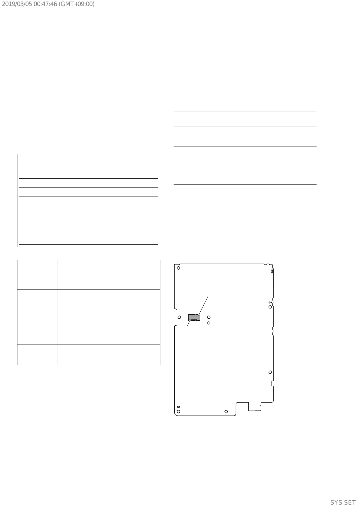
SAFETY-RELATED COMPONENT WARNING!
COMPONENTS IDENTIFIED BY MARK 0OR DOTTED LINE
WITH MARK 0ON THE SCHEMATIC DIAGRAMS AND IN
THE PARTS LIST ARE CRITICAL TO SAFE OPERATION.
REPLACE THESE COMPONENTS WITH SONY PARTS
WHOSE PART NUMBERS APPEAR AS SHOWN IN THIS
MANUAL OR IN SUPPLEMENTS PUBLISHED BY SONY.
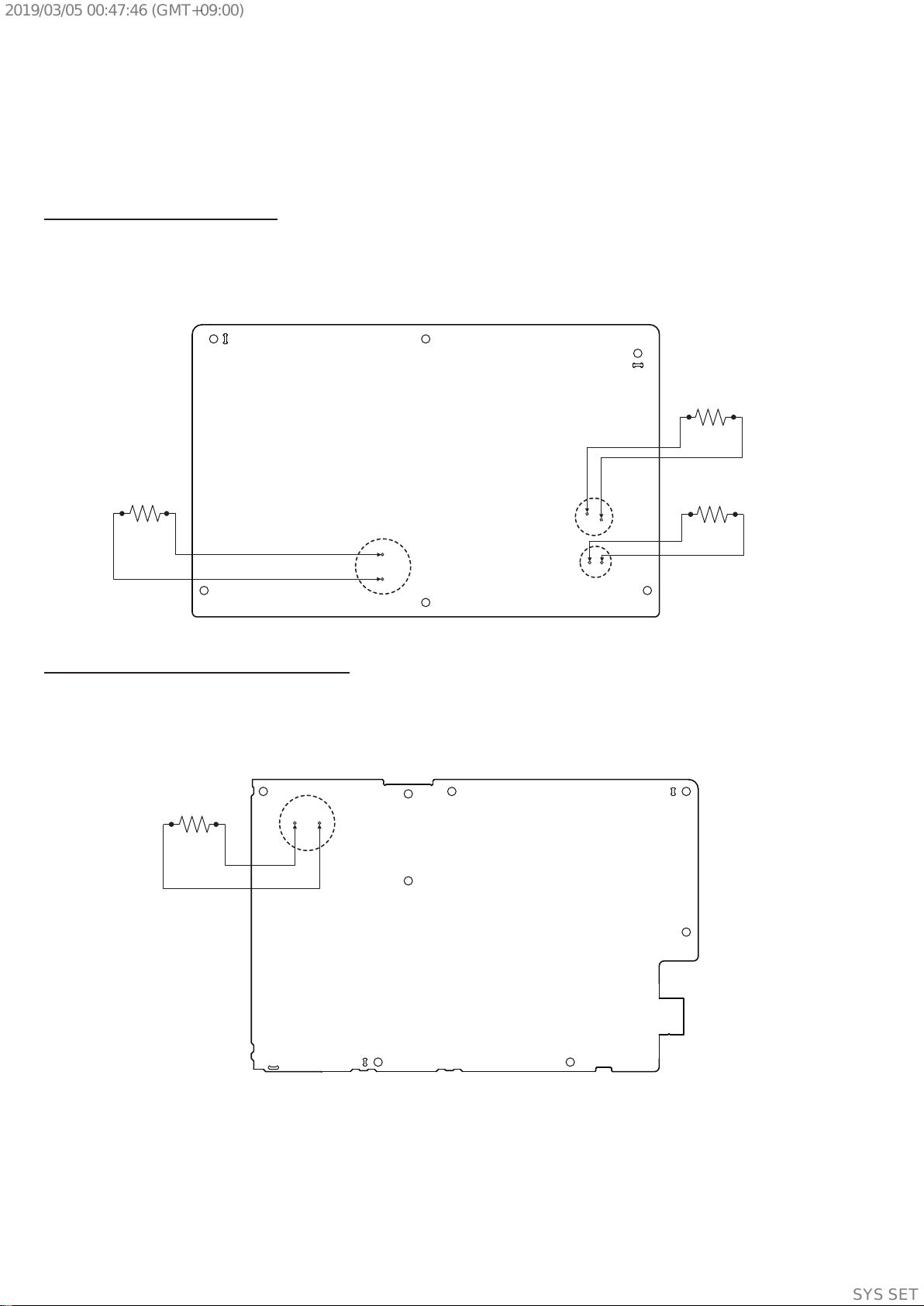
1.5 kΩ0.15 µF
AC
voltmeter
(0.75 V)
To Exposed Metal
Parts on Set
Earth Ground
Fig. A. Using an AC voltmeter to check AC leakage.
NOTES ON CHIP COMPONENT REPLACEMENT
• Neverreuseadisconnectedchipcomponent.
• Noticethattheminussideofatantalumcapacitormaybe
damaged by heat.
FLEXIBLE CIRCUIT BOARD REPAIRING
• Keepthetemperatureofthesolderingironaround270°C
during repairing.
• Donottouchthesolderingirononthesameconductorofthe
circuit board (within 3 times).
• Becarefulnottoapplyforceontheconductorwhensoldering
or unsoldering.
SAFETY CHECK-OUT
After correcting the original service problem, perform the following
safety check before releasing the set to the customer:
Check the antenna terminals, metal trim, “metallized” knobs,
screws, and all other exposed metal parts for AC leakage. Check
leakage as described below.
LEAKAGE TEST
The AC leakage from any exposed metal part to earth ground and
from all exposed metal parts to any exposed metal part having a
return to chassis, must not exceed 0.5 mA (500 microamperes).
Leakage current can be measured by any one of three methods.
1. A commercial leakage tester, such as the Simpson 229 or RCA
WT-540A. Follow the manufacturers’ instructions to use these
instruments.
2. A battery-operated AC milliammeter. The Data Precision 245
digital multimeter is suitable for this job.
3. Measuring the voltage drop across a resistor by means of a
VOM or battery-operated AC voltmeter. The “limit” indication
is 0.75 V, so analog meters must have an accurate low-voltage
scale. The Simpson 250 and Sanwa SH-63Trd are examples
of a passive VOM that is suitable. Nearly all battery operated
digital multimeters that have a 2V AC range are suitable. (See
Fig. A)
Supplied accessories
Remote control (DC 3 V) (1)
R03 (DC 1.5 V) (size AAA) batteries (2)
FM lead antenna (aerial) (1)
AC power cord (mains lead) (1)
AC plug adaptor* (1) (supplied only for certain areas)
* This plug adaptor is not for the use in Chile, Paraguay
and Uruguay. Use this plug adaptor in the countries/
regions where it is necessary.
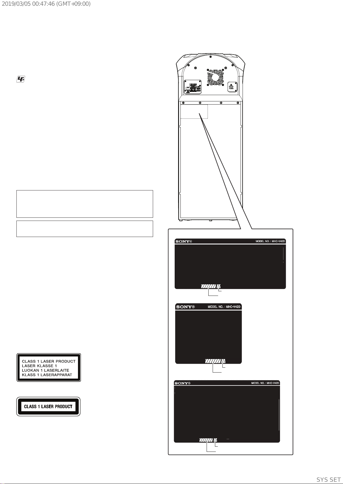
License and Trademark Notice
• is a trademark of DVD Format/Logo Licensing Corporation.
• “DVD+RW”, “DVD-RW”, “DVD+R”, “DVD-R”, “DVD VIDEO”,
and the “CD” logos are trademarks.
• WALKMAN®andWALKMAN®logo are registered trademarks
of Sony Corporation.
• MPEG Layer-3 audio coding technology and patents licensed from
Fraunhofer IIS and Thomson.
• Windows Media is either a registered trademark or trademark
of Microsoft Corporation in the United States and/or other
countries.
• Thisproductisprotectedbycertainintellectualpropertyrights
of Microsoft Corporation. Use or distribution of such technology
outside of this product is prohibited without a license from
Microsoft or an authorized Microsoft subsidiary.
• This system incorporates Dolby* Digital.
* Manufactured under license from Dolby Laboratories. Dolby,
Dolby Audio, and the double-D symbol are trademarks of Dolby
Laboratories.
• ThissystemincorporatesHigh-DefinitionMultimediaInterface
(HDMI™) technology. The terms HDMI and HDMI High-
Definition Multimedia Interface, and the HDMI Logo are
trademarks or registered trademarks of HDMI Licensing
Administrator, Inc. in the United States and other countries.
• “BRAVIA”isatrademarkofSonyCorporation.
• LDAC™ and LDAC logo are trademarks of Sony Corporation.
•The BLUETOOTH®word mark and logos are registered trade-
marks owned by the Bluetooth SIG, Inc. and any use of such
marks by Sony Corporation is under license. Other trademarks
and trade names are those of their respective owners.
•The N-Mark is a trademark or registered trademark of NFC
Forum, Inc. in the United States and in other countries.
•Android, Google Play, and the Google Play logo are trademarks
of Google LLC.
•Apple, the Apple logo, iPhone, iPod, and iPod touch are trade-
marks of Apple Inc., registered in the U.S. and other countries.
App Store is a service mark of Apple Inc., registered in the U.S.
and other countries.
• UseoftheMadeforApplebadgemeansthat an accessoryhas
been designed to connect specifically to the Apple product(s)
identified in the badge, and has been certified by the developer
to meet Apple performance standards. Apple is not responsible
for the operation of this device or its compliance with safety and
regulatory standards.
• THIS PRODUCT IS LICENSED UNDER THE MPEG-4 VISUAL
PATENT PORTFOLIO LICENSE FOR THE PERSONAL AND
NON-COMMERCIAL USE OF A CONSUMER FOR
(i) ENCODING VIDEO IN COMPLIANCE WITH THE MPEG-4
VISUAL STANDARD (“MPEG-4 VIDEO”)
AND/OR
(ii)DECODING MPEG-4 VIDEO THAT WAS ENCODED BY
A CONSUMER ENGAGED IN A PERSONAL AND NON-
COMMERCIAL ACTIVITY AND/OR WAS OBTAINED FROM
A VIDEO PROVIDER LICENSED TO PROVIDE MPEG-4
VIDEO.
NO LICENSE IS GRANTED OR SHALL BE IMPLIED FOR ANY
OTHER USE. ADDITIONAL INFORMATION INCLUDING THAT
RELATING TO PROMOTIONAL, INTERNAL AND COMMER-
CIAL USES AND LICENSING MAY BE OBTAINED FROM MPEG
LA, L.L.C.
HTTP://WWW.MPEGLA.COM
• Allothertrademarksaretrademarksoftheirrespectiveowners.
• Inthismanual,™and®marks are not specified.
SYSSET
2019/03/0500:47:46(GMT+09:00)

MHC-V42D
3
1. SERVICING NOTES ............................................. 4
2. DISASSEMBLY
2-1. Disassembly Flow........................................................... 10
2-2. Side Panel (L), (R) .......................................................... 11
2-3. Top Panel Section ........................................................... 12
2-4. Loading Panel Assy ........................................................ 13
2-5. CDM Section .................................................................. 14
2-6. Service, Optical Device (7G), Flexible Flat Cable ......... 15
2-7. Rear Panel ....................................................................... 16
2-8. SMPS Board ................................................................... 17
2-9. MOTHERBOARD Board, Chassis Section.................... 18
2-10. Front Panel Section......................................................... 19
2-11. Loudspeaker 25cm (Woofer) (SP5) ................................ 20
2-12. Loudspeaker 8cm (Mid: L-CH) (SP1),
Loudspeaker 8cm (Mid: R-CH) (SP3)............................ 21
3. TEST MODE ............................................................ 22
4. ELECTRICAL CHECK ......................................... 23
5. TROUBLESHOOTING .......................................... 24
6. DIAGRAMS
6-1. Block Diagram - MAIN Section (1/2) -.......................... 31
6-2. Block Diagram - MAIN Section (2/2) -.......................... 32
6-3. Block Diagram - AMP Section -..................................... 33
6-4. Block Diagram - DVD, USB, HDMI Section - .............. 34
6-5. Block Diagram - LED DRIVER Section -...................... 35
6-6. Block Diagram
- PANEL, POWER SUPPLY Section (1/2) - .................. 36
6-7. Block Diagram
- PANEL, POWER SUPPLY Section (2/2) - .................. 37
6-8. Printed Wiring Board - MOTHERBOARD Board
(Component Side) -......................................................... 39
TABLE OF CONTENTS
6-9. Printed Wiring Board - MOTHERBOARD Board
(Conductor Side) - .......................................................... 40
6-10. Printed Wiring Board
- PANEL Board (Except MY, E12),
PANEL (PANA) Board (MY, E12) -............................... 41
6-11. Printed Wiring Board - GESTURE Board
(Component Side) -......................................................... 42
6-12. Printed Wiring Board - GESTURE Board
(Conductor Side) - .......................................................... 42
6-13. Printed Wiring Board
- SMPS Board (AR, TH, E12, LA9),
SMPS (EMC) Board
(AEP,UK,RU,MY,AUS,E4,E93)- ............................ 43
6-14. Printed Wiring Board
- MIC Board (AR, TH, E12, LA9),
MIC (EMC) Board
(AEP,UK,RU,MY,AUS,E4,E93)- ............................ 44
6-15. Printed Wiring Board - IR Board -.................................. 45
6-16. Printed Wiring Board - NFC Board -.............................. 45
6-17. Printed Wiring Board - SW LED Board -....................... 45
6-18. Printed Wiring Board - FL PARTY Board -.................... 46
6-19. Printed Wiring Board - FR PARTY Board - ................... 46
7. EXPLODED VIEWS
7-1. Side Panel (L), (R) .......................................................... 47
7-2. Top Panel Section ........................................................... 48
7-3. Loading Panel Section .................................................... 49
7-4. Rear Panel Section .......................................................... 50
7-5. Chassis Section ............................................................... 51
7-6. Front Panel Section......................................................... 52
7-7. Speaker Cabinet Section ................................................. 53
7-8. CDM Section .................................................................. 54
7-9. DVD Mechanism Section
(CDM90-DVBU204//C) ................................................. 55
8. ELECTRICAL PARTS LIST .............................. 56
Accessories are listed in the last part of the electrical parts list.
SYSSET
2019/03/0500:47:46(GMT+09:00)

MHC-V42D
4
SECTION 1
SERVICING NOTES
UNLEADED SOLDER
Boards requiring use of unleaded solder are printed with the
leadfree mark (LF) indicating the solder contains no lead.
(Caution: Some printed circuit boards may not come printed with
the lead free mark due to their particular size)
: LEAD FREE MARK
Unleaded solder has the following characteristics.
• Unleadedsoldermeltsatatemperatureabout40°Chigher
than ordinary solder.
Ordinary soldering irons can be used but the iron tip has to be
applied to the solder joint for a slightly longer time.
Soldering irons using a temperature regulator should be set to
about 350 °C.
Caution: The printed pattern (copper foil) may peel away if
the heated tip is applied for too long, so be careful!
• Strongviscosity
Unleadedsolderismoreviscous(sticky,lesspronetoow)
than ordinary solder so use caution not to let solder bridges
occur such as on IC pins, etc.
• Usablewithordinarysolder
It is best to use only unleaded solder but unleaded solder may
also be added to ordinary solder.
CAUTION
Use of controls or adjustments or performance of procedures
otherthanthosespeciedhereinmayresultinhazardousradiation
exposure.
NOTES ON HANDLING THE OPTICAL PICK-UP BLOCK
OR BASE UNIT
The laser diode in the optical pick-up block may suffer electrostatic
break-down because of the potential difference generated by the
charged electrostatic load, etc. on clothing and the human body.
During repair, pay attention to electrostatic break-down and also
use the procedure in the printed matter which is included in the
repair parts.
Theexibleboardiseasilydamagedandshouldbehandledwith
care.
NOTES ON LASER DIODE EMISSION CHECK
The laser beam on this model is concentrated so as to be focused
onthediscreectivesurface bythe objectivelens intheoptical
pickup block. Therefore, when checking the laser diode emission,
observe from more than 30 cm away from the objective lens.
CAUTION
The use of optical instruments with this product will increase eye
hazard.
For customers in AEP, UK
Thisapplianceisclassiedasa
CLASS 1 LASER product under
IEC 60825-1:2007 and IEC
60825-1:2014. This marking is
located on the rear exterior.
For customers in E93
Thisapplianceisclassiedasa
CLASS 1 LASER product under
IEC 60825-1:2007 and IEC
60825-1:2014.
This label is located on rear
surface of the product.
CAUTION
Risk of explosion if the battery is replaced by an incorrect type.
Do not expose batteries or appliances with battery-installed to
excessiveheat,suchassunshineandre.
MODEL IDENTIFICATION
MODEL NUMBER LABEL
– Rear View –
AEP, UK, RU, AR, E93, LA9, MY
TH
AUS, E12, E4
PART No.
Destination
PART No
.
Destination Code
PART No.
Destination
SYSSET
2019/03/0500:47:46(GMT+09:00)

MHC-V42D
5
Model Part No.
V42D : LA9 4-746-471-0[]
V42D : AUS 4-746-471-1[]
V42D : E4 4-746-471-2[]
V42D : MY 4-746-471-3[]
V42D : RU 4-746-471-4[]
V42D : AEP 4-747-633-0[]
V42D : AR 4-747-633-1[]
V42D : E12 4-747-633-3[]
V42D : E93 4-747-633-4[]
V42D : TH 4-747-633-5[]
V42D : UK 4-747-633-6[]
DESTINATION ABBREVIATIONS
The following abbreviations for model destinations are used in this
service manual.
• Abbreviation
AR : Argentina model
AUS : Australian model
E4 : African model
E12 : 220-240 V AC area in E model
E93 : 240 V AC area in E model
LA9 : Latin-American model
MY : Malaysia model
RU : Russian model
TH : Thai model
DESTINATION SETTING METHOD
The destination information isn’t written in the MOTHERBOARD
board for the service.
Therefore, when the MOTHERBOARD board is replaced, be sure
to perform the destination setting (Important work).
Note 1: The initial setting destination of the MOTHERBOARD board for
the service is temporary set as “LATIN”. The message “DEST
ERR” is displayed on the screen display panel.
Note 2: When distinguishing the destination of the product, refer to the
“MODEL IDENTIFICATION” on page 4.
Note 3: If destination setting isn’t performed, it is possibility to occur the
defect to each operation of this unit.
Note 4: Destination would be locked if it has been changed for 5 times.
Procedure:
1. Press two buttons of the [SOUND FIELD] and
[TUNING +>] simultaneously for 5 seconds during the
demo mode.
2. It enters the destination setting mode, the message
“D XXXXX” is displayed on the screen display panel.
Note 5:Ifthemessage“DESTLOCK”isdisplayedonthescreendisplay
panel, press the [N] button to release from this mode. Because
the destination is locked, and it cannot change the destination.
3. Press [ +] / [ ―] button to select the destination based on the
set’s country.
Screen
display
Destination
code
Country
“D ASIA”SP6, TH1 Southeast Asia countries
“D INDIA”E12 India
“D ME AFC”E3, E93, E4,
SA2, EA3
Middle East & Africa countries
“D OCEANI”AU1 Australia & New Zealand
“D JAPAN”J1 Japan
“D BRAZIL”BR1 Brazil
“D N AME”UC2, CA2 America & Canada
“D LATIN”LA9, AR2 Central & South America
countries (except Brazil)
“D RUSSIA”RU1 Russia & CIS countries
“D EUROPE”CEL,CEK Europe countries
(except CIS country)
4. Press [N]buttontoconrmtheselection.
5. “RESET” appears on the screen display panel. After that,
“SONY” appears on the screen display panel. The system
automatically turn on and off once. Please be sure that the
systemstayatdemomodenallybeforeswitchoffthepower
supply.
6. Mode in “MODEL, DESTINATION AND VERSION
DISPLAYMODE”onpage22againtoconrmonthemodel
& destination.
NOTE OF REPLACEMENT OF THE MS-476 BOARD
When the MS-476 board is defective, exchange the entire
CDM90 ASSY.
TEST DISCS
UsefollowingTESTDISCwhenthisunitconrmstheoperation
and checks it.
• ForCD
Part No. Description
3-702-101-01 DISC (YEDS-18), TEST
4-225-203-01 DISC (PATD-012), TEST
J-2501-307-A DISC (HLX-A1), TEST
• ForDVDSL(SingleLayer)
Part No. Description
J-6090-069-A DISC (HLX-503), TEST (NTSC)
J-6090-088-A DISC (HLX-504), TEST (NTSC)
J-2501-305-A DISC (HLX-513), TEST (NTSC)
J-6090-077-A DISC (HLX-506), TEST (PAL)
• ForDVDDL(DoubleLayer)
Part No. Description
J-6090-071-A DISC (HLX-501), TEST (NTSC)
J-6090-089-A DISC (HLX-505), TEST (NTSC)
J-2501-306-A DISC (HLX-514), TEST (NTSC)
J-6090-078-A DISC (HLX-507), TEST (PAL)
SYSSET
2019/03/0500:47:46(GMT+09:00)

MHC-V42D
6
RELEASING THE DISC TRAY LOCK
The disc tray lock function for the antitheft of an demonstration
disc in the store is equipped.
It can release the lock function in the following procedure.
Releasing Procedure:
1. Press [1] button to turn the power on.
2. Press [FUNCTION] button until the message “DVD/CD” is
displayed.
3. Press [MEGA BASS] and [VOCAL FADER] buttons
simultaneously and hold down for around 3 seconds.
4. Themessage“UNLOCKED”isdisplayedandthedisctrayis
unlocked.
Note: When “LOCKED”is displayed, the disc tray lock is not released by
turning power on/off with the [1]button.
IF ERROR CODE AND “CHECK MANUAL” FLASHES
ON THE DISPLAY
See the following table for the corrective action.
Error code Corrective action
“PROTECT2” Contact your nearest Sony dealer.
“PROTECT3”/
“PROTECT4”/
“PROTECT6”
Immediately unplug the AC power cord
(mains lead), and check if anything is
blocking the ventilation openings of the
unit. After you have checked and found no
problems, reconnect the AC power cord
(mains lead), and turn on the system. If the
issue persists, contact your nearest Sony
dealer.
Protect Type Description:
X (Error Code) Description
2 Defect of thermistor IC or charging circuit
used by SPM (Sound Pressure Management)
system.
3•Thereispossibilityofovercurrenthappenat
speaker output or speaker damage (shorted).
•UnusualheatupofAMPICbyimproperas-
sembly of heatsink or lack of thermal com-
pound.
•UndervoltageProtection(nosupplytoAMP
IC when power ON).
•DCappearsinSPterminalbydefectofAMP
IC.
4 or 6
•ThereispossibilityofDCFANisblockedor
damaged.
•Defect of DC FAN driver circuit.
SELF-DIAGNOSIS FUNCTION:
When the self-diagnosis function is activated, a service number
appears on the TV screen or the display.
The service number consists of an alphabet and numerals
(e.g. C 13 50). See the following table for the cause and
corrective action.
First 3
characters of
the service
number
Cause and corrective action
C 13 This disc is dirty.
•Cleanthediscwithasoftcloth.
C 31 The disc is not inserted correctly.
•Turnoffthesystem,thenturnitonagain.
Then re-insert the disc correctly.
E XX
(XX is a
number)
To prevent a malfunction, the system has
performed the self-diagnosis function.
•Contact your nearest Sony dealer or local au-
thorized Sony service facility and give the
5-character service number.
Example: E 61 10
NOTE OF REPLACING THE IC2002 ON THE MOTH-
ERBOARD BOARD AND THE MOTHERBOARD
MOUNTED PC BOARD
When IC2002 on the MOTHERBOARD board and the MOTH-
ERBOARD mounted pc board are replaced, it is necessary to
spread the compound between parts and heat sink. After that,
execute “3. IC and MOTHERBOARD board after repair checking
guide” (page 29).
Spreadthecompoundreferringtothegurebelow.
– MOTHERBOARD Board (Component Side) –
IC2002
compound
SYSSET
2019/03/0500:47:46(GMT+09:00)

MHC-V42D
7
HOW TO OPEN THE TRAY WHEN POWER SWITCH TURN OFF
Note 1: After the side panel and top panel are removed, this work is done.
Note 2: Please prepare the thin wire (clip etc. processed to the length of 5 cm or more).
2Insert the clip etc.
3
1Remove the side panel (L), (R), top panel section.
(Illustration of disassembly is omitted.)
hole
DVD mechanism
deck
Insert the clip etc. processed to the
length of 5 cm or more in the hole
on the side of the CDM and push.
Note: Push after it inserts it
in this hole well.
- Left view -
- Top view -
tray
5 cm or more
SYSSET
2019/03/0500:47:46(GMT+09:00)

MHC-V42D
8
CAPACITOR ELECTRICAL DISCHARGE PROCESSING
When removing the SMPS board and MOTHERBOARD board, be sure to perform the discharge process by referring below procedure.
RemoveSMPSboardrstfollowbyMOTHERBOARDboard.
Note: Be sure to discharge using a resistor of 500~800 Ω.
SMPS Board (Conductor side view)
1. Disconnect all the wires and FFC which connected to the SMPS board (avoid touching any component).
2. Unscrew the SMPS board.
3. Pulling up the wire (avoid touching any component) to lift up the SMPS board.
4. Flip the SMPS board to conductor side and perform discharge at terminal of C6302, C6558 and C6559 for 10 seconds each.
MOTHERBOARD Board (Conductor side view)
1. Disconnect all the wires and FFC which connected to the MOTHERBOARD board (avoid touching any component).
2. Unscrew the MOTHERBOARD board.
3. Holding the both edge (avoid touching any component) to lift up the MOTHERBOARD board.
4. Flip the MOTHERBOARD board to conductor side and perform discharge at terminal of C2076 for 90 seconds.
R
800 Ω/5 W
C2076
C6302
C6558
C6559
R
800 Ω/5 W
800 Ω/5 W
R
800 Ω/5 W
R
SYSSET
2019/03/0500:47:46(GMT+09:00)

MHC-V42D
9
SERVICE POSITION
top panel section
SMPS board
(AR, TH, E12, LA9),
SMPS (EMC) board
(AEP, UK, RU, MY, AUS, E4, E93)
stand
CDM90-DVBU204//C
GESTURE board
PANEL board
(EXCEPT MY, E12),
PANEL (PANA) board
(MY, E12)
MIC board
(AR, TH, E12, LA9),
MIC (EMC) board
(AEP, UK, RU, MY, AUS, E4, E93)
NFC board
SYSSET
2019/03/0500:47:46(GMT+09:00)

MHC-V42D
10
Note: Disassembletheunitintheorderasshownbelow.
2-1. DISASSEMBLY FLOW
SECTION 2
DISASSEMBLY
• JIG
When disassembling the unit, use the following jig for speaker
removal.
Part No. Description
J-2501-238-A JIG FOR SPEAKER REMOVAL
2-3. TOP PANEL SECTION
(Page 12)
2-2. SIDE PANEL (L), (R)
(Page 11)
2-5. CDM SECTION
(Page 14)
2-4.
LOADING PANEL ASSY
(Page 13)
2-8.
SMPS BOARD
(Page 17)
2-10.
FRONT PANEL SECTION
(Page 19)
2-6. SERVICE, OPTICAL
DEVICE (7G),
FLEXIBLE FLAT CABLE
(Page 15)
SET
2-7.
REAR PANEL
(Page 16)
2-9.
MOTHERBOARD BOARD,
CHASSIS SECTION
(Page 18)
2-11. LOUDSPEAKER 25CM (WOOFER)
(SP5)
(Page 20)
2-12. LOUDSPEAKER 8CM (MID: L-CH) (SP1),
LOUDSPEAKER 8CM (MID: R-CH) (SP3)
(Page 21)
SYSSET
2019/03/0500:47:46(GMT+09:00)

MHC-V42D
11
Note: Followthedisassemblyprocedureinthenumericalordergiven.
2-2. SIDE PANEL (L), (R)
1five screws
(+BVTP 3 ×8) (BLACK)
2Remove the panel, side (R)
in the direction of the arrow.
2Remove the panel, side (L)
in the direction of the arrow.
1five screws
(+BVTP 3 ×8) (BLACK)
panel, side (L)
panel, side (R)
3
3
SYSSET
2019/03/0500:47:46(GMT+09:00)

MHC-V42D
12
2-3. TOP PANEL SECTION
two claws
7three screws
(+BVTP 3 ×8) (BLACK)
8one screw
(+BVTP 3 ×8) (SILVER)
9Remove the panel, top section
in the direction of the arrow.
0
2flexible flat cable
(9 core) (CN902)
3flexible flat cable
(6 core) (CN105)
4flexible flat cable
(15 core) (CN103)
5flexible flat cable
(7 core) (CN120)
6CN451 (5P)
1one screw
(+BVTP 3 ×8) (SILVER)
8one screw
(+BVTP 3 ×8) (SILVER)
qa panel, top section
SYSSET
2019/03/0500:47:46(GMT+09:00)

MHC-V42D
13
2-4. LOADING PANEL ASSY
1Insert the clip etc. 2Draw out the tray.
tray
4panel, loading assy
hole
DVD mechanism
deck
Insert the clip etc. processed to the
length of 5 cm or more in the hole
on the side of the CDM and push.
5 cm or more
Note : Push after it inserts it
in this hole well.
- Left view -
- Top view -
tray
3three claws
SYSSET
2019/03/0500:47:46(GMT+09:00)

MHC-V42D
14
2-5. CDM SECTION
9four screws
(+BVTP 3 ×8) (SILVER)
1flexible flat cable
(24 core) (CN302)
3CN402 (4P)
5two screws
(+BVTP 3 ×8) (BLACK)
6two screws
(+BVTP 3 ×8) (SILVER)
8bracket, CDM
7Remove the CDM section
in the direction of the arrow.
2flexible flat cable
(5 core) (CN303)
0CDM90-DVBU204//C
• Wire setting
4Remove the wires and
FFC from the clip, coating.
clip, coating
front side
SYSSET
2019/03/0500:47:46(GMT+09:00)

MHC-V42D
15
2-6. SERVICE, OPTICAL DEVICE (7G), FLEXIBLE FLAT CABLE
Under the guide
Under the guide
(Fold area)
• Installation of flexible flat cable (24 core) and flexible flat cable (5 core)
Note: This illustration sees the loading assy (MB) from bottom side.
1flexible flat cable
(24 core)
2Through the hole
3Through the hole
4
terminal face
loading assy (MB)
7flexible flat cable
(24 core)
6holder, FFC
5three claws
5two claws
0flexible flat cable
(5 core)
9
8
filament tape
filament tape
7four insulator screws
9connector
qa insulator
6belt
3Insert the thin
wire (clip etc.).
5tray
qs service, optical
device (7G)
qa insulator
qa insulator
1
six claws
4
0
8
2chuck holder assy (MB)
qd base, lo assy
qj
ql flexible flat cable
(24 core)
qg flexible flat cable
(5 core)
qf filament tape
qh filament tape
– Bottom view –
loading assy (MB)
qk holder, FFC
SYSSET
2019/03/0500:47:46(GMT+09:00)

MHC-V42D
16
2-7. REAR PANEL
1CN2001 (2P)
2four screws
(3.5 ×14), TAPPING
4cap, service connector
3one screw
(+BVTP 3 ×8) (BLACK)
5seven screws
(+BVTP 3 ×8) (BLACK)
6Remove the panel, rear section
in the direction of the arrow.
7panel, rear section
SYSSET
2019/03/0500:47:46(GMT+09:00)

MHC-V42D
17
2-8. SMPS BOARD
- Rear view -
7Remove the SMPS
board in the direction
of the arrow.
1CN6500 (8P)
2CN001 (11P)
4six screws
(+PWH 3 ×8 (SUMITITE))
5clip, coating
6SMPS board
(AR, TH, E12, LA9)
SMPS (EMC) board
(AEP, UK, RU, MY, AUS, E4, E93)
clip, coating
• Wire setting
front side
3Remove the wires from the
clip, coating.
SYSSET
2019/03/0500:47:46(GMT+09:00)

MHC-V42D
18
2-9. MOTHERBOARD BOARD, CHASSIS SECTION
Note 1: When the MOTHERBOARD mounted pc board
is replaced, be sure to refer to “DESTINATION
SETTING METHOD” on page 5.
qg Remove the chassis in
the direction of the arrow.
- Rear view -
qs heat sink (MB-L)
When installing the heat sink (MB-L),
spread the compound referring to
“NOTE OF REPLACING THE IC2002
ON THE MOTHERBOARD BOARD
AND THE MOTHERBOARD
MOUNTED PC BOARD” on servicing
notes (page 6).
Note 2: 8six screws
(+BVTP 3 ×8) (SILVER)
9Remove the
MOTHERBOARD board
in the direction of the arrow.
0MOTHERBOARD board
qa two screws
(+BVTP 3 ×8)
(SILVER)
1CN2007 (8P)
2CN2021 (6P)
4CN2206 (8P)
5CN107 (2P)
6CN127 (3P)
qd four screws
(3.5 × 14), TAPPING
qf filament tape
qh chassis
claw
claw
7one screw
(M3)
• Wire setting
front side
chassis
filament tape
• Wire setting
chassis
3Remove the wires through
the chassis hole.
SYSSET
2019/03/0500:47:46(GMT+09:00)

MHC-V42D
19
2-10. FRONT PANEL SECTION
2Insert the jig into a space
and slowly remove the
panel, front section.
Note 1: When using a jig,
please work so as
not to injure panel,
front section and
speaker cabinet.
2Insert the jig into a space and slowly remove
the panel, front section.
Note 1: When using a jig, please work so as
not to injure panel, front section and
speaker cabinet.
2Insert the jig into a space and slowly remove the
panel, front section.
Note 1: When using a jig, please work so as
not to injure panel, front section and
speaker cabinet.
3All bosses are removed while moving
jig in the direction of the arrow and
panel, front section is removed.
4terminal
(narrow side)
[yellow/black]
5terminal
(narrow side)
[yellow/black]
5terminal
(wide side)
[yellow]
4terminal
(wide side)
[yellow]
3All bosses are removed
while moving jig in the
direction of the arrow and
panel, front section is
removed.
6Remove the panel, front
section in the direction of an arrow.
7panel, front section
total eighteen bosses
1two screws
(3.5 ×14), TAPPING
• Wire setting top side
Push the protrusion,
and remove the terminal
(wide side) [yellow].
Push the protrusion, and remove
the terminal (narrow side) [yellow/black].
loudspeaker
(4cm) (SP2)
• Wire setting top side
Push the protrusion,
and remove the terminal
(wide side) [yellow].
Push the protrusion, and remove
the terminal (narrow side) [yellow/black].
loudspeaker
(4cm) (SP4)
SYSSET
2019/03/0500:47:46(GMT+09:00)

MHC-V42D
20
2-11. LOUDSPEAKER 25CM (WOOFER) (SP5)
3terminal
(narrow side)
[grey/black]
3terminal
(wide side)
[grey]
1eight screws
(4 ×20), +BV TAPPING
4loudspeaker 25cm (woofer) (SP5)
2Remove the loudspeaker 25cm (woofer) (SP5)
in the direction of arrow.
terminal position
• Installation direction for the
loudspeaker 25cm (woofer) (SP5)
• Wire setting top side
Push the protrusion, and remove
the terminal (wide side) [grey].
Push the protrusion, and remove
the terminal (narrow side) [grey/black].
protrusion
SYSSET
2019/03/0500:47:46(GMT+09:00)
Other manuals for MHC-V42D
3
Table of contents
Other Sony Stereo System manuals

Sony
Sony SRS-X99 User manual

Sony
Sony HCD-ED2 - Compact Disc Deck Receiver User manual

Sony
Sony CX-J3000 User manual

Sony
Sony HCD-NXM2D User manual

Sony
Sony LBT-XB88KS User manual

Sony
Sony HCD-GPZ6 User manual

Sony
Sony HCD-RG222 User manual

Sony
Sony HCD-DV2D - Dvd / Reciever Component User manual

Sony
Sony SRS-XB2 User manual

Sony
Sony SEN-311CD User manual