Sony ZS-PS20CP User manual

SERVICE MANUAL
Sony Corporation
Audio&Video Business Group
Published by Sony Techno Create Corporation
ZS-PS20CP
SPECIFICATIONS
PERSONAL AUDIO SYSTEM
9-889-220-01
2008G04-1
© 2008.07
AEP Model
UK Model
Australian Model
Singapore Model
Korea Model
Thai Model
Ver. 1.0 2008.07
CD player section
System
Compact disc digital audio system
Laser diode properties
Emission duration: Continuous
Laser output: Less than 44.6 μW
(This output is the value measurement at a distance of
200mm from the objective lens surface on the
Optical Pick-up Block with 7mm aperture.)
Spindle speed
200 r/min (rpm) to 500 r/min (rpm) (CLV)
Number of channels
2
Frequency response
20 - 20 000 Hz +1/–2 dB
Wow and flutter
Below measurable limit
Radio section
Frequency range
FM: 87.5 - 108 MHz
AM: 531 - 1 611 kHz (9 kHz step)
530 - 1 610 kHz (10 kHz step)
Antennas
FM: Telescopic antenna
AM: Built-in ferrite bar antenna
USB section
Supported bit rate
MP3 (MPEG 1 Audio Layer-3):
32 - 320 kbps, VBR
WMA:
16-320Kbps,VBR
Sampling frequencies
MP3 (MPEG 1 Audio Layer-3):
32/44.1/48 kHz
WMA:
32/44.1/48kHz
(USB) port
USB-A (Full Speed)
General
Speaker
Full range: 8 cm (3 1/4 inches) dia., 4 Ω, cone type (2)
Input
(USB) port: Type A, maximum
current 500 mA
AUDIO IN jack (stereo minijack)
Outputs
Headphones jack (stereo minijack)
For 16 - 68 Ωimpedance headphones
Power output
1.7 W + 1.7 W (at 4 Ω, 10% harmonic distortion)
– Continued on next page –
CD
Section
Model Name Using Similar Mechanism ZS-S2iP
CD Mechanism Type KSM-213CDP
Optical Pick-up Name KSS-213C

ZS-PS20CP
2
SAFETY-RELATED COMPONET WARNING!
COMPONENTS IDENTIFIED BY MARK 0OR DOTTED LINE
WITH MARK 0ON THE SCHEMATIC DIAGRAMS AND IN
THE PARTS LIST ARE CRITICAL TO SAFE OPERATION.
REPLACE THESE COMPONENTS WITH SONY PARTS
WHOSE PART NUMBERS APPEAR AS SHOWN IN THIS
MANUAL OR IN SUPPLEMENTS PUBLISHED BY SONY.
Power requirements
For player:
Malaysia and Singapore models: 230 – 240 V AC, 50 Hz
Thailand model: 220 V AC, 50 Hz
Korea model: 220 V AC, 60 Hz
Other models: 230 V AC, 50 Hz
9 V DC, 6 R14 (size C) batteries
For remote control:
3 V DC, 2 R03 (size AAA) batteries
Power consumption
AC 13 W
Battery life
For player:
FM reception
Sony R14P: approx. 13.5 h
Sony alkaline LR14: approx. 20 h
CD playback
Sony R14P: approx. 2.5 h
Sony alkaline LR14: approx. 7 h
Dimensions
Approx. 360 ×142 ×234 mm (w/h/d)
(14 1/4 ×5 5/8 ×9 1/4 inches) (incl. projecting parts)
Mass
Approx. 2.8 kg (6 lb 2 oz) (incl. batteries)
Supplied accessories
AC power cord (1)
Remote control (1)
Design and specifications are subject to change without notice.

ZS-PS20CP
3
UNLEADED SOLDER
Boards requiring use of unleaded solder are printed with the lead-
free mark (LF) indicating the solder contains no lead.
(Caution: Some printed circuit boards may not come printed with
the lead free mark due to their particular size)
: LEAD FREE MARK
Unleaded solder has the following characteristics.
• Unleaded solder melts at a temperature about 40 °C higher
than ordinary solder.
Ordinary soldering irons can be used but the iron tip has to be
applied to the solder joint for a slightly longer time.
Soldering irons using a temperature regulator should be set to
about 350 °C.
Caution: The printed pattern (copper foil) may peel away if
the heated tip is applied for too long, so be careful!
• Strong viscosity
Unleaded solder is more viscous (sticky, less prone to flow)
than ordinary solder so use caution not to let solder bridges
occur such as on IC pins, etc.
• Usable with ordinary solder
It is best to use only unleaded solder but unleaded solder may
also be added to ordinary solder.
NOTES ON CHIP COMPONENT REPLACEMENT
• Never reuse a disconnected chip component.
• Notice that the minus side of a tantalum capacitor may be dam-
aged by heat.
FLEXIBLE CIRCUIT BOARD REPAIRING
• Keep the temperature of soldering iron around 270 °C during
repairing.
• Do not touch the soldering iron on the same conductor of the
circuit board (within 3 times).
• Be careful not to apply force on the conductor when soldering
or unsoldering.
CAUTION
Use of controls or adjustments or performance of procedures
other than those specified herein may result in hazardous radia-
tion exposure.
NOTES ON HANDLING THE OPTICAL PICK-UP
BLOCK OR BASE UNIT
The laser diode in the optical pick-up block may suffer electrostat-
ic break-down because of the potential difference generated by the
charged electrostatic load, etc. on clothing and the human body.
During repair, pay attention to electrostatic break-down and also
use the procedure in the printed matter which is included in the
repair parts.
The flexible board is easily damaged and should be handled with
care.
NOTES ON LASER DIODE EMISSION CHECK
The laser beam on this model is concentrated so as to be focused
on the disc reflective surface by the objective lens in the optical
pickup block. Therefore, when checking the laser diode emission,
observe from more than 30 cm away from the objective lens.
NOTES ON DualDiscs
A DualDisc is a two sided disc product which mates DVD record-
ed material on one side with digital audio material on the other
side. However, since the audio material side does not conform to
the Compact Disc (CD) standard, playback on this product is not
guaranteed.

ZS-PS20CP
4
1. SERVICING NOTES ............................................. 5
2. GENERAL
Basic Operations ............................................................. 6
Other Operations............................................................. 7
3. DISASSEMBLY
3-1. Cabinet (Rear) Assy ........................................................ 9
3-2. Cabinet (Front) Assy, Cabinet (Upper) Assy .................. 9
3-3. Main Board ..................................................................... 10
3-4. CD Block Assy................................................................ 10
3-5. Optical Pick-up, CD Board............................................. 11
3-6. LCD Board...................................................................... 11
3-7. CD Lid ............................................................................ 12
3-8. USB Tray Assy................................................................ 12
3-9. Key (VOL) Board, Key (FUNC) Board ......................... 13
3-10. Power Board ................................................................... 13
4. ELECTRICAL ADJUSTMENTS
Tuner Section .................................................................. 14
CD Section...................................................................... 16
5. DIAGRAMS
5-1. Block Diagram –CD Section– ........................................ 17
5-2. Block Diagram –Main Section– ..................................... 18
5-3. Printed Wiring Board –CD Section (1/2)–...................... 20
5-4. Printed Wiring Board –CD Section (2/2)–...................... 21
5-5. Schematic Diagram –CD Section– ................................. 22
5-6. Printed Wiring Board –Main Section–............................ 23
5-7. Schematic Diagram –Main Section (1/3)–...................... 24
5-8. Schematic Diagram –Main Section (2/3)–...................... 25
5-9. Schematic Diagram –Main Section (3/3)–...................... 26
5-10. Printed Wiring Boards –Audio In, HP, USB Section–.... 27
5-11. Printed Wiring Boards –Key, LCD Section– .................. 28
5-12. Schematic Diagram –Key, LCD Section– ...................... 29
5-13. Printed Wiring Boards –Power Section– ........................ 30
5-14. Schematic Diagram –Power Section–............................. 31
6. EXPLODED VIEWS
6-1. Rear Cabinet Section ...................................................... 39
6-2. Front Cabinet Section ..................................................... 40
6-3. Upper Cabinet Section (1) .............................................. 41
6-4. Upper Cabinet Section (2) .............................................. 42
6-5. USB Tray Assy Section................................................... 43
7. ELECTRICAL PARTS LIST .............................. 44
TABLE OF CONTENTS

ZS-PS20CP
5
SECTION 1
SERVICING NOTES
On repairing CD section, playing a disc without the lid (CD), use
Chuck Plate Jig.
• Code number of Chuck Plate Jig: X-4918-255-1
CHUCK PLATE JIG ON REPAIRING LASER DIODE AND FOCUS SEARCH OPERATION
CHECK
1. Turn ON the [OPERATE] button and press [CD] button to CD
position.
2. Open the CD lid.
3. Turn on S801 with screwdriver, etc. as following figure.
4. Press the [N X] (CD) button.
5. Confirm the laser diode emission while observing the objecting
lens. When there is no emission, Auto Power Control circuit or
Optical Pick-up is broken.
Objective lens moves up and down three times for focus
search.
S801

ZS-PS20CP
6
Tips
[
number to be played is displayed.
[
Yor open the CD compartment in
stop mode.
Note
.
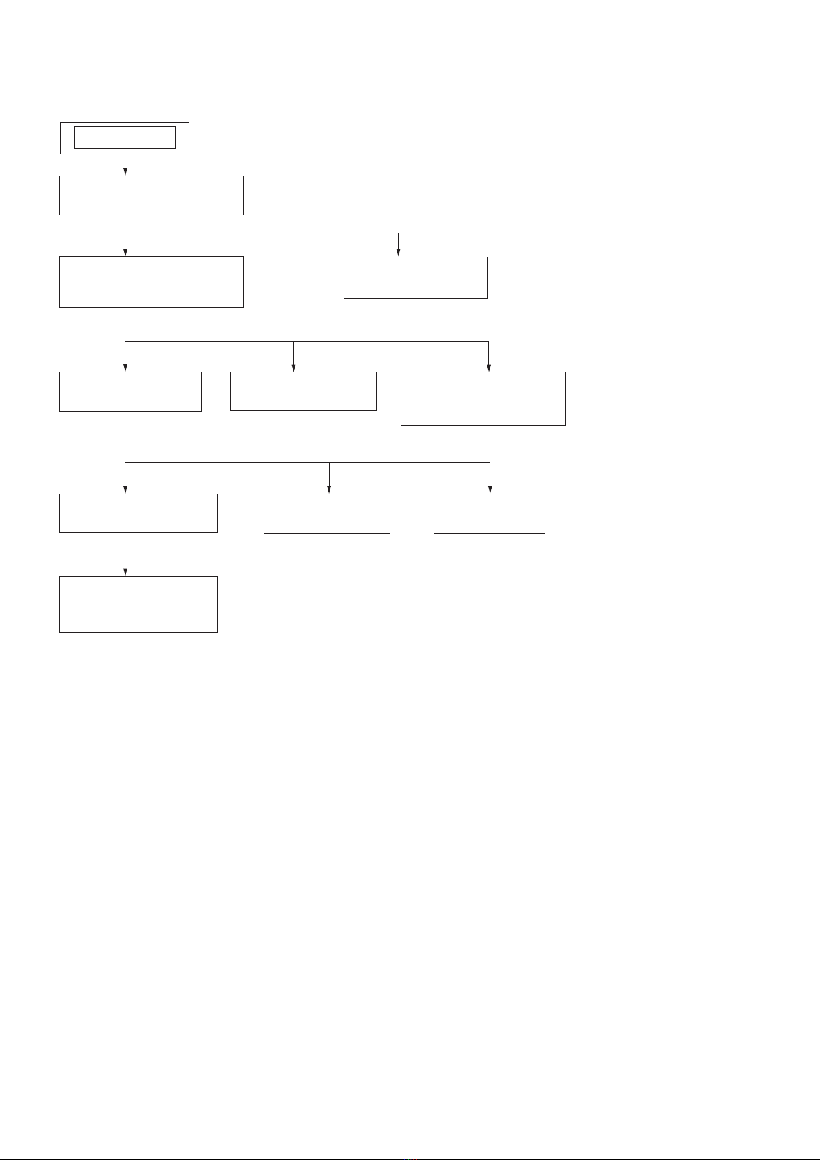
Example of folder structure and playing order
Folder
Notes on MP3/WMA discs
[
During this time, “READING” is displayed. If there are many folders
on a disc to be used for MP3/WMA listening.
[
[
[Maximum number of folders: 150
Maximum directory steps: 8
[
characters.
[
Other characters are displayed as “_”.
[
has the ID3 tag information, “song title”, “artist name”, and “album
name” can be displayed.
[
[
generate random noise that could damage your speakers.
[
[
may not be played as shown in the illustration.
Listening to the radio
1Press RADIO RE on the unit (BAND RK on the
remote) repeatedly.
Each time you press the button, the indication changes
as follows:
“FM” U“A M ”.
2Hold down TUNE + or – until the frequency digits
begin to change in the display.
If you cannot tune in a station, press TUNE + or –
repeatedlytochangethefrequencystepbystep.
When an FM stereo broadcast is received, “ST”
appears.
Tip
If the FM broadcast is noisy, press MODE until “MONO” appears
in the display and the radio will play in monaural.
Changing the AM tuning interval
If you need to change the AM tuning interval, do the
following:
1Press RADIO RE on the unit until“AM” is displayed.
2Press DISPLAY/ENTER on the unit for 2 seconds.
3Press RADIO RE on the unit for 2 seconds.
4Press PRESET + or – on the unit to select “9k
STEP” for 9 kHz interval or “10k STEP”for 10 kHz
interval.
5Press DISPLAY/ENTER on the unit.
your preset AM radio stations.
Opening/closing the Sliding Tray
Connecting a USB device
1Press RL.
RH is ejected.
2Connect your USB device to the (USB) port RH.
Tip
A digital music player is charged automatically in the USB mode when
connectedtothe (USB)portRH.
Closing the Sliding Tray
1Remove the USB device (see“Listening to music of a
USB device”).
2Slide the Lock RM as indicated by the arrow.
Lock RM
3Push the Sliding Tray RH into the unit until it clicks.
Notes
[Do not carry the unit with a USB device inserted to the connector.
Doing so may cause a malfunction.
[Be sure to store the Sliding Tray RH before moving the unit.
Basic Operations
Listening to music of a USB device
You can listen to music stored on an optional USB device
(digital music player or USB storage media).
this unit.
See “Playable USB devices” on the back page for a list of
USB devices that can be connected to this unit.
* Files with copyright protection (Digital Rights Management) cannot
be played on this unit.
1Press USB RE on the unit.
2Connect the USB device to the (USB) port RH (See
“Connecting a USB device”).
“USB MEMORY” appears in the display.
3Press V.
File number
playing time will appear
4Press VOLUME + or – (or VOL + or – on the remote)
RT to adjust the volume.
Other operations
To Press
Pause playback V.Toresumeplay,pressthe
button again*.
Stop playback Y.
Select a folder + or – .
or .
Find a point in a Hold down or during
playback, and release the button at
the desired point.
Select Repeat Play REPEAT on the unit repeatedly
until “ ”or“ 1” appears.
Remove the USB
device
Hold down Yuntil “NO DEV”
appears, then remove the USB
device.
*
Tips
[
playingtimetobeplayedaredisplayed.
[
Y.
Note
Always hold down Yandmakesurethat“NODEV”appears
before removing the USB device. Removing the USB device while
“NO DEV” is not displayed may corrupt the data on the USB device
or damage the USB device itself.
To change the play mode
Press MODE repeatedly while the USB device is not
device (or in the selected folder while “ ” lights up) one
SHUF”), or
Program Play (“PGM”).
Notes on the USB device
[You c a nn o t ch a ng e t he p l ay m o d e du r in g p la y b ac k .
[Some time may be needed before playback starts when:
– the folder structure is complex.
– the USB device is close to capacity.
[
[Do not connect a USB device to the unit through a USB hub.
[For some USB devices, when an operation is performed on the USB
device,theremaybeadelaybeforeitiscarriedoutonthisunit.
[
connected USB device.
[
on the connected USB device.
[
skipped.
[
[
or malfunction.
[
contained on a single USB device.
[
recording devices, and recording media cannot be guaranteed. If you
use an incompatible USB device, sound skipping or noise may be
produced,orthedevicemaynotplayatall.
Connecting optional components
You can enjoy the sound from an optional component
such as a portable digital music player through the
component before making any connections. For details,
refertotheinstructionmanualofthecomponenttobe
connected.
1Connect the AUDIO IN jack RB on the unit to the line
output jack of the portable digital music player or
other components using an audio connecting cable
(not supplied).
2Turn the unit and the connected component on.
3Press AUDIO IN RE and start playing sound on the
connected component.
from the speakers.
To connect the unit to a TV or VCR, use an extension
cable (not supplied) with a stereo-mini jack on one end
and two phono plugs on the other end.
Before using the unit
About the operating voltage
the unit. For changing the AM tuning interval, radio
frequency range, and AC operation, check the operating
voltage of your unit.
Press OPERATE .
To adjust the volume
Press VOLUME +, – (VOL +, – on the remote) RT.
To listen through headphones
Connect the headphones to the J(headphones) jack RG.
To reinforce the bass sound
Press MEGA BASS on the unit.
“MEGA BASS” appears in the display.
To return to normal sound, press the button again.
Playing a CD/MP3/WMA disc
1Press CD RE on the unit.
(On the remote, press OPERATE andthenpress
FUNCTION RI repeatedly until “CD” appears in the
display.)
2Press ;PUSH OPEN/CLOSE on the unit, and
place a disc with the label side up in the CD
compartment.
To close the CD compartment, press ;PUSH OPEN/
CLOSE on the unit.
3Press V.
When you place MP3/WMA discs, “MP3” or “WMA”
information.
Audio CD
Track number Playing time
MP3/WMA disc (Example: When you place MP3 disc)
File number
playing time will appear
To Press
Pause playback V. To resume play, press it
again.
Stop playback Y.
Go to the next
track/MP3/WMA
.
Go back to the
previous track/
.
Select a folder on
an MP3/WMA
disc
+ on the unit to go forward and
– to go backward .
Locate a point
while listening to
the sound
(forward) or (backward)
on the unit while playing and
Locate a point
while observing
the display
(forward) or (backward)
on the unit in pause and hold it
Remove the CD ;PUSH OPEN/CLOSE .
* VOLUME + (VOL + on the remote) RT and Von the unit have
a tactile dot.
SECTION 2
GENERAL This section is extracted
from instruction manual.

ZS-PS20CP
7
Using the display
You can check information about the CD using the
display.
Checking the information of an audio CD
To check the total track number and playing
time of the CD
Press Yto stop the CD playback.
Total track number
Total playing time
Checking the information of an MP3/WMA
disc
To check the total folder number on the CD
Press Yto stop the CD playback.
(Example: When you place MP3 disc)
Total folder number
Press DISPLAY/ENTER on the unit while playing an
#
S
)*
S
)
S
)*
*
appears in the display.
repeatedly (Repeat Play)
1Press CD RE on the unit.
“CD” appears in the display.
2Proceed as follows:
To repeat Do this
A single track/
MP3/WMA
1
Press REPEAT
on the unit until
“1” appears.
2Press
or
to select the
to repeat.
3Press
V
.
All tracks/
MP3/WMA
1 Press REPEAT
on the unit
until
“”appears.
2Press
V
.
Aselected
folder (MP3/
WMA disc
only)
1 Press MODE
until “ ”appears
andthenpressREPEAT
until
“REP” appears.
2 Select the folder by pressing + or
–
.
3Press
V
.
Tracks/MP3/
random order
1
2 Press REPEAT
on the unit
until
“”appears.
3Press
V
.
MP3/WMA
selected folder
in random
order (MP3/
WMA disc
only)
1
order”).
2 Press REPEAT
on the unit until
“”appears.
3Press
V
.
Programed
tracks/MP3/
1
“Creating your own program”).
2 Press REPEAT
on the unit
until
“”appears.
3Press
V
.
To cancel Repeat Play
Press REPEAT
on the unit until “ ” disappears from
the display.
Other Operations
random order
1Press CD RE on the unit.
“CD” appears in the display.
2Press MODE until“SHUF”appears in the display.
only), press MODE on the unit until “ ”and
+ or –
on the unit to select the folder you want.
3Press V
until “SHUF”
disappears from the display.
Tips
[
.
[
Creating your own program (Program
Play)
You can arrange the playing order of up to 25 tracks/
1Press CD RE on the unit.
“CD” appears in the display.
2Press MODE until“PGM”appears in the display.
3Press or to select the track/MP3/WMA
to add it to
the program.
Repeat to program other tracks in the order that you
want.
number is added.
Audio CD (Program Play)
Total playing time of the selected track
Programmed track number
MP3/WMA disc (Program Play) (Example:When you place MP3 disc)
4Press Vto start Program Play.
To cancel Program Play
until “PGM”
disappears from the display.
To clear the program you set
Press Y
.
“NO STEP” appears in the display for 2 seconds, and the
same display information as when inserting a CD
appears.
Tips
[You can play the same program again, since the program is saved,
until you press Yor open the CD compartment.
[
Presetting radio stations
You can store radio stations in unit’s memory. You can
preset up to 30 radio stations, 20 for FM and 10 for AM
in any order.
1Press RADIO RE repeatedly on the unit to select the
band.
2Hold down RADIO RE on the unit for 2 seconds until
3Press DISPLAY/ENTER on the unit.
frequencies to higher ones.
If a station cannot be preset automatically
You may need to preset a station with a weak signal
manually.
1Press RADIO RE repeatedly on the unit to select the
band.
2Tune in the station you want.
3Hold down DISPLAY/ENTER on the unit for 2
display.
4Press PRESET + or – on the unit until the preset
display.
5Press DISPLAY/ENTER on the unit.
Tip
AC power cord or remove the batteries.
Playing preset radio stations
1Press RADIO RE repeatedly on the unit to select the
band.
2Press PRESET + or – on the unit to tune in the
stored station.
Falling asleep to music
1Play the music source you want.
2Press SLEEP to display “SLEEP”.
3Press SLEEP to select the minutes until the unit
Each time you press the button, the indication changes
as follows:
“AUTO*” U“60MIN” U“30MIN” U“20MIN” U
“10MIN” U“OFF”.
* When you select “AUTO”, the CD and USB stops playing in 90
minutes.
automatically.
,the
currently displayed time option is entered.
To cancel the sleep function
Press OPERATE
repeatedly to set the sleep timer to “OFF” in step 3.
Playable USB devices
You can use the following Sony USB devices on this unit.
Other USB devices are not playable on this unit.
January 2008)
Product name Model name
Walk man 3NWD-B103 / B103F / B105 /
B105F
NWZ-A815/A816/A818
NWZ-S515/S516/S615F/S616F/
S618F/S716F
Check the websites below for the latest information about
compatible devices.
For customers in Europe:
<http://support.sony-europe.com/>
For customers in Latin America:
<http://www.sony-latin.com/pa/info>
ForcustomersinAsiaandOceania:
<http://www.sony-asia.com/section/support>
Notes
[Whenformattingtheabovemodels,besuretoformatusingthe
[Do not use any other than these USB devices. Operation of models
not listed here is not guaranteed.
[Operation may not always be ensured even when using these USB
devices.
[Some of these USB devices may not be available for purchase in
certain areas.
[
protection is not supported.
[Files downloaded from a music download website may not be
played.
[Connection through a hub is not supported.

ZS-PS20CP
8
SECTION 3
DISASSEMBLY
• This set can be disassembled in the order shown below.
3-1. CABINET (REAR) ASSY
(Page 9)
3-2. CABINET (FRONT) ASSY,
CABINET (UPPER) ASSY
(Page 9)
SET
3-3. MAIN BOARD
(Page 10)
3-8. USB TRAY ASSY
(Page 12)
3-4. CD BLOCK ASSY
(Page 10)
3-5. OPTICAL PICK-UP,
CD BOARD
(Page 11)
3-6. LCD BOARD
(Page 11)
3-7. CD LID
(Page 12)
3-10. POWER BOARD
(Page 13)
3-9. KEY (VOL) BOARD,
KEY (FUNC) BOARD
(Page 13)

ZS-PS20CP
9
Note: Follow the disassembly procedure in the numerical order given.
3-1. CABINET (REAR) ASSY
3-2. CABINET (FRONT) ASSY, CABINET (UPPER) ASSY
two screws
((+) BV tapping (B2.6))
screw
((+) BV tapping (B2.6))
screw
((+) BV tapping (B2.6))
cabinet (rear) assy
handle
telescopic antenna
three screws
((+) BV tapping (B2.6))
battery case lid
CN906 (3P)
CN1 (2P)
screw
((+) BV tapping (B2.6))
cabinet (upper) assy
cabinet (front) assy
screw
((+) BV tapping (B2.6))
CN403 (2P)
CN1003 (4P)
CN1005 (2P)

ZS-PS20CP
10
3-3. MAIN BOARD
3-4. CD BLOCK ASSY
two screws
((+) BV tapping (B2.6))
two screws
((+) BV tapping (B2.6))
CN805 (2P)
CN307 (4P)
CN301 (3P)
connector
(S801)
cabinet (upper) section
RT MAIN board
holder (jack)
AUDIO IN board
HEADPHONE board
wire (flat type)(20 core)
(CN803)
RB wire (flat type)(20 core)
(CN804)
two screws
((+) BV tapping (B2.6))
two screws
((+) BV tapping (B2.6))
CD chassis
CD block assy
cabinet (upper) section
CN703 (6P)

ZS-PS20CP
11
3-5. OPTICAL PICK-UP, CD BOARD
3-6. LCD BOARD
wire (flat type) (16 core)
(CN701) CD board
CD cover
optical pick-up
two vibration rubbers
(GREEN)
two vibration rubbers
(RED)
screw
(+BVTT 2 ×6)
Remove the four solders.
four screws
((+) BV tapping (B2.6))
three screws
((+) BV tapping (B2.6))
LCD board
cabinet (upper) section

ZS-PS20CP
12
3-8. USB TRAY ASSY
3-7. CD LID
screw
((+) BV tapping (B2.6))
cabinet (upper) section
damper
CD lid
CD spring
two screws
((+) BV tapping (B2.6))
two screws
((+) BV tapping (B2.6))
CN1006 (2P)
wire (flat type)(6 core)
(CN1004)
USB tray assy
cabinet (front) assy

ZS-PS20CP
13
3-9. KEY (VOL) BOARD, KEY (FUNC) BOARD
3-10. POWER BOARD
three screws
((+) BV tapping (B2.6))
two screws
((+) BV tapping (B2.6))
screw
((+) BV tapping (B2.6))
screw
((+) BV tapping (B2.6))
two hold boards
two hold boards
button (VOL)
button (function)
KEY (VOL) board
RB KEY (FUNC) board
CN401 (2P)
cabinet (front) assy
two screws
((+) BV tapping (B2.6))
screw
((+) BV tapping (B2.6))
POWER board
two screws
((+) BV tapping (B2.6))
ferrite core
CN903 (2P)
cabinet (rear) section

ZS-PS20CP
14
SECTION 4
ELECTRICAL ADJUSTMENTS
TUNER SECTION 0 dB = 1 μV
• AM Section
Setting:
RADIO BAND•AUTO PRESET button: AM
Put the lead-wire
antenna close to
the set.
AM RF signal
generator
30% amplitude
modulation by
400 Hz signal
• FM Section
Setting:
RADIO BAND•AUTO PRESET button: FM
ANT2
FM RF signal
generator
75 kHz frequency
deviation by 1 kHz signal
output level : as low as possible
0.01 μF
set
• Connecting Level Meter (FM, AM)
Jjack (J321)
set
32 Ω
level meter
(range: 0.5–5 V ac)
• Connecting Digital Voltmeter (FM, AM)
digital
voltmeter
100 kΩ
TP (VT)
• Repeat the procedures in each adjustment several times, and the
frequency coverage and tracking adjustments should be finally
done by the trimmer capacitors.
AM IF ADJUSTMENT
Adjust for a maximum reading on level meter.
T1
450 kHz
AM FREQUENCY COVERAGE ADJUSTMENT
Frequency Display 530 kHz 1,610 kHz
Reading on Digital voltmeter 0.8 ± 0.1 V 5.0 ± 0.6 V
Adjustment Part L3 <confirmation>
AM TRACKING ADJUSTMENT
Adjust for a maximum reading on level meter.
ANT1 CT3
620 kHz 1,400 kHz
FM IF ADJUSTMENT
Adjust for a maximum reading on level meter.
L6
10.7 MHz
FM FREQUENCY COVERAGE ADJUSTMENT
Frequency Display 87.5 MHz 108 MHz
Reading on Digital voltmeter 1.5 ± 0.5 V 3.0 ± 0.3 V
Adjustment Part <confirmation> L2
FM TRACKING ADJUSTMENT
Adjust for a maximum reading on level meter.
L1 CT1
87.5 MHz 108 MHz
Adjustment Location: See page 15.

ZS-PS20CP
15
Adjustment Location:
Test Point:
L3: AM FREQUENCY COVERAGE
ADJUSTMENT
L2: FM FREQUENCY COVERAGE
ADJUSTMENT
CT1: FM TRACKING
ADJUSTMENT ANT1: AM TRACKING
ADJUSTMENT
CT3: AM TRACKING ADJUSTMENT
L1: FM TRACKING ADJUSTMENT
T1: AM IF ADJUSTMENT
– MAIN BOARD (Component Side) –
L6: FM IF ADJUSTMENT
118
36 19
IC1
C14
C13 C15
C3
C6
C7
C5
C67
C12
C11
C10
C1
C2
C4
C21
C70
C22
C23
C26
CF3
CF2
C27
C33
R28
R25
R10
R16
R8
R270 R22
R18
C37
C36
R42
JW187
JW183
JW204
JW217
JW212
JW211
R20
D6
R26
C16
C45
C9
R6
R1
R3
R12
R15
C42
C41
X1 C40
C34
C35
C38
J
W
J
JW185
JW184
JW205
CT3
CT1
D3
L3
D2 L2
D1
L1
D4
D5
JW215
JW203
JW210
JW209
JW216
JW213
JW214
C31
C32
C25
C72
R41
R19
R21
R27
C20
C46
C43
C17
C24
R17
R170
R23
R29
C28
L6
T1
R9
R4
R13
R7
R39
R14
R24
R11
R2
R5
C29
C19
C30
C326
C18
C39
L10
MAIN BOARD
TP (VT) TP (GND)

ZS-PS20CP
16
CD section adjustments are done automatically in this set.
In case of operation check, confirm that focus bias.
FOCUS BIAS CHECK
1. Connect the oscilloscope between IC701 pin 2and pin qa (or
TP (RF OUT) and TP (VC)).
2. Insert the disc (PATD-012 (Tr 15)). (Part No. : 4-225-203-01)
3. Press the [N X] (CD) button.
4. Confirm that the oscilloscope waveform is as shown in the fig-
ure below. (eye pattern)
A good eye pattern means that the diamond shape (◊) in the
center of the waveform can be clearly distinguished.
• RF signal reference waveform (eye pattern)
RF level :
1.1 ± 0.4 Vp-p
VOLT/DIV : 50 mV (10 : 1 probe in use)
TIME/DIV : 500 nS
When observing the eye pattern, set the oscilloscope for AC range
and raise vertical sensitivity.
CD SECTION
Test Point:
40
LIMIT
21
20
1
8061
60
41
1
3
116
AVCC
SPD
SLD
TRK
FCS
TE
VC
FE
RF OUT
AVGND
E
(11)
11
1-877-003-
IC701
IC70
4
C725
R728
R722
R721
R719
R718
R716
C704
C702
R754
R753
R752
R751
R749
R745
FB702
X701
R717
C711
C726
R534
C714
C715
Q701
C712
C529
C724
R735
R736
R733
R727
R734 C722
R731 C721
C716
C710
C708
R702 R701
C759
C701
C754
R755
R748 R747
R746
C709
R724
R732
C719
C728
C729
R744
R742
R741
R740
R737
C764
CN701
R533R723
R51
R710
R709
R707
R706
C703
TP (RF OUT)
– CD BOARD (Conductor Side) –
TP (VC)

ZS-PS20CP
ZS-PS20CP
1717
A IN
RF OUT
A
C
B
D
E
F
A
C
B
D
E
F
5
2 1
C IN
6
B IN
7
D IN
8
E IN
RF SIGNAL PROCESSOR EFMIN
RF OUT
13
F IN
14
LDLD
MD
VR
VC
TD+
TD–
SL+
SL–
FD+
+
FD–
–
PD
LDO
APC
18
LDS
19
VREF
VREF
TU-VDD
VDD
D951
D DO
D DI
D CL
D CE
D RESB
USB-TXD
USB-RXD
SLEEP
+6V
+3.3V
VC VBUS
5V
AC IN
VBUS
5V
L901
IC901 F901
BATT
F902
D901—904
RECT
T901
POWER
TRANSFORMER
DRY BATTERY
SIZE "D"
(IEC DESIGNATION R20)
6PCS, 9V
D906
+3.3V
(CD)
MUTE
VC
VC
11
LD POWER
CONTROLLER
Q701
TRACKING
COIL
DRIVE
SERVO
CONTROL
8FS
DIGITAL
FILTER
&
1-bit DAC
SYNCHRONIZATION
DETECTION
EFM DEMODULATION
OPTICAL PICK-UP
BLOCK
(KSS-213C)
SLED/SPINDLE
MOTOR DRIVER,
TRACKING/FOCUS
COIL DRIVER
IC703
SYSTEM SERVO PROCESSOR,
DIGITAL SIGNAL PROCESSOR
IC701
SYSTEM CONTROLLER
IC801 (1/2)
TRACKING
COIL
FOCUS
COIL
M702
(SLED)
24 25
23
19
20
FOCUS
COIL
DRIVE
SLED
MOTOR
DRIVE
5
6
10
9
SPINDLE
MOTOR
DRIVE
MM
SP+
I-CD LID
SP–
+
–
M701
(SPINDLE)
S701
(LIMIT)
MM
18
4
11
2
27
TDO
23
FDO
22
SLDO
24
SPDO
25
CONT3
32
D RESB
47
D CE
43
D CL
44
D DI
45
D DO
46
93 94 5 3 4
M-MUTE
O-CD RES
O-CD CE
O-CD CLK
O-CD DO
I-CD DI
92
USB-RXD
100
O-USB SLEEP
91
USB-TXD
5
CONT
99
O-SW EN
98
I-SW FLG
2
45
S801
PUSH
OPEN/
CLOSE
;
I-REG 6.0V
23
O-POWER
36
I-RES
11
I-REG 3.3V
22
O-5V-ON
38
1
2
I-REG 9.0V
24
+6V
REG
Q955,D953
RIPPLE
FILTER
Q905
RESET
IC803
B+ SWITCH
Q804,805
POWER
PROTECT
SWITCH
Q952,953
POWER
PROTECT
SWITCH
Q951
+9V
(SW)
+3.3V REG
IC804
VBUS +5V
CONTROL
IC704
XOUT
XIN
73 72
X701
16.9344MHz
CLOCK
GENERATOR
MCU I/F
LCHO 76
RCHO 78
STREQ 54
UHD+ D+
38
UHD– D–
37
STCK 55
STDATA 56
PCMREQ 65
PCMLRSY 62
PCMBCK 63
PCMDATA 64
P70/INT0/TOLCP/AN8
46
P24/INT5/INT7/SCK4
33
P22/INT4/SO4/RD
31
P23/INT4/SI4/WR
32
P07/AN7/T70
28
P06/AN6/T60
27
P05/AN5/CK0/SDAT
LCH
RCH
26
RES
2
P16/T1PWML/DE
15
P12/SCK
11
P71/INT1/TOHCP/AN9
47
P30/UTX1
45
P31/URX1
44
P10/SO
9
P11/SI
10
FB
4
VOUT
2VIN 1
7
6
X702
12MHz
USB I/F
IC702
(USB TRAY UNIT)
CF2
CF1
AMAIN
SECTION
BMAIN
SECTION
J901
AC IN
•SIGNAL PATH
: USB
: CD
SECTION 5
DIAGRAMS
5-1. BLOCK DIAGRAM – CD Section –
(Page 18)
(Page 18)

ZS-PS20CP
ZS-PS20CP
1818
5-2. BLOCK DIAGRAM – MAIN Section –
TU-VDD
25
SCL
SDA
OUT1 L
POWER AMP
IC303 R-CH
SP101
SPEAKER
(L-CH)
SP201
SPEAKER
(R-CH)
J321
IN L3
IN R3
IN L1
IN R1
IN L2
IN R2
R-CH
R-CH
R-CH
R-CH
R-CH
REMOTE CONTROL
RECEIVER
O-VOL CLK
O-VOL DATA
83–86
LIQUID CRYSTAL
DISPLAY PANEL
LCD401
SYSTEM CONTROLLER
IC801 (2/2)
8 6
O-COM1
|
O-COM4
O-SEG 1
|
O-SEG 29
EEPROM
IC802
EEPROM-SCL
EEPROM-SDA
28
I-WAKE UP
Q803, D801, 802
D803
IC401
I-KEY1
25
I-KEY2
26
I-KEY3
27
6 223
OUT2 R 18
6
5
J
O-A MUTE
35
MUTE
Q124
9V (SW)
KEY3
+9V (SW)
AC IN
KEY1
KEY2
26
LCH
RCH
65
910 29 88
TU_IN_R
+9V
(SW)
KEY NETWORK
D401
OPR/BATT
O-TU-DATA
O-TU COUNT
O-TU-CLK
O-TU CE
I-RMC
I-CA CHECK
15
CF1
16
CF2
18
O-CLOCK
SHIFT1
19
O-CLOCK
SHIFT2
X801
10MHz
12
XT1
13
XT2
X802
32.768kHz
DI
X IN
X OUT
CL
LP-OUT
AM
OSC
AM
MIX
FM
MIX
FM
OSC
AM RF-IN
AM OSC
REG
FM
RF-IN
FM
IF-IN
AM
IF-IN
X1
75kHz
20 19 16 17
CE
15
DO
18
41 40 4244
23 22 13
12
28
LP-IN
27
PD
26
1
31
2
5 7
8
11
36
3234
T1
L6
CF3
L2
L1 CT1
TU-VDDTU-VDD
D1 D2
CT3
D3
CT3,ANT1
AM
TRACKING
L3
AM
FREQUENCY
COVERAGE
L2
FM
FREQUENCY
COVERAGE
L6
FM
IF
T1
AM
IF
ANT2
FM
TELESCOPIC
ANTENNA
AM
DET
FM
DET
AF
BUFFER
FM
MPX
R-OUT
L-OUT
TU-VDD
FM-DET
FM/AM RF AMP, MIX, OSC, IF AMP,DET,
FM MPX
IC1
L3
+9V
(SW)
D324
(VT)
CF2
TU-VDD
TU-VDD
ANT1
AM
FERRITE-ROD
ANTENNA
AM
MIX-OUT
FM
MIX-OUT
FM
RF-OUT FM OSC
DET-OUT MPX-IN
3
S413–417
S406–412
S401–405
BCD
SECTION
R-CH
2
1
4
3
INPUT SELECT
ELECTRONIC VOLUME
IC302
J322
AUDIO IN
A
CD
SECTION
79–56,
53–49
CLOCK
SHIFT
SWITCH
Q801,802
•R-ch is omitted due to same as L-ch.
CT1,L1
FM
TRACKING
•SIGNAL PATH
: AM
: FM
: AUDIO IN
: CD
: USB
(Page 17)
(Page 17)

ZS-PS20CP
ZS-PS20CP
1919
• Waveforms
– CD Board –
For Schematic Diagrams.
Note:
• All capacitors are in μF unless otherwise noted. (p: pF) 50
WV or less are not indicated except for electrolytics and
tantalums.
• All resistors are in Ωand 1/4 W or less unless otherwise
specified.
• f: internal component.
• C: panel designation.
THIS NOTE IS COMMON FOR PRINTED WIRING BOARDS AND SCHEMATIC DIAGRAMS.
(In addition to this, the necessary note is printed in each block.)
• A: B+ Line.
• H: adjustment for repair.
• Voltages and waveforms are dc with respect to ground
under no-signal conditions.
[ ] : USB
– MAIN (1/3) Board –
no mark
: FM
( ): AM
– CD Board –
no mark
: CD PLAY
[ ] : USB
– MAIN (2/3), (3/3) and Other Boards –
no mark
: FM
( ): AM
< >: CD PLAY
[ ] : USB
• Voltages are taken with VOM (Input impedance 10 MΩ).
Voltage variations may be noted due to normal production
tolerances.
• Waveforms are taken with a oscilloscope.
Voltage variations may be noted due to normal production
tolerances.
• Circled numbers refer to waveforms.
• Signal path.
F: FM
f: AM
L: AUDIO IN
J: CD PLAY
c: USB
• Abbreviation
AUS : Australian model
KR : Korea model
For Printed Wiring Boards.
Note:
• X: Parts extracted from the component side.
• Y: Parts extracted from the conductor side.
• W: indicates side identified with part number.
• f: internal component.
• : Pattern from the side which enables seeing.
(The other layers' patterns are not indicated.)
• Indication of transistor.
C
B
These are omitted.
E
E
B
These are omitted.
CE
• Abbreviation
AUS : Australian model
KR : Korea model
Caution:
Pattern face side:
(Conductor Side)
Parts face side:
(Component Side)
Parts on the pattern face side seen from
the pattern face are indicated.
Parts on the parts face side seen from
the parts face are indicated.
Note: The components identified by mark 0or dotted
line with mark 0are critical for safety.
Replace only with part number specified.
• Circuit Boards Location
HEADPHONE board
LCD board
USB RELAY (1) board
KEY (FUNC) board
KEY (VOL) board
MAIN board
BATTERY (1) board
BATTERY (2) board
AUDIO IN board
CD board
POWER board
1 V/DIV, 10 μsec/DIV
IC1 X (X OUT)
1 V/DIV, 20 μsec/DIV
IC801 RE (XT2)
1 V/DIV, 0.05 μsec/DIV
IC801 RI (CF2)
75 kHz
32.768 kHz
3.6 Vp-p
9.98 MHz (FM)
10.0 MHz (AM, CD, USB)
2.8 Vp-p
2.2 Vp-p
IC701 (RF MON (FE))
IC701 RI (TE)
100 mV/DIV, 2 msec/DIV
500 mV/DIV, 0.5 μsec/DIV
100 mV/DIV, 2 msec/DIV
IC701 VT (XOUT)
1 V/DIV, 0.05 μsec/DIV
IC702 (CF1) (USB PLAY)
1 V/DIV, 50 μsec/DIV
IC701 (RF OUT)
Approx. 100 mVp-p
16.9344 MHz
1.6 V
1.1 ± 0.4 Vp-p 2.3 Vp-p
Approx. 100 mVp-p
1.6 V
12 MHz
2.5 Vp-p
– MAIN Board –

ZS-PS20CP
ZS-PS20CP
2020
5-3. PRINTED WIRING BOARD – CD Section (1/2) – • : Uses unleaded solder.• See page 19 for Circuit Boards Location.
1234567891011121314
A
B
C
D
E
F
G
H
I
J
CD BOARD (SIDE A)
(11)
11
1-877-003-
C524
C765
R761
R508
C740
R715
R759
C528
C527
R713
R704
R712
R757
R760
C749
R703
R705
C755 C747 C742
C743
C744
C745
C746
C756
C758
C706
C713 C748
C735
C737
C739C736C738
FB701
C757
C717
C723
R726
R743
R507
C505
C503
R501
R506 R505
R502R503R504
R510 R509
R764
C501
C798
C799
C797
C776 C778
C766
C794
C718
C727
C741
C784
C783
C782
C777
R750
R738
C730
C731
C732
C733
C734
R767
R769
R770
C779
C791
C790
R790
R786
R789
R785
C792
C523
C707
Other manuals for ZS-PS20CP
1
Table of contents
Other Sony Stereo System manuals

Sony
Sony HCD-EX770 User manual

Sony
Sony GTK-N1BT User manual

Sony
Sony LBT-D117CD User manual

Sony
Sony CPF-IX001 - Wireless PC-Linked Audio System Use and care manual

Sony
Sony HCD-CP300 User manual

Sony
Sony MHC-EC68PI User manual

Sony
Sony MHC-EC68PI User manual

Sony
Sony CMTBX1 - CMT BX1 Micro System User manual

Sony
Sony CMT-FX250 User manual

Sony
Sony HTC-WX5 User manual

Sony
Sony MHC-RG590S User manual

Sony
Sony HCD-GP5 User manual

Sony
Sony HCD-RG490; HCD-RG590 User manual

Sony
Sony CMT-EX100 User manual

Sony
Sony MEX-M70BT User manual

Sony
Sony ZS-PS50 User manual

Sony
Sony MHC-V82D User manual

Sony
Sony WX-GT90BT User manual

Sony
Sony CMT-ED1/ED1A User manual

Sony
Sony ZS-D55 User manual