Cardio Theater xTV-9T Product manual

®
xTV-9T
Cardio Theater xTV-9T Transmitter
Installation and Maintenance Guide


Installation and Maintenance Guide: Important Safety Guidelines 1
IMPORTANT SAFETY INSTRUCTIONS
Important Safety Guidelines
Always follow basic safety precautions when using this
equipment to reduce the chance of injury, fire, or damage.
• Read all precautions in this guide before installing and using
the equipment. Follow any labels on the equipment.
• Use the power adapter provided with the equipment. Plug the
power adapter into an appropriate, grounded power outlet as
marked on the equipment.
• Route power cords so that they are not walked on or pinched
by items placed upon or against them.
• Ensure that the equipment has adequate ventilation. Do not
place anything on top of or over the equipment. Do not use on
a cushioned surface that could block the ventilation openings.
• Keep the equipment away from water and moisture.
• Locate the equipment away from sources of heat, such as
radiators, heat registers, and stoves. Avoid temperature
extremes.
• Avoid dropping anything on or spilling anything inside the
equipment, because doing so can damage the electronics.
Regulatory Information
FCC Compliance Statement
This device complies with Part 15 of the FCC Rules. Operation is
subject to the following two conditions: (1) this device may not
cause harmful interference, and (2) this device must accept any
interference received, including interference that may cause
undesired operation.
The Cardio Theater xTV-9T Transmitter has been tested and
found to comply with the limits pursuant to Part 15 C of CFR 47,
FCC Rules. These limits are designed to provide reasonable
protection against harmful interference in a residential installation.
The xTV-9T Transmitter generates, uses, and can radiate radio
frequency energy and, if not installed and used in accordance
with the owner’s manual instructions, may cause harmful
interference to radio communications.
Per FCC rules, changes or modifications not
expressly approved by the manufacturer
could void the user’s authority to operate
the equipment.
WARNIN
G

Installation and Maintenance Guide: Table of Contents 2
Table of Contents
Important Safety Guidelines .................................................1
Regulatory Information .................................................................. 1
Before You Begin .....................................................................3
Obtaining Service ........................................................................... 3
Preparations ..............................................................................4
Unpacking the Equipment ............................................................ 4
Installation Requirements .............................................................. 4
Installing the Transmitter ...................................................... 6
Maintaining and Troubleshooting ..................................... 10
Cleaning the Transmitter .............................................................10
Troubleshooting the Transmitter ...............................................10
Limited Warranty .................................................................... 13

Installation and Maintenance Guide: Before You Begin 3
Before You Begin
With the Cardio Theater®xTV wireless system, fitness facilities can
add entertainment to exercise rooms without the high cabling costs
usually associated with entertainment systems. The xTV wireless
system gives people the choice of listening to music, radio, or
programs shown on TVs while they exercise. The person simply
plugs a stereo headphone into a receiver, selects the desired
entertainment, and exercises while listening to high-fidelity sound.
An xTV wireless system consists of one or more xTV-9T Transmitters,
one for each TV and audio component, and a number of xTV-9R
Receivers installed on exercise equipment throughout the room.
Because the xTV-9T Transmitter supports 32 different frequencies,
facilities can install up to 32 transmitters to support a wide variety of
entertainment options.
This guide explains how to install and maintain an xTV-9T
Transmitter. For proper installation, please read this guide thoroughly
and follow the instructions.
Note: For information about the xTV-9R Receivers, refer to the
xTV-9R Receiver Installation and Maintenance Guide.
Important: If you have Cardio Theater LCS or Broadcast Vision
installed at the facility, contact Cardio Theater Technical Support.
The xTV-9T Transmitter uses the same frequencies as these
products; it is important to avoid frequencies that are already being
used to assure good audio quality and proper operation.
Obtaining Service
Do not attempt to service the xTV-9T Transmitter except as described
in this guide. For information about product operation or service, refer
to the Cardio Theater web site at www.cardiotheater.com or contact
an authorized dealer. For information about product operation or
service, contact an authorized Cardio Theater Technical Support
Representative at 1-800-776-6695 or service@cardiotheater.com.
Representatives are available to serve you from 6:00 am to 5:00 pm,
Monday through Friday, U.S.A. Pacific Time.
Returning Equipment to Cardio Theater
To return equipment to Cardio Theater for any reason, you must
contact Cardio Theater Technical Support and obtain a Return
Authorization Number (RMA). When requesting the RMA number,
explain why you are returning the equipment, for example you
ordered too many receivers and the extra receiver can be returned to
stock, or the equipment needs repairs.
Important: Equipment must be shipped with an RMA number in
order for Cardio Theater to process it. Any equipment received
without an RMA number will be returned to the sender.

Installation and Maintenance Guide: Preparations 4
Preparations
Remember to read and follow the instructions in this guide. If you do
not install the xTV-9T Transmitter according to these instructions,
you could void the Limited Warranty.
Unpacking the Equipment
The transmitter is shipped with the following items:
• One or more xTV-9T Transmitters as ordered
• Plastic screw driver used to set channel number,
1 per transmitter
• AC adapter for your country, 1 per transmitter
• RCA audio cable, 1 per transmitter
• Numbered signs to post near TVs and audio components
• These installation instructions
If any items are missing, contact the dealer from whom you
purchased the equipment or contact Cardio Theater Technical
Support.
Installation Requirements
Review the following installation requirements before assembly:
• You can install up to thirty-two transmitters, depending on the
infrastructure and radio frequency activity in the area.
• To ensure the best range and audio quality possible for the
transmitter(s), select a location for installing them without any
major internal obstructions, such as metal support posts, between
transmitters and receivers installed on the exercise equipment.
Transmitters and receivers should also be installed so they are
within 150 feet (46 meters) of each other and are in direct line of
sight.
• Cardio Theater recommends that you group audio components
together to minimize cabling. Also, install the transmitters and
other audio components in a central location for better
transmission coverage.
• If you are installing more than one transmitter, you must place
them at least 12 inches (31 cm) apart. Do not stack transmitters
on top of each other. If transmitters are placed too closely
together, the facility may experience poor sound quality.
• If the audio components are stacked in a cabinet, make sure the
equipment has adequate ventilation to avoid overheating.
xTV-9T

Installation and Maintenance Guide: Preparations 5
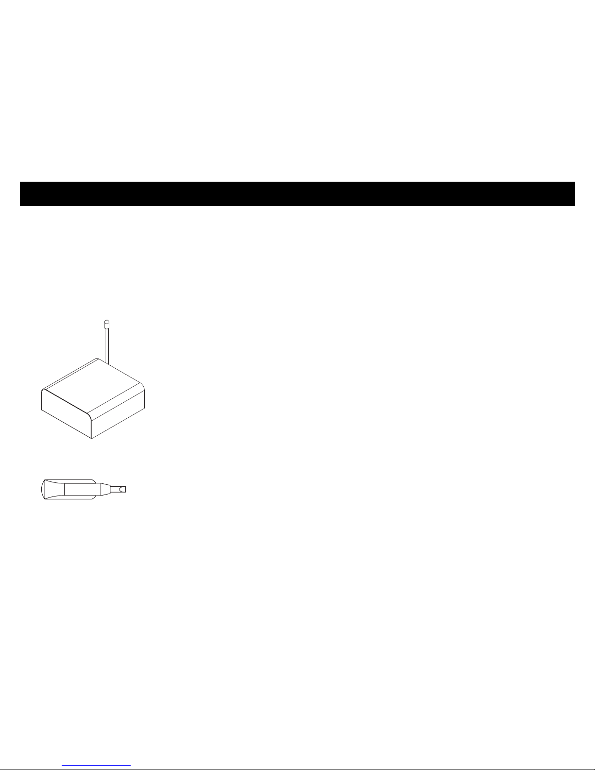
• Place the antenna on the transmitter so it is vertical. In addition,
the antenna should not touch or come near other transmitting
antennas or metal objects. Be sure to route cabling and power
cables away from the antenna, so they do not cause interference.
• Each transmitter requires a unique channel number. Channel
numbers on transmitters determine their frequencies. There is no
correlation between channel numbers on transmitters and channel
numbers shown on receivers when they are programmed.
• If you discover that some of the 900 MHz frequencies (see
Table 1) are used by outside non-controllable sources, you can set
the transmitter to avoid those frequencies. However, this will
reduce the number of channels available for you to use when
installing transmitters. If the outside non-controllable source
generates a powerful signal, it may also cause static interference
with the wireless system, reducing audio quality.
• With new xTV wireless installations, we recommend installing the
receivers on the equipment first, then installing the transmitters.
Doing so will allow installers to check the sound quality of the
transmitters throughout the room.
• The receiver automatically acquires the available channels from the
installed transmitters and assigns them to channel numbers,
starting with the lowest transmitting channel to the highest
transmitting channel, regardless of which channels are used. To
avoid confusion with people using the wireless system, you want
receivers to logically select TV and audio components based on
their placement. So, on the receiver, channel 1 would select the
first TV, channel 2 would select the second TV, and so on. To
support this logical usage, transmitters need to be installed in
channel order.
• Transmitters use Automatic Level Control (ALC) circuitry to
provide consistent sound levels to people using the receivers.
With this feature, once the sound level on TVs and other audio
components have been adjusted, the wireless system should not
experience sound fluctuations, which have been inherent in other
types of entertainment systems. To support this feature, the sound
level from the connected TV and audio components must be set to
a reasonable, median level. If the incoming sound level is set too
low, people may hear an excessive amount of background noise
while using the receivers. If the incoming sound level is set too
high, it may sound distorted through the receivers.

Installation and Maintenance Guide: Installing the Transmitter 6
Installing the Transmitter
1. Determine where you will install each transmitter. If possible,
locate the transmitters where their signals will have no
obstructions (such as metal support posts) to the receivers
installed on the exercise equipment. In addition, the distance
between receivers and transmitters should not exceed 150 feet
(46 meters).
2. Determine the channel number you want to assign to each
transmitter. Each transmitter requires a unique channel number.
Transmitters should be installed in order of their channel number
to make the wireless system easier to use. See Table 1.
Note: Table 1 provides blank columns that installing technicians
can use to note setup information. Consider providing a brief
description of what entertainment each transmitter provides (or
is connected to) and indicate the associated receiver channel
that gets assigned.
Table 1: Site with up to 32 transmitters
Transmitter
Channel
Transmitter
Frequency
Description of Channel
(Write a brief description
for your site)
Receiver
Channel
1905.0
2906.2
3 923.6
4 924.4
5 925.6
6 910.6
7 911.8
8 913.4
9 914.2
10 915.4
11 917.0
12 917.8
13 919.0
14 920.6
15 921.4
16 922.6
17 905.6
18 906.6
19 907.6
20 908.8
21 910.0
22 911.2
23 912.4
24 913.8
25 915.0
26 916.2
27 917.4
28 918.4
29 919.6
30 921.0
31 921.8
32 923.0

Installation and Maintenance Guide: Installing the Transmitter 7
3. Set the channel number on the transmitter by adjusting the two
Channel Select dials on the back with the supplied plastic screw
driver.
Figure 1 shows how to adjust a dial with the provided tool. Refer
to Tables 2 and 3 to determine how to adjust each dial to select a
channel number, based on your country.
Important: You must set the transmitter to an appropriate
channel number for your country. If it is set improperly, you may
be liable for fines or other punishments by local authorities.
Consult Cardio Theater Technical Support if your country is not
covered in the tables.
Figure 1: Set a unique channel number for each transmitter
Different channel numbers will provide better reception based on
whether or not other equipment in the facility are using the same
frequency, or possible influences from the facility infrastructure.
During installation, you may need to change the channel number
based on the quality of the sound captured by the receivers.
Table 2: Allowed channel numbers for U.S. and Canada
r
et
t
ims
n
ar
T
zH
M
00
9
CD
V9 re
wo
P
R
L
N
I
oi
d
uA l
e
n
n
a
h
C
t
c
e
l
eS lev
eL
m
o
c
.
r
e
t
a
e
ht
oi
dr
a
c
.
w
w
w
.seluRCCFehtfo51traPhtiwseilpmocecivedsihT
:snoitidnocowtgniwollofehtottcejbussinoitarepO
dna,ecnerefretnilufmrahesuactonyamecivedsihT)1(
,deviecerecnerefretnilufmrahynatpecca
tsumecivedsihT)2(
.noitarepoderisednuesuacyamtahtecnerefretnignidulcni
1
3
5
4
6
8
9
7
0
2
0
9
1
3
6
5
7
4
8
2
xTV-9T
ret
timsna
R
L
N
I
oi
d
uA le
n
na
hC
t
c
eleS leveL
m
o
c
.
r
e
t
a
eht
oi
dr
a
c
.
w
w
w
risednuesuacyamtfretnignidulcni
1
3
5
4
6
8
9
7
0
2
0
9
1
3
6
5
7
4
8
2
Channel
Number
Set Left
Dial
Set Right
Dial
101
202
303
404
505
606
707
808
909
10 1 0
11 1 1
12 1 2
13 1 3
14 1 4
15 1 5
16 1 6
17 1 7
18 1 8
19 1 9
20 2 0
21 2 1
22 2 2
23 2 3
24 2 4
25 2 5
26 2 6
27 2 7
28 2 8
29 2 9
30 3 0
31 3 1
32 3 2

Installation and Maintenance Guide: Installing the Transmitter 8
Table 3: Allowed channel numbers for Australia
4. Place the transmitter where it will operate. Make sure that it is
located in a well-ventilated area with both the front and back
easily accessible.
You can place the transmitter on top of the TV or audio
component it will be transmitting, or in a rack nearby.
Important: If you are installing more than one transmitter, you
must place them at least 12 inches (31 cm) apart. Do not stack
transmitters on top of each other. If transmitters are placed too
closely together, they may interfere with each other’s signals.
5. Adjust the antenna on the transmitter so that it is vertical.
6. Plug the power cord on the AC adapter, packaged with the
transmitter, into the back.
Important: Make sure the power cord is not near the antenna,
or it could interfere with the audio signal.
7. Plug the AC adapter into a nearby power outlet.
8. Connect one end of the RCA audio cable to the TV or audio
source. Observe and follow the color code of the RCA audio
cable connectors. If available, connect the RCA cable to the Line
Audio Output connector on the TV or audio source.
The Line Audio Output connector is recommended because it
always provides a consistent sound level and cannot be modified
by users.
9. Connect the other end of the RCA audio cable to the transmitter.
Observe and follow the color code of the RCA audio cable
connectors.
Important: Make sure the RCA cable is not near the power
cable, or it could interfere with the audio signal.
10.If connecting to a TV, turn off its speakers using the appropriate
menu function.
Channel
Number
Set Left
Dial
Set Right
Dial
103
204
305
411
512
613
714
815
916
10 2 6
11 2 7
12 2 8
13 2 9
14 3 0
15 3 1
16 3 2

Installation and Maintenance Guide: Installing the Transmitter 9
11.If you connected the RCA audio cable to a fixed audio output
connector, continue to step 12. Otherwise, set the sound level
so users receive a consistent sound level. You will need to look at
the back of the transmitter to perform this step. See Figure 2.
Figure 2: Watch the Level lights to adjust volume appropriately
a. Lower the sound on the TV or audio component so it has little
or no sound.
b. Begin increasing the sound on the TV or audio component
until the green Level light is solid and the red Level light is
barely flashing.
You have gone too far if the red Level light is flashing
frequently or glowing solidly. In this case, reduce the volume
until the red Level light flashes intermittently.
c. Stop adjusting the volume and watch the Level lights. The
transmitter will automatically correct its volume to level it out.
When this process is done, the red Level light flashes
infrequently and the green Level light remains solid.
12.When all the transmitters are installed, check the sound quality
from the transmitters using the receivers at each piece of
exercise equipment around the room.
If you find that a specific channel is not received well anywhere in
the room, try changing the transmitter to a different channel. You
may need to try several channels to improve sound quality. Some
channels will be received better than others in a facility due to the
infrastructure and radio frequency activity in the area. If you need
to change the channel on a transmitter to improve sound quality,
you will need to reprogram the receivers.
If you find that you cannot receive a specific channel at a piece of
equipment, you may need to move the transmitter to another
location to provide better coverage all over.
13.Make sure the sound levels provided by transmitters are
consistent across all channels. Plug headphones into a wireless
receiver, then move through the channels, listening to the sound
level and checking for disturbing or noticeable differences as you
switch channels. If necessary, match the sound level provided by
each TV and audio component by making slight adjustments to
that component’s volume.
14.Place the appropriate numbered signs by each TV or audio
component. People will use the number on each sign to select
the desired entertainment.
r
et
t
ims
n
ar
T
zH
M
00
9
CD
V9 re
wo
P
R
L
N
I
oi
d
uA l
e
n
n
a
h
C
t
c
e
l
eS lev
eL
m
o
c
.
r
e
t
a
e
ht
oi
dr
a
c
.
w
w
w
.seluRCCFehtfo51traPhtiwseilpmocecivedsihT
:snoitidnocowtgniwollofehtottcejbussinoitarepO
dna,ecnerefretnilufmrahesuactonyamecivedsihT)1(
,deviecerecnerefretnilufmrahynatpecca
tsumecivedsihT)2(
.noitarepoderisednuesuacyamtahtecnerefretnignidulcni
1
3
5
4
6
8
9
7
0
2
0
9
1
3
6
5
7
4
8
2
xTV-9T
le
n
na
hC
t
c
eleS leveL
m
o
c
.
r
e
t
a
eht
oi
dr
a
c
.
w
1
3
5
4
6
8
9
7
0
2
0
9
1
3
6
5
7
4
8
2

Installation and Maintenance Guide: Maintaining and Troubleshooting 10
Maintaining and Troubleshooting
In general, the xTV-9T Transmitter requires little maintenance. Refer
to Cleaning the Transmitter for information.
Problems with the transmitter typically occur during installation.
Otherwise, you should experience few problems once the
transmitters are installed correctly. If needed, you may find the
troubleshooting information in this section useful for solving any
problems you experience.
Cleaning the Transmitter
Periodically dust the transmitter with a soft dry cloth.
Important: Do not use liquid cleaners or aerosol cleaners to clean
the equipment. Do not use any solvents such as alcohol and paint
thinner.
Troubleshooting the Transmitter
Table 4 may help you to understand and troubleshoot any problems
that you encounter with the xTV-9T Transmitter. If the suggestions in
the table do not help you solve the problems that you encounter,
contact Cardio Theater Technical Support.
Important: If you have Cardio Theater LCS or Broadcast Vision
installed at the facility, contact Cardio Theater Technical Support.
The xTV-9T Transmitter uses the same frequencies as these
products; it is important to avoid frequencies that are already being
used to assure good audio quality and proper operation.
Table 4: How to solve most problems with transmitters
Problem What to Do
Static Single
receiver
Most likely problem with receiver; see
Maintenance and Troubleshooting in receiver
guide.
All receivers Sound level on TV or audio component may be
too high. Check the equipment and adjust the
sound level as needed.
Make sure the transmitter has power by checking
the power cord on the AC Adapter: Is it plugged
into a nearby outlet and into the transmitter?
Make sure that the antenna is upright and not
located near the power cord, audio cable, or any
metal objects.
Make sure the transmitter is set to the correct
channel number. If necessary, change the channel
number on the back.
Check to see if any outside sources are using the
same frequency as the transmitter. Either locate
and remove the outside interference, or change
the transmitter to a different channel to avoid that
frequency.
If the problem continues, unplug the power cord
for five minutes, then plug back in.

Installation and Maintenance Guide: Maintaining and Troubleshooting 11
Understanding How Receivers Order
Transmitter Channels
During automatic programming, the xTV-9R Receiver automatically
searches the area for active transmitter channels and stores them in
memory. For example, an installation has five xTV-9T Transmitters,
assigned channel numbers 2, 6, 7, 10, and 11; they are installed in
that order from left to right. The receiver has found these transmitted
channels and assigned them to a sequence of channel numbers that
it displays as 1 through 5. See Table 5.
Problem What to Do
Noisy
sound
Single
receiver
Make sure there are no major internal
obstructions, such as metal support posts,
between transmitter and receiver. If necessary,
move the transmitter to another location for better
coverage all over.
Otherwise, most likely problem with receiver; see
Maintenance and Troubleshooting in receiver
guide.
All receivers Make sure the transmitter and receivers are
installed so they are within 150 feet (46 meters)
of each other.
Make sure that the antenna is upright and not
located near the power cord, audio cable, or any
metal objects.
Make sure the sound level of the TV or audio
component connected to the transmitter is set to
a reasonable, median level.
Try changing the transmitter to a different channel
to see if the sound quality improves. Some
channels will be received better than others.
Make sure no other transmitters are using the
same channel (and frequency) at the facility. If
other types of transmitters, such as Broadcast
Vision, are installed, you should call Technical
Support for help with determining the frequencies
being used. If necessary, change the channel
number on the errant transmitter.
Check to see if any outside sources are using the
same frequency as the transmitter. Either locate
and remove the outside interference, or change
the transmitter to a different channel to avoid that
frequency.
Problem What to Do
No sound Single
receiver
Make sure there are no major internal
obstructions, such as metal support posts,
between transmitter and receiver. If necessary,
move the transmitter to another location for better
coverage all over.
Otherwise, most likely problem with receiver;
see Maintenance and Troubleshooting in
receiver guide.
All receivers Sound on the TV or audio component may be too
low or muted. Check the equipment and increase
the sound or unmute as needed.
Make sure the transmitter has power by checking
the power cord on the AC Adapter: Is it plugged
into a nearby outlet and into the transmitter?
Make sure the transmitter is set to the correct
channel number. If necessary, change the channel
number on the back.
Receiver channels do not
match the order of the TV
and audio components;
for example, channel 1
selects the second TV
and channel 2 selects the
first TV.
Transmitters were not installed in channel order.
Receivers automatically assign transmitter
channels to receiver channels, from lowest to
highest (see Tables 5 and 6). Move or reprogram
transmitters so channel numbers are in a logical
sequence. You will need to reprogram receivers.

Installation and Maintenance Guide: Maintaining and Troubleshooting 12
Table 5: Sample installation with showing correct channel order
Sometimes an installation may have the transmitters installed where
they are not installed in numeric order, from the lowest channel
number to the highest channel number. For example, an installation
could have the transmitters installed 2, 6, 4, 10, and 11. Table 6
shows what happens with the receiver in this situation. The receiver
finds the transmitted channels and still assigns them in numeric
order, from lowest to highest. A site with this situation would find that
receiver channel 3 would select the second TV, and receiver channel
2 would select the third TV, causing confusion with people using the
system. The solution would be to switch transmitters, so the second
TV would have the transmitter set to channel 4, and the third TV
would have the transmitter set to channel 6.
Table 6: Example with transmitters out of order
Transmitter Channels
(Installed in Channel
Order)
Receiver Assigns to Channel
Number that People Use to Select
Entertainment
1
21
3
4
5
62
73
8
9
10 4
11 5
Numbers continue to 32
Transmitter Channels as
Installed
Receiver Assigns to Number that
People Use to Select Component
1
21
3
6 3
4 2
5
7
8
9
10 4
11 5
Numbers continue to 32

Installation and Maintenance Guide: Limited Warranty 13
Limited Warranty
PLEASE READ THESE WARRANTY TERMS AND CONDITIONS CAREFULLY BEFORE
USING YOUR CARDIO THEATER PRODUCT. BY USING THE EQUIPMENT, YOU ARE
CONSENTING TO BE BOUND BY THE FOLLOWING WARRANTY TERMS AND
CONDITIONS.
Limited Warranty.
Precor Incorporated (“Precor”) warrants all new Cardio Theater products to be free from
defects in materials and manufacture for the warranty periods set forth below. The warranty
periods commence on the invoice date of the original purchase. This warranty applies only
against defects discovered within the warranty period and extends only to the original
purchaser of the product. Parts repaired or replaced under the terms of this warranty will be
warranted for the remainder of the original warranty period only. To claim under this
warranty, the buyer must notify Precor or your authorized Cardio Theater dealer within 30
days after the date of discovery of any nonconformity and make the affected product
available for inspection by Precor or its service representative. Cardio Theater product
deemed defective by a Cardio Theater representative, will be issued a return authorization
number. Precor will not accept returns without a return authorization number. Precor
reserves the right, at their option, to repair or replace the product after verification of defect.
Product that fails after the warranty period expires will be repaired or replaced at the current
part and labor pricing after authorization from the customer. Repairs are warranted for 90
days.
Precor’s obligations under this warranty are limited as set forth below.
Warranty Periods and Coverage.
Conditions and Restrictions.
This warranty is valid only in accordance with the conditions set forth below:
1. The warranty applies to the Cardio Theater product only while
a. it remains in the possession of the original purchaser and proof of purchase is
demonstrated,
b. it has not been subjected to accident, misuse, abuse, improper service, or
mechanical, electrical or non-Precor modification.
c. claims are made within the warranty period.
2. This warranty does not cover damage or product failure caused by electrical wiring not
in compliance with electrical codes or Precor owner’s manual specifications, or failure to
provide reasonable and necessary maintenance as outlined in the owner’s manual.
This warranty excludes misuse or failures of, for example, poor quality CD’s,
multiple discs inserted in the player, failures caused by home-produced copies
of discs, etc.
3. Except in Canada, Precor does not pay labor outside the United States.
4. Warranties outside the United States and Canada may vary. Please contact your local
Dealer for details.
This Limited Warranty shall not apply to:
1. Software (PROM) version upgrades.
2. Normal wear and tear, consumables and cosmetic items, including, but not limited to
the following: labels.
3. Repairs performed on Cardio Theater products missing a serial number or with a serial
tag that has been altered or defaced.
4. Service calls to correct installation of the product or instruct owners on how to use
the product.
5. Pickup and delivery involved with repairs.
6. Any labor costs incurred beyond the applicable labor warranty period.
7. The user is cautioned that changes or modifications not expressly approved by the
manufacturer of the product could void the user’s authority to operate the product.
• Cardio Theater Transmitters 3 Years Parts & Labor
xTV-T Wireless or Wired Floor Models
xTVFM system transmitter
• Cardio Theater Receivers 1 Year Parts & Labor
XTV-R Wireless or Wired Upper Models
XTVFM system receiver
• Cardio Theater LCD Screen (PVS) 1 Year Parts & Labor
• Cardio Theater Screen Controllers 1 Year Parts & Labor
• Quick Change Headphone Jack 90 Day Parts Only
• Optional DVD Player 1 Year Parts

Installation and Maintenance Guide: Limited Warranty 14
Disclaimer and Release.
The warranties provided herein are the exclusive warranties given by Precor and supersede
any prior, contrary or additional representations, whether oral or written. ANY IMPLIED
WARRANTIES, INCLUDING THE WARRANTY OF MERCHANTABILITY OR FITNESS
FOR A PARTICULAR PURPOSE THAT APPLY TO ANY PARTS DESCRIBED ABOVE
ARE LIMITED IN DURATION TO THE PERIODS OF EXPRESS WARRANTIES GIVEN
ABOVE FOR THOSE SAME PARTS. PRECOR HEREBY DISCLAIMS AND EXCLUDES
THOSE WARRANTIES THEREAFTER. Some States do not allow limitations on how long
an implied warranty lasts, so the above limitation may not apply to you. PRECOR ALSO
HEREBY DISCLAIMS AND EXCLUDES ALL OTHER OBLIGATIONS OR LIABILITIES,
EXPRESS OR IMPLIED, ARISING BY LAW OR OTHERWISE, WITH RESPECT TO ANY
NONCONFORMANCE OR DEFECT IN ANY PRODUCT, INCLUDING BUT NOT LIMITED
TO: (A) ANY OBLIGATION, LIABILITY, RIGHT, CLAIM OR REMEDY IN TORT, WHETHER
OR NOT ARISING FROM THE NEGLIGENCE OF PRECOR OR ITS SUPPLIERS
(WHETHER ACTIVE, PASSIVE OR IMPUTED); AND (B) ANY OBLIGATION, LIABILITY,
RIGHT, CLAIM OR REMEDY FOR LOSS OF OR DAMAGE TO ANY PRODUCT. This
disclaimer and release shall apply even if the express warranty set forth above fails of its
essential purpose.
Exclusive Remedies.
For any product described above that fails to conform to its warranty, Precor will provide, at
their option, one of the following: (1) repair; (2) replacement; or (3) refund of the purchase
price. Limited Warranty service may be obtained by contacting the authorized dealer from
whom you purchased the item. Precor compensates Servicers for warranty trips within their
normal service area to repair commercial product at the customer’s location. You may be
charged a trip charge outside the service area. THESE SHALL BE THE SOLE AND
EXCLUSIVE REMEDIES OF THE BUYER FOR ANY BREACH OF WARRANTY.
EXCLUSION OF CONSEQUENTIAL AND INCIDENTAL
DAMAGES.
PRECOR AND/OR ITS SUPPLIERS SHALL HAVE NO OBLIGATION OR LIABILITY,
WHETHER ARISING IN CONTRACT (INCLUDING WARRANTY), TORT (INCLUDING
ACTIVE, PASSIVE, OR IMPUTED NEGLIGENCE AND STRICT LIABILITY), OR
OTHERWISE, FOR DAMAGE TO THE PRODUCT, PROPERTY DAMAGE, LOSS OF
USE, REVENUE OR PROFIT, COST OF CAPITAL, COST OF SUBSTITUTE PRODUCT,
ADDITIONAL COSTS INCURRED BY BUYER (BY WAY OF CORRECTION OR
OTHERWISE) OR ANY OTHER INCIDENTAL, SPECIAL, INDIRECT, OR
CONSEQUENTIAL DAMAGES, WHETHER RESULTING FROM NONDELIVERY OR
FROM THE USE, MISUSE OR INABILITY TO USE THE PRODUCT. This exclusion applies
even if the above warranty fails of its essential purposes and regardless of whether such
damages are sought for breach of warranty, breach of contract, negligence, or strict liability
in tort or under any other legal theory. Some states do not allow the exclusion or limitation of
incidental or consequential damages, so the above limitation may not apply to you.
This warranty gives you specific legal rights, and you may also have other rights, which vary
from state to state.
Complete this portion and keep for your records.
Purchased From: _____________________________________________________
(Dealer or store name)
Phone Number: _____________________________________________________
(Dealer or store telephone number)
Product/Model: _____________________________________________________
(For example: Transmitters, Receivers)
Serial Number: _____________________________________________________
(The serial number is found on the shipping container or item.)
Effective 21 January 2005
P/N CX30037-101

Installation and Maintenance Guide: Limited Warranty 15
Notes:

Installation and Maintenance Guide: Limited Warranty 16
Notes:


xTV-9T IMG CX30274-101
Warranty Statement CX30037-101
29 November 2005
Cardio Theater is a registered trademark, and Cardio Theater PVS and Cardio Theater Quick Change
Headphone Jack are trademarks of Precor Incorporated.
www.cardiotheater.com
NOTICE:
Due to continuing advancements in technology, Precor Incorporated reserves the right to make changes in
hardware, packaging, and any accompanying documentation without prior written notice.
®
A Division of Precor Incorporated
20031 142nd Ave NE
Woodinville, WA USA 98072-4002
Other manuals for xTV-9T
1
Table of contents
Other Cardio Theater Transmitter manuals
Popular Transmitter manuals by other brands

Hydac
Hydac HDA 4000 Series manual

Radiant Communications
Radiant Communications VABX700S Series user manual

ProtoArc
ProtoArc RGB C1 user manual

Rear view safety
Rear view safety RVS-550W instruction manual

St. Jude Medical
St. Jude Medical Merlin home EX1100 user manual

GRASS VALLEY
GRASS VALLEY Python 3G Series user guide