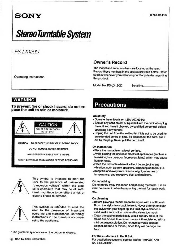
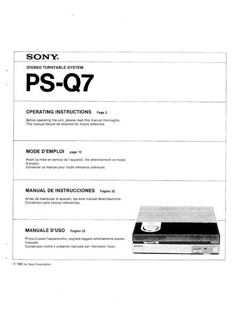
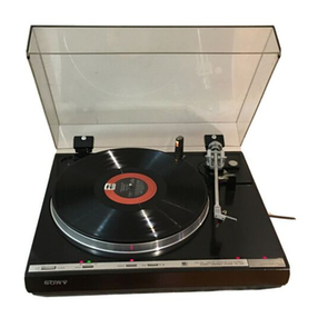
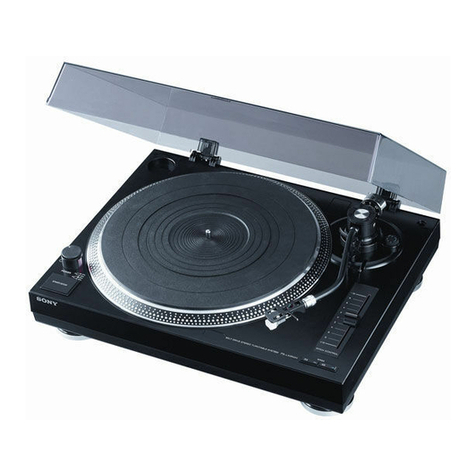
Sony PS-X50 Setup guide

SON
Yo
STEREO
TURNTABLE
SYSTEM
PS-X50
Owner’s
instruction
manual
page
2
Before
operating
your
new
Sony
turntable,
please
read
this
manual
completely
to
become
familiar
with
all
its
features
and
capabilities.
Keep
this
manual
handy
for
future
reference.
Mode
d’emploi_
page
12
Avant
de
faire
fonctionner
l'appareil,
lisez
attentivement
ce
mode
d’emploi
pour
se
familiariser
avec
toutes
ses
caracté-
ristiques.
Conservez
ce
manuel
pour
toute
référence
ultérieure.
Bedienungsanleitung
Seite
22
Bevor
Sie
die
Anlage
in
Betrieb
nehmen,
lesen
Sie
bitte
diese
Bedienungsanleitung
volistandig
durch,
damit
Sie
mit
den
be-
sonderen
Einrichtungen
und
Méglichkeiten
Ihrer
neuen
Sony-
Klangeinheit
vertraut
werden.
Bewahren
Sie.diese
Anleitung
gut
auf,
um
spater
jederzeit
darin
nachschlagen
zu
kénnen.
Manual
de
instrucciones
pagina
32
Antes
de
manipular
su
nuevo
tocadiscos
Sony,
lea
por
favor
de-
tenidamente
este
manual
a
fin
de
familiarizarse
con
todas
las
particularidades
y
capacidades
del
mismo.
Conserve
este
manual
para
futuras
referencias.
©
1978
by
Sony
Corporation

English
FEATURES
@The
X’tal
lock
system
maintains
the
turntable
at
an
accurate
nominal
speed
under
voltage
or
temperature
variations
or
aging,
and
shows
excellent
initial
drift
and
load/speed
characteristics.
@
Direct
drive
system
with
the
Sony’s
unique
linear
BSL
(brush-
less
and
slotless)
motor,
resulting
in
extremely
smooth
torque
and
start-up
characteristics.
@High
precision
speed
monitoring
system,
utilizing
5-pole
mag-
netic
pick-up
head
and
pulse
coated
platter
rim
for
electronic
speed
sensing.
@The
J-shaped
tonearm
using
a
long
span
trunnion
perform
sen-
sitively
and
is
adjustable
in
height
to
adapt
any
cartridge.
The
supplied
lightweight
aluminum
alloy
headshell
is
connected
firm-
ly
to
the
shell
from
plug
from
four
directions
by
the
newly
developed
locking
collar.
e@Control
switches
located
on
front
of
base,
permit
dust
cover
to
remain
closed
during
operation.
@
The
cabinet
made
from
a
special
inorganic
(non-plastic)
molded
compound
with
low
“Q”
and
newly
developed
resilient
feet
ef-
fectively
minimize
outside
vibrations
and
eliminate
acoustic
feed-
back.
TABLE
OF
CONTENTS
PrOCAUtIONS:
6.25
win
8.6
se
Oe
toe
Ye
eee
eR
2
Noteson,
installation:s
i...
668
wis coe
oe
we
ew
3
Operatihig:
VOAGE
oo
sssecse
geist
sa)
ie
kaw
Grate”
Sve
es
ee
ee
4
Partéidentification:s:
i
ite
as
Swe
eee
eS
OS
4
Turntable
assembly.
....
2...
..
2...
ee
ee
eee
5
Cartridge
installations.
«6
<i
6
<a
4
es
Bw
s,
Se
ws
5
Tonearm
assembly
and
adjustment.
............
6
Conhections
yaw
oes
ACRE
ew RE
ORS
BE
RS
8
RECO
PAYING)
0
6
sv
Geese
ar
te
weep
Cen
sanes
ele
Ge
dos
Woe!
We
9
Tips
on
record
handling!
¢.
646.6
66
a
woe
ae
sere
2
es
10
Maintenances:
occ
ee
eke
ee
oes
BAL
ew
10
Repacking
for
shipment
............+.22e0085
10
Specifications:
s.6
5% 2%
wil
Se Ra
sie
SK
SPS
RGD
S
10
TKOUDIOLONEOKG
6
5.5
sy
hse
Give
a
/en
voy»
coh
tote!
EGY
Sadia
Gr
11
WARNING
@To
prevent
fire
or
shock
hazard,
do
not
expose
the
unit
to
rain
or
moisture.
@To
avoid
electrical
shock,
do
not
open
the
cabinet.
servicing
to
qualified
personnel
only.
Refer
PRECAUTIONS
@
Check
that
the
operating
voltage
for
your
unit
is
identical
with
that
of
your
local
power
supply.
@
Should
any
liquid
or
solid
object
fall
into
the
cabinet,
unplug
the
unit
and
have
it
checked
by
qualified
personnel
before
operating
it
any
further,
@
Unplug
the
unit
from
the
wall
outlet
if it
is
not
to
be
used
for
an
extended
period
of
time.
To
disconnect
the
cord,
pull
it
out
by
grasping
the
plug.
Never
pull
it
out
by
the
cord.

NOTES
ON
INSTALLATION
OPERATING
VOLTAGE
@Place
the
turntable
on
a
level
surface.
Before
connecting
the
unit
to
the
power
source,
check
that
the
@
Avoid
placing
the
unit
near
electrical
appliances
(such
as
a
voltage
selector
setting
is
correct
for
your
power
supply.
If
the
television,
hair
dryer,
or
fluorescent
lamp)
which
may
cause
hum
selector
must
be
reset,
disconnect
the
ac
power
cord
and
set
or
noise.
the
selector
to
the
proper
voltage
using
a
screw
driver.
@
Avoid
any
vibration
such
as
from
speakers,
slamming
of
doors,
(The
voltage
selector
is
located
at
the
rear
panel.)
etc.
@
Keep
the
unit
away
from
direct
sunlight,
extremes
of
tempera-
ture,
or
excessive
dust
and
moisture.
g
120(__[}220
@Allow
10cm
(4
inches)
clearance
behind
the
unit
so
that
the
cover
can
be
opened.
@The
turntable
has
resilient
feet
that
isolate
the
mechanism
from
external
shock
and
vibration.
Use
them
in
locked
position,
but
when
placing
the
turntable
on
an
uneven
surface,
turn
each-
foot
until
the
unit
is
level.
Resilient
Foot

PARTS
IDENTIFICATION
The
picture
below
shows
the
appearance
of
the
assembled
turntable.
Rubber
Mat
Center
Spindle
45-rpm
Adaptor
Shell
Stand
Resilient
Foot
Power
Switch
Cueing
Lever
Speed
Selectors
Start/Stop
Button
Stroboscope
Reject
Button
Counterweight
Tonearm
Platform
Height
Adjustment
Knob
Tracking-force
Ring
Tonearm
Platform
Tonearm
Height
Adjustment
Konb
Arm
Rest
Height
—Anti-skating
Adjustment
Knob
Compensator

TURNTABLE
ASSEMBLY
Do
not
connect
the
power
cord
or
the
connecting
cords
until
after
finishing
the
assembly.
Remove
all
packing
material
and
clean
the
cabinet.
@
Remove
the
red-painted
transit
screws.
Save
these
screws,
since
they
will
be
required
when
repacking.
@
Carefully
place
the
platter
on
the
motor
board
by
matching
the
center
hole
and
the
center
spindle.
@Do
not
touch
the
magnetic
coating
with
your
fingers
or
damage
the
magnetic
pick-up
head.
©
Place
the
rubber
mat
on
the
platter.
To
remove
the
dust
cover
Open
the
dust
cover
fully
and
slide
it
as
illustrated
while
holding
it
with both
hands.
CARTRIDGE
INSTALLATION
For
the
customers
who
purchased
the
non-European
model:
Please
skip
this
section
and
proceed
with
the
following
tonearm
assembly
and
adjustment.
A
cartridge
weighing
up
to
8.5
g
can
be
mounted
with
the
sup-
plied
shell.
Heavier
cartridges
from
8
to
16.5g
can
be
mounted
using
the
extra
weight
(supplied).
@
Install
the
cartridge
into
the
shell
with
the
supplied
mounting
screws
so
that
the
distance
between
the
shell
end and
the
stylus
tip
is
approx.
49
mm
(1
15/16
inches),
The
temporary
overhang
adjustment
is
then
complete.
More
precise
adjustment
should
be
made
later.
;-———~
Fasten
the
screws
lightly
so
that
the
cartridge
can
slide
for
adjustment.
approx.
49
mm
(115.
inches)
@
Connect
the
lead
wires
of
the
shell
to
the
corresponding
pins
on
the
cartridge.
Wires
Cartridge
pins
White
.
cis
ae
eee
ne
L
(left
channel
signal)
Ble:
sc
wicete.W
pede
wae
LE
or
G
(left
channel
ground)
Rede
<2
nese
pieew
oe
R
(right
channel
signal)
Gree,
é.atece.s
Katerice
So
RE
or
G
(right
channel
ground)
@A
shell
stand
is
provided
on
the
base
of
the
turntable
for
an
extra
mounted
cartridge.

TONEARM
ASSEMBLY
AND
ADJUSTMENT
Do
not
connect
the
power
cord
or
the
connecting
cords
until
the
assembly
and
adjustments
are
complete.
The
following
procedures
should
be
performed
on
a
level
surface.
Be
careful
not
to
damage
the
stylus
tip
while
making
adjust-
ments.
When
a
cartridge
is
replaced,
readjustments
are
required.
Preparation
@
Secure
the
Tonearm
to
the
Arm
Rest
and
set
the
Cueing
Le-
verto[
¥
].
@
Plug
the
Shell
into
the
Tonearm
and
turn
the
Locking
Collar
counterclockwise
until
the
Shell
is
firmly
locked.
@
Insert
and
turn
the
Counterweight
counterclockwise
several
turns.
(The
Tracking-force
Ring
turns
simultaneously.)
Arm
Rest
Counterweight
To
use
a
cartridge
weighing
between
8—
16.5g,
add
the
supplied
extra
weight
Be
sure
to
insert
the
extra
weight
fully
to
the
end
Cueing
Leve
@
Remove
the
stylus
guard,
if
fitted.
Longitudinal
balance
adjustment
*1
@
Be
sure
that
the
Anti-skating
Compensator
is
set
at
“O”.
Release
the
Tonearm
from
the
Arm
Rest.
Anti-skating
compensator
"0"
@
Turn
the
Counterweight
as
required
until
the
Tonearm
is
in
a
horizontally
balanced
position.
Release
your
fingers
and
check
the
balance.
Repeat
this
step
until
the
arm
balances
pres
BG
Correct
balance
BZ
i
Move
the
weight
forward
©
While
holding
the
Counterweight
at
the
balanced
position,
separately
turn
the
Tracking-force
Ring
until
the
“O”
indication
meets
the
center
line
on
the
Tonearm.
Recheck
the
balance.
Move
the
weight
backward
Center
line
Do
not
move
the
counterweight
Tracking-force
Ring
@
Secure
the
Tonearm
to
the
Arm
Rest
again.
Tracking-force
adjustment
*2
Turn
the
Counterweight
counterclockwise
so
that
the
recom-
mended
tracking-force
figure
for
your
cartridge
is
aligned
with
the
center
line
on
the
Tonearm.
The
maximum
tracking
force
available
is
2,5
grams.
Tracking-force
ring
will
—
turn
at
the
same
time
Overhang
check
*3
For
the
customers
who
purchased
the
non-European
model:
Please
skip
this
section
and
proceed
with
the
following
anti-
skating
compensation.
Check
that
the
stylus
overhang
is
set
correctly
by
using
the
“235”
Alignment
Protractor
on
the
back
of
the
rubber
mat.
@
Place
the
rubber
mat
upside
down.
@
Bring
the
Tonearm
above
the
cross
point
of
the
two
fine
lines,
and
carefully
lower
the
stylus
on
the
cross
point
with
the
Cueing
Lever.
@
Check
to
see
that
the
Shell
is
parallel
to
the
lines
drawn
on
the
rubber
mat
as
shown
in
the
center
illustration.
If
they
are
parallel,
the
stylus
overhang
is
set
correctly.

Overhang
oO
is
too
long
Slide
the
cartridge
backward
—+—Correct
Overhang
is
too
short
Slide
the
cartridge
forward
Anti-skating
compensation
*4
Turn
the
Anti-skating
Compensator
so
that
the
guide
mark
is
aligned
with
the
tracking-force
value
used.
——
Anti-skating
Compensator
Tonearm
height
adjustment
@
Place
a
record
on
the
platter
and
lower
the
cartridge
onto
a
record.
@
Release
the
Tonearm
Height
Adj.
Knob
toward
you
and
move
it
in
the
required
direction
so
that
the
tonearm
becomes
parallel
to
the
turntable.
@
Calibration
is
in
mm,
©
When
the
adjustment
is
complete,
lock
the
Knob.
@
Lift
up
the
Tonearm
from
the
record
surface
by
setting
the
Cueing
Lever
to
the[
¥
]
position.
Be
sure
that
the
distance
be-
tween
the
stylus
tip
and
the
record
is
5
to
10mm.
If
not,
adjust
the
height
of
the
Tonearm
Platform
by
loosing
its
screw
as
illustrated.
Adjust
so
that
the
Tonearm
Platform
do
not
swerve
from
a
concentric
circle.
Arm
Rest
height
adjustment
When
the
Tonearm
height
is
changed,
the
Arm
Rest
height
adjustment
is
also
required.
@
Be
sure
that
the
Tonearm
Platform
is
up.
@
Pull
up
the
upper
portion
of
the
Arm
Rest
and
turn
it
clock-
wise.
Place
the
Tonearm
on
the
Arm
Rest.
®
Loosen
the
screw
so
that
no
clearance
is
left
between
the
Tonearm
and
the
Arm
Rest.
Retighten
the
screw.
*1
Longitudinal
balance
adjustment
While
playing
the
record,
the
weight
of
the
tonearm
is
supported
by
the
arm
pivot
and
only
tracking
force
is
applied
to
the
stylus
tip.
To
accomplish
this,
the
tonearm
must
first
be
balanced
horizontally,
with
the
tracking
force
indicator
set
at
“O”.
*2
Tracking
force
After
the
longitudinal
balance
adjustment,
apply
the
recommended
tracking
force
weight
so
that
the
stylus
tip
will
trace
the
music
groove
accurately.
*3
Overhang
In
record
playing,
because
of
the
pivoted
design
of
the
tonearm,
the
stylus
tip
can
be
perfectly
tangent
to
the
music
groove
at
only
one
point
of
the
record.
At
all
other
portions
of
the
record,
there
is
a
slight
deviation
of
the
stylus
from
tangency.
This
is
called
the
tracking
error,
and
introduces
minute
errors
in
the
amplitude
and
timing
of
the
reproduced
signal
as
compared
to
the
original,
and
other
forms
of
distortion
which
may
be
introduced
depending
on
the
cartridge
and
stylus
design.
Tracking
error
is
minimized
by
the
selection
of
an
optimum
“off-set”
angle
and
“overhang”
distance.
Overhang
is
the
distance
between
the
stylus
tip
and
the
center
spindle.
This
overhang
adjustment
is
made
at
the
time
of
installing
a
particular
cartridge,
while
the
off-set
angle
is
fixed
by
the
manufacturer
of
the
tonearm.
*4
Anti-skating
compensation
While
the
record
is
being
played,
the
frictional
force
between
the
record
groove
and
the
stylus
produces
a
force
that
tends
to
drive
the
tonearm
toward
the
center
of
the
record.
The
anti-skating
compensation
cancels
the
above
mentioned
force,
and
is
applied
in
accordance
with
the
tracking
force.
Incorrect
anti-skating
compensation
results
in
sound
distortion
and
uneven
wear
on
both
the
stylus
and
the
record.

CONNECTIONS
eCheck
that
the
phono
cord
and
power
cord
are
not
caught
under
any
foot
of
the
cabinet.
@Leave
a
little
slack
in
the
connecting
cord
to
allow
for
inad-
vertent
shock
or
vibration.
bos
power
cord
phono
cord
to
an
ac
outlet
to
phono
inputs
white...
to
L
PHONO
L
R
red.....
toR
pF
ahr
ground
wire
to
a
ground
rear
view
of
amplifier
terminal
RECORD
PLAYING
Follow
in
sequence
the
numbered
operations
of
the
diagram.
@
Push
the
POWER
Switch.
@
Place
a
record
on
the
platter.
@For
17cm
(7-inch)
records,
put
the
supplied
45-rpm
adaptor.
©
Push
the
SPEED
Button
(“33"-
or
“45”-rpm)
according
to
the
record
speed.
©
Remove
the
stylus
guard
while
keeping
the
Tonearm
on
the
Arm
Rest.
©
Set the
Arm
Rest
as
illustrated.
@
Set the
Cueing
Lever
to
[
¥
].
@
Push
the
START/STOP
Button,
LED
Lamp
illuminates.
©
Bring
the
Tonearm
above
the
lead-in
groove
of
the
record.
©
Set
the
Cueing
Lever
to
[
w
].
The
Tonearm
will
lower
on
the
record
and
playing
will
begin.
@
When
the
Tonearm
reaches
the
end
of
the
record,
it
will
auto-
matically
rise
and
return
to
the
Arm
Rest,
and
the
turntable
will
stop.

To
stop
during
play
Push
the
REJECT
Button.
to
the
Arm
Rest.
The
Tonearm
automatically
returns
@To
lift
up
the
Tonearm
manually,
use
the
Cueing
Lever
(see
“Cueing
lever’).
NOTES
elf
you
bring
the
Tonearm
too
near
the
label
of
the
record
while
the
turntable
is
rotating,
the
Tonearm
may
return
to
the
Arm
Rest
as
a
result
of
having
activated
the
automatic
return
mechanism.
@Do
not
push
the
REJECT
button
when
the
Tonearm
is
locked
on
the
Arm
Rest.
Cueing
lever
This
lever
is
used
to
lower
the
Tonearm
when
playing,
or
to
raise
the
Tonearm
manually
during
play
or
to
change
the
lis-
tening
point.
Stroboscope
and
neon
lamp
The
Crystal
Lock
System
assures
precise
turntable
speed.
This
is
verified
by
viewing
the
neon
lamp
stroboscope
pattern,
which
will
appear
stationary
at
the
correct
speed.
The
upper
line
is
for
45rpm
and
the
lower
for
33
1/3
rpm.
@The
neon
lamp
is
energized
by
a
120
Hz
pulse
from
the
built-
in
crystal
oscillator
and
assures
precise
speed
indication
regard-
less
of
any
line-frequency
deviation.
TIPS
ON
RECORD
HANDLING
Before
playing
@
Clean
the
stylus,
using
a
soft
brush
(stylus
brush,
artist’s
paint
brush,
etc).
Brush
the
stylus
from
back
to
front.
Never
attempt
to
clean
the
stylus
with
your
finger
tip.
@For
routine
cleaning
of
records,
the
use
of
a
barely
damp
soft
cloth
(gauze,
etc.)
or
a
fluid
type
cleaner
will
be
effective.
If
a
spray
type
record
cleaner
is
used,
make
sure
that
the
cleaner
has
dried
completely
before
playing
the
records.
Playing
the
record
before
the
fluid
has
dried
may
damage
the
record.
It
is
a
good
idea
to
clean
the
record
again
before
putting
it
away.
@
Handle
a
record
by
its
edges
and
don’t
touch
the
music
grooves.
Finger
prints
on
the
record
surface
may
induce
an
accumulation
of
dust,
resulting
in
impaired
tone.
When
record
playing
@
It
is
recommended
that
you
reduce
the
amplifier
volume
before
you
lower
the
tonearm
onto
the
record.
e@While
the
turntable
is
energized,
don't
attempt
to
stop
or
reverse
the
turntable
by
hand.
e@During
play,
be
sure
to
close
the
dust
cover.
anything
on
the
dust
cover.
e@While
playing,
never
attempt
to
move
the
turntable
or
touch
the
tonearm.
Don't
place
After
playing
@
Avoid
exposing
records
to
any
source
of
heat,
such
as
direct
sunlight,
a
hot-air
duct,
etc.
Store
records
vertically
without
ap-
plying
any
pressure
or
inclining
to
either
side.
This
will
minimize
any
warpage.
e@When
not
using
the
turntable,
close
the
dust
cover.
Other
precautions
@Don’t
put
anything
but
records
on
a
turntable.
@Don't
place
anything
but the
spare
cartridges
and
45-rpm
adaptor
on
the
turntable
deck.

MAINTENANCE
@Clean
the
cabinet
and
dust
cover
periodically
with
a
soft
dry
cloth.
Do
not
use
solvents
such
as
alcohol,
benzine
or
thinner,
since
they
will
damage
the
finish.
@When
the
rubber
mat
becomes
dirty,
wipe
it
gently
with
a
soft
cloth
slightly
dampened
with
water.
@No
lubrication
is
required
for
this
turntable.
The
motor
shaft
is
factory
lubricated
for
the
life
of
the
turntable.
REPACKING
FOR
SHIPMENT
The
original
shipping
carton
and
packing
material
(which
we
asked
you
to
save)
are
the
ideal
container
for
use
in
shipping
the
unit
for
repair
work,
or
to
another
location.
To
secure
the
maximum
protection,
it
must
be
repacked
in
this
material
pre-
cisely
as
before.
The
proper
repacking
procedure
is
shown
in
the
illustration.
@Clip
the
tonearm
to
the
arm
rest
and
bind
it
there
with
a
tape.
@Fasten
the
transit
screws
in
their
original
position
by
referring
to
the
illustration
of
“TURNTABLE
ASSEMBLY”
to
secure
the
inside
parts
to
the
cabinet.
Turn
the
screws
fully
clockwise.
10
SPECIFICATIONS
Turntable
Platter
32cm
(12
5/g
in.),
aluminum-alloy
diecast
Motor
Linear
BSL
(brushless
and
slotless)
motor
Drive
system
Direct
drive,
crystal
lock
control
system
Speed
33
1/3rpm,
45
rpm
Starting
characteristics
Comes
to
nominal
speed
within
a
second
revolution
(33
1/3
rpm)
+0.045%
(DIN)
0.025%
(WRMS)
75
dB
(DIN-B)
0%
at
150g
tracking
force
return,
reject
Wow
and
flutter
Signal-to-noise
ratio
Load
characteristics
Automatic
system
Tonearm
Type
Statically
balanced,
universal
Pivot-to-stylus
length
235mm
(9
1/4
in.)
Overall
arm
length
330
mm
(13
in.)
Overhang
14mm
(9/16
in.)
Tracking
error
+2°27'
—1°30'
Tracking
force
adjustment
range
0-2.5g
Shell
weight
11g
Cartridge
weight
range
(including
shell
weight)
11-19.5g
19-27.5g
(with
extra
weight)
General
Power
requirements
Power
consumption
120,
220V
ac~
adjustable,
50/60
Hi
12W
Dimensions
Approx.
480x165x420
mm
(w/h/d)|
(18
18/16
x
6
1/2x
16
8/16
in.)
including
projecting
parts
and
controlfi
Weight
Approx.
11.5kg
(25
lbs
6
oz),
net
Approx.
13kg
(28Ibs
11
02),
in
shipping
carton
45-rpm
adaptor
Shell
Extra
weight
Supplied
accessories
Whilst
the
information
given
is
trué
at
the
time
of
printing,
smi
production
changes
in
the
course
of
our
company’s
policy
|
improvement
through
research
and
design
might
not
necessarl
be
indicated
in
the
specifications.
We
would
ask
you
to
check
with
your
appointed
Sony
dealer,
clarification
on
any
point
is
required.

TROUBLE
CHECKS
The
following
chart
will
help
correct
most
problems
which
may
occur
with
the
unit.
If
the
problem
persists
after
you
have
made
these
checks,
consult
your
Sony
Service
Station
or
Sony
dealer.
Impaired
tone
quality
@Turntable
not
level
@Unit
incorrectly
placed
on
or
near
a
speaker
e@
Dusty
stylus
@
Worn
stylus
or
defective
record
(The
stylus
life
is
approx.
400
hours
of
playing
time.)
e@lncorrect
cartridge
installation
@improper
tonearm
balance
@improper
tracking
force
elmproper
setting
of
the
Anti-skating
Compensator
@Improper
turntable
speed
No
audio
from
one
channel
@
Loose
attachment
of
the
shell
to
the
tonearm
@Loose
connection
of
phono
cord
@Low
volume
level
setting
for
one
channel
of
the
amplifier
e@lncorrect
connection
of
the
shell
lead
wires
Groove
skipping,
Tonearm
tends
to
skate
out,
Tonearm
does
not
advance
(record
repeats)
e@Turntable
not
level
@
Defective
record
e@
External
vibrations
@Iimproper
tracking
force
@lmproper
setting
of
the
Anti-skating
Compensator
Steady
low-pitched
sound
(hum)
@Loose
ground
wire
connection
to
the
amplifier
@Loose
connection
between
the
shell
and
the
tonearm
e@lncorrect
connection
of
the
shell
lead
wires
@Transit
screws
not
removed
Loud
rumble
or
low-frequency
‘‘howl’’
which
occurs
when
playing
a
record
at
high
sound
levels
(acoustic
feedback*)
@Put
the
turntable
on
a
sturdy
surface.
@Put
the
turntable
as
far
away
from
the
speakers
as
possible.
elf the
above
does
not
rectify
the
problem,
try
commercially
available
acoustic
insulators
designed
to
be
put
between
the
feet
and
shelf.
*
Acoustic
feedback:
The
vibration
of
speakers
is
transmitted
through
the
air
or
via
solid
objects
(shelves, cabinets,
floor,
etc.)
to
the
turntable,
picked
up
by
the
cartridge
stylus,
amplified,
and
again
reproduced
through
the
speakers.
11

BESONDERE
MERKMALE
@Das
Quarzkontrollsystem
(crystal
lock)
sorgt
fiir
prazise
(fest-
gelegte)
Nenndrehzahl
des
Plattentellers,
wird
durch
Spannungs-
und
Temperaturschwankungen
nicht
beeinflu8t
und
unterliegt
keinen
Alterungserscheinungen.
AuBerdem
besitzt
es
ausgezeich-
nete
Anfangsdrift
und
Last/Geschwindigkeits-Charakteristiken,
@Direktantriebssystem
mit
Sonys
einzigartigem
linearen
BNL-
Motor
(biirsten-
und
nutenlos),
das
ein
extrem
weiches
Drehmo-
ment
und
sanftes
Startverhalten
ergibt.
@Drehzahikontrollsystem
von
héchster
Prazision,
das
mit
einem
8-poligen
magnetischen
Abgreifkopf
und
einem
impulsbeschich-
teten
Plattentellerrand
zur
elektronischen
Drehzahliiberwachung
arbeitet.
e@Der
J-férmige
Tonarm
mit
langer
Lagerachse
sorgt
fir
hohe
Abtastempfindlichkeit.
Er
ist
in
der
Héhe
verstellbar,
um
die
Verwendung
jedes
Tonabnehmers
zu
ermdéglichen.
Der
mitgelie-
ferte
Leichtgewichts-Tonarmkopf
aus
Spritzgu8
einer
Aluminium-
legierung
ist
durch
die
neu
entwickelte
Uberwurfmutter
von
vier
Seiten
fest
mit
der
Halterung
verbunden.
@
Die
Anbringung
der
automatischen
Regelschalter
auf der
Front-
seite
der
Einheit
erlauben
den
Betrieb
bei
geschlossenen
Schutz-
deckel.
@Das
Gehause
ist
aus
einem
speziellen
anorganischen
Material
(kein
Plastik)
mit
niedrigem
Q-Faktor
gegossen
und
mit
neu
ent-
wickelten
elastisch-federnden
FiiBen
versehen,
um
den
Einflu8
auBerer
Vibrationen
zu
minimieren
und
akustische
Riickkopplun-
gen
auszuschalten.
INHALTSVERZEICHNIS
Zur
besonderen
Beachtung.
.............2046
22
Hinweise
zur
Aufstellung.
.............2.248
23
Betrisbsspannung:
3's
a
Mis
sek
ew
Hae
e
aoa
23
Bezeichnung
der
Teile....
6
se
wae
ewe
ee
ee
24
Zusemmenbau
des
Plattenspielers
.............
25
Einbau
eines
Tonabnehmers
.............044
25
Zusammenbau
und
Justierung
des
Tonarmes
.......
26
PSCHIGSSOS.:
.
esec
ere
eye
SAT
Gree.
2
we
Adee
Gray
Od
28
Abspielen
von
Schallplatten
.............004
28
Behandlung
von
Schallplatten
...............
29
Wartung
und
Pflege..
ww
ee
ee
ee
ee
30
Wiederverpacken
zum
Transport.
.............
30
Technische:
Daten:
..
swe
oc
ee
RRS
ESE
OS
30
StOrungsiberprifungen.
..............0008
31
22
VORSICHT
@
Um
die
Gefahr
eines
elektrischen
Schlags
oder
eines
Brandes
auszuschalten,
setzen
Sie
das
Gerat
weder
Regen
noch
extremer
Feuchtigkeit
aus.
@
Um
einen
elektrischen
Schlag
zu
vermeiden,
darf
das
Gehause
nicht
gedffnet
werden.
Uberlassen
Sie
jegliche
Reparatur
und
Wartung
nur
qualifiziertem
Personal.
ZUR
BESONDEREN
BEACHTUNG
@Vergewissern
Sie
sich,
ob
die
Betriebsspannung
Ihres
Gerates
mit der
6rtlichen
Netzspannung
Ubereinstimmt.
e@Sollte
Flissigkeit
oder
ein
Fremdkérper
in
das
Gerateinnere
gelangen,
entfernen
Sie
alle
Anschliisse
und
lassen
Sie
das
Gerat
von
einem
Fachmann
Uberpriifen,
bevor
Sie
es
weiter
benutzen.
@Ziehen
Sie
den
Netzstecker
aus
der
Steckdose,
wenn
das
Gerat
fiir
langere
Zeit
nicht
benutzt
wird.
Halten
Sie
das
Kabel
immer
am
Stecker
fest,
wenn
Sie
es
herausziehen.
Ziehen
Sie
niemals
am
Kabel.

HINWEISE
ZUR
AUFSTELLUNG
@Stellen
Sie
den
Plattenspieler
waagerecht
auf.
@Vermeiden
Sie
eine
Aufstellung
des
Gerates
in
der
Nahe
elek-
trischer
Gerate
(wie
Fernseher,
Haartrockner
oder
Leuchtstoff-
lampen),
die
Brummen
oder
Stérungen
verursachen
konnen.
@Stellen
Sie
es
nicht
dort
auf,
wo
es
Vibrationen
(z.B.
von
Lautsprechern,
zugeschlagenen
Tiiren
usw.)
ausgesetzt
werden
kénnte.
@Setzen
Sie
das
Gerat
nicht
direkter
Sonnenbestrahlung,
extre-
men
Temperaturen
oder
einem
UbermaB
an
Staub
oder
Feuch-
tigkeit
aus.
@Lassen
Sie
hinter
dem
Gerat
ca.
10cm
Platz,
um
den
Klar-
sichtdeckel
6ffnen
zu
kénnen.
450
mm
475
mm
Der
Plattenspieler
hat
elastisch-federnde
FuBe,
die
den
Mecha-
nismus
vor
StoBen
und
erschiitterungen
von
auBen
schitzen.
Lassen
Sie
sie
in
der
festgestellen
Position,
auBer
wenn
Sie
den
Plattenspieler
auf
einer
unebenen
Unterlage
aufstellen.
Drehen
Sie
dann
die
Fie
zur
Nivelierung,
bis
das
Gerat
waagrecht
steht.
elastisch-federnder
FuB
BETRIEBSSPANNUNG
Vor
dem
NetzanschluB
vergewissern
Sie
sich,
daB
der
Spannungs-
wahler
richtig
auf
Ihre
drtliche
Netzspannung
eingestellt
ist.
Falls
eine
Umstellung
notwendig
ist,
ziehen
Sie
das
Netzkabel
ab,
stellen
Sie
den
Spannungswahler
auf
die
richtige
Voltzahl
mit
einem
Schraubenzieher
um.
Der
Spannungswahler
befindet
sich
auf
der
Riickseite
des
Gerates.
23

BEZEICHNUNG
DER
TEILE
Die
nachfolgende
Abbildung
zeigt
den
zusammengebauten
Plattenspieler.
Gummimatte
Achsspindel
Mittelstiick
fiir
45
UpM-Platten
Tonarmkopfhalter
elastisch-federnder
FuB
Netzschalter
Tonarmlifthebel
Geschwindigkeitswahler
Start-
Stoptaste
Stroboskop
Reject-Taste
Gegengewicht
Justierknopf
fiir
eng
Tonarm-Liftplattehéhe
c«
Tonarm
Tonarmauflage
’ ,
Auflagekraft-Einstellring
Justierknopf
fiir
Tonarmhoéhe
Tonarm-Liftplatte
Justierknopf
fiir
Anti-Skating-Vorrichtung
Tonarmauflagehéhe
24

ZUSAMMENBAU
DES
PLATTENSPIELERS
SchlieBen
Sie
weder
das
Netzkabel
noch
die
Verbindungskabel
an,
bevor
Sie
den
Zusammenbau
beendet
haben.
Entfernen
Sie
alles
Verpackungsmaterial
und
saubern
Sie
das
Gehause.
Magnetischer
Kantenbelag
(Innenseite
des
Randes)
Magnetkopf
@
Entfernen
Sie
die
roten
Arretierschrauben.
Bewahren
Sie
diese
Schrauben,
da
sie
beim
Wiederverpacken
bendtigt
werden.
@
Setzen
Sie
den
Plattenteller
vorsichtig
auf
die
Motorplatte,
indem
Sie
die
Achsspindel
in
das
Loch
in
der
Mitte
bringen.
e@Beriihren
Sie
den
magnetischen
Kantenbelag
nicht
mit
den
Fingern
und
beschadigen
Sie
nicht
den
magnetischen
Abgreif-
kopf.
@
Legen
Sie
die
Gummimatte
auf
den
Plattenteller.
Abnehmen
des
Klarsichtdeckels
Offnen
Sie
den
Klarsichtdeckel
vollstandig,
indem
Sie
ihn
mit
beiden
Handen
halten,
und
schieben
Sie
ihn
wie
in
der
Abb.
gezeigt.
EINBAU
EINES
TONABNEHMERS
Besitzen
Sie
eine
Nichteuropaische-Ausfihrung,
so
Uberspringen
Sie
diese
Kapitel
und
fahren
mit der
anschlieBenden
,,Zusam-
menbau
und
Justierung
des
Tonarmes”
fort.
Ein
Tonabnehmer
mit
einem
Gewicht
mehr
als
8,5g
kann
mit
dem
mitgelieferten
Tonarmkopf
verwendet
werden.
Verwenden
Sie
fiir
schwerere
Tonabnehmer
von
8
bis
16,5
g
das
Zusatzgewicht
(mitgeliefert).
@
Installieren
Sie
den
Tonabnehmer
in
dem
Tonarmkopf
mit
den
mitgelieferten
Befestigungsschrauben
so,
daB
der
Abstand
zwi-
schen
Tonarmkopfende
und
Nadelspitze
ungefahr
49
mm
betragt.
Die
vorlaufige
Uberhangeinstellung
ist
damit
beendet.
Eine
genauere
Einstellung
sollte
spater
durchgefiihrt
werden.
r
——Ziehen
Sie
die
Schrauben
nur
so
leicht
an,
da®B
der
Tonabnehmer
zur
Justierung
verschoben
kann.
__ca.
49
mm_
@
SchlieBen
Sie
die
‘AnschluBdrahte
des
Tonarmkopfes
an
die
entsprechenden
Stifte
des
Tonabnehmers
an.
Drahte
Tonabnehmerstift
WWBIB
iio
detors.>
cows,
€
L
(Signal
des
linken
Kanals)
LGU
aeaiietis
-es:i9
a
deans
LE
oder
G
(Erde
des
linken
Kanals)
TOU
pats
£5
Gh
5
eahe
st
R
(Signal
des
rechten
Kanals)
TON
ices
avons
Saes-y
RE
oder
G
(Erde
des
rechten
Kanals)
@Ein
Tonarmkopfhalter
an
der
Oberseite
des
Plattenspieler-
gehauses
dient
zur
Aufbewahrung
der
zusatzlichen
Tonabneh-
mer.
25

ZUSAMMENBAU
UND
JUSTIERUNG
DES
TONARMES
SchlieBen
Sie
weder
das
Netzkabel
noch
sonstige
Verbindungs-
kabel
an,
bevor
der
Zusammenbau
und
die
Einstellungen
beendet
sind.
Fihren
Sie
die
folgenden
Arbeitsgange
auf
einer
waagrechten
Unterlage
aus.
Achten
Sie
beim
Einstellen
darauf,
die
Nadelspitze
nicht
durch
AnstoBen
zu
beschadigen.
Bei
einem
Wechsel
des
Tonabnehmers
sind
neue
Einstellungen
erforderlich.
Vorbereitung
@
Sichern
Sie
den
Tonarm
auf
seiner
Auflage
und
stellen
Sie
den
Tonarmlifthebel
auf
¥
.
@
Stecken
Sie
den
Tonarmkopf
auf
den
Tonarm
und
drehen
Sie
die
Uberwurfmutter
nach
links,
bis
der
Tonarmkopf
fest
verrie-
gelt
ist.
©
Schieben
Sie
das
Gegengewicht
auf
und
drehen
Sie
es
einige
Male
nach
links.
(Der
Auflagekraft-Einstellring
dreht
sich
gleich-
zeitig
mit.)
i
a
Gegengewicht
Um
einen
Tonabnehmer
mit
dem
Gewicht
zwischen
8~—16,5g
zu
verwenden,
bringen
Sie
das
mitgelieferte
Zusatzgewicht
an.
Achten
Sie
darauf,
das
Zusatzgewicht
ganz
bis
zum
Anschlag
einzuschieben.
Tonarmiifthebel
@
Entfernen
Sie
die
Nadelschutzkappe,
falls
aufgesetzt.
Einstellung
der
Tonarmbalance
*1
@
Achten
Sie
darauf,
daB
die
Anti-Skating-Vorrichtung
auf
,,0”
gestellt
ist.
Lésen
Sie
den
Tonarm
von
seiner
Auflage.
Ant
Skating
Vorrichtung
+”
@
Drehen
Sie
das
Gegengewicht,
soweit
erforderlich,
bis
der
Tonarm
in
der
horizontalen
Balancestellung
ist.
26
Lassen
Sie
den
Tonarm
los
und
Uberpriifen
Sie
die
Balance.
Wiederholen
Sie
diesen
Schritt,
bis
der
Arm
ausbalanciert
ist
Richtiges
Ausbalancieren
Schieben
Sie
das
Gewicht
nach
vorn.
Schieben
Sie
das
Gewicht
nach
hinten.
©
Wiahrend
Sie
das
Gegengewicht
in
der
Gleichgewichtstel-
lung
festhalten,
drehen
Sie
den
Auflagekraft-Einstellring
so,
daB
die
Nullmarke
,,0’’
mit
der
Mittellinie
auf
dem
Tonarm
zur
Deckung
kommt.
Uberpriifen
Sie
die
Balance
wieder.
Verstellen
Sie
nicht
das
Gegengewicht
Auflagekraft-Einstellring
@
Sichern
Sie
den
Tonarm
wieder
auf
der
Tonarmanflage.
Einstellung
der
Auflagekraft
*2
Drehen
Sie
das
Gegengewicht
gegen
den
Uhrzeigersinn,
bis
das
fiir
den
verwendeten
Tonabnehmer
empfohlene
Gewicht
Uber
der
Mittellinie
des
Tonarmes
steht.
Die
maximal
einstellbare
Auflagekraft
ist
2,5
Gramm.
Der
Auflagekraft-Einstellring
———_
dreht
sich
gleichzeitig
mit
Uberpriifung
des
Uberhangs*3
Besitzen
Sie
eine
Nichteuropaische-Ausfiihrung,
so
Uberspringen
Sie
diese
Kapitel
und
fahren
Sie mit
der
anschliBenden
,,
Anti-
Skating-Vorrichtung
“’
fort.
Uberpriifen
Sie,
ob
der
Uberhang
der
Nadel
richtig
eingestellt
ist.
Benutzen
Sie
dazu
den
235
Winkelmesser,
der
auf der
Riick-
seite
der
Gummimatte
ist.

Nadeliiberhang
°
ist
zu
lang
Schieben
Sie
den
Tonabnehmer
nach
:
Richtiger
Uberhang
(
Nadeliiberhang
ist
zu
kurz
Schieben
Sie
den
Tonabnehmer
nach
vorn.
Anti-Skating-Vorrichtung
*4
Drehen
Sie
die
Anti-Skating-Vorrichtung
so,
daB
ihre
Einstell-
marke
Uber
dem
Wert
der
erforderlichen
Auflagekraft
zu
stehen
kommt.
Justierung
der
Tonarmhéhe
@Legen
Sie
eine
Platte
auf
den
Plattenteller
und
senken
Sie
den
Tonabnehmer
ab.
@
Entriegeln
Sie
den
Justierknopf
fiir
die
Tonarmhdhe,
indem
Sie
ihn
in
Ihre
Richtung
drehen
und
stellen
Sie
dann
die
Ton-
armhéhe
so
ein,
da®
der
Tonarm
parallel
zur
Platte
steht.
@
Die
Skala
ist
in
mm
geeicht.
@
Nach
Beendigung
der
Einstellung,
verriegeln
Sie
den
Knopf
wieder,
@
Heben
Sie
den
Tonarm
von
der
Schallplattenoberflache
ab,
indem
Sie
den
Lifthebel
in
die
Position
[
¥
]
bringen.
Vergewissern
Sie
sich,
da®B
der
Abstand
zwischen
Nadelspitze
und
Schallplatte
5
bis
10mm
betragt.
Wenn
nicht,
justieren
Sie
die
Héhe
der
Tonarmliftplatte,
indem
Sie
ihre
Schraube
wie
in
der
Abbildung
gezeigt
lésen.
Achten
Sie
beim
Justieren
darauf,
daB
die
Liftplatte
in
ihrer
konzentrischen
Position
bleibt.
HGhenjustierung
der
Tonarmauflage
Bei
Anderung
der
Tonarmhohe
ist
eine
Justierung
der
Tonarm-
auflagenhodhe
ebenfalls
erforderlich.
@
Vergewissern
Sie
sich,
daB
die
Tonarmliftplatte
oben
ist.
@
Ziehen
Sie
den
oberen
Teil
der
Tonarmauflage
hoch,
und
drehen
Sie
ihn
nach
rechts.
Setzen
Sie
den
Tonarm
auf
die
Tonarmauflage.
©
Lésen
Sie
die
Schraube,
so
daB
kein
Zwischenraum
zwischen
Tonarm
und
Tonarmauflage
tbrigbleibt.
Ziehen
Sie
die
Schraube
wieder
fest.
*1
Einstellung
der
Tonarmbalance
Beim
Abspielen
einer
Schallplatte
wird
das
Gewicht
des
Tonarmes
durch
den
ausbalancierten
Drehpunkt
gehalten
und
nur
die
eingestellte
Auflagekraft
wirkt
auf
die
Spitze
der
Nadel.
Um
dies
zu
erreichen,
mu
der
Tonarm
horizontal
ausbalanciert
werden.
wobei
die
Auflagekraft
auf
..0’
gestellt
wird.
*2
Auflagekraft
Nach
dem
Einstellen
der
Tonarmbalance
stellen
Sie
die
empfohlene
Auflagekraft
ein,
damit
die
Spitze
der
Nadel
exakt
in
der
Fuhrungsrille
der
Schallplatte
lauft,
*3
Uberhang
Beim
Abspielen
von
Schallplatten
kann
die
Spitze
der
Nadel,
bedingt
durch
die
drehbare
Aufhangung
des
Tonarmes,
nur
an
einer
Stelle
der
Schaliplatte
exakt
tangential
in
der
Fuhrungsrille
liegen.
An
allen
anderen
Stellen
der
Schaliplatte
kommt
es
zu
leichten
Abweichungen
der
Nadel
von
der
tangentialen
Berithrung.
Dies
nennt
man
Spurenfehler,
und
dadurch
werden
kleine
Abweichungen
in
Amplitude
und
Schwingungszeit
des
wiedergegebenen
Signals
im
Vergleich
zum
Originalsignal
verursacht.
Je
nach
Art
des
Tonabnehmers
oder
der
Nadel
kénnen
dadurch
auch
andere
Arten
von
Verzerrungen
erzeugt
werden.
Der
Spurenfehler
wird
durch
die
Wah!
des
optimalen
.,Aufsetzwinkels’’
und
des
optimalen
Uberhangabstandes
auf
ein
MindestmaB
herabgesetzt.
Als
Uberhang
bezeichnet
man
den
Abstand
zwischen
der
Nadelspitze
und
der
Achsspindel.
Die
Uberhangjustierung
wird
beim
Einsetzen
des
jeweiligen
Tonabnehmers
vor-
genommen,
der
Aufsetzwinkel
ist
vom
Hersteller
des
Tonarmes
festgelegt.
*4
Anti-Skating-Vorrichtung
Beim
Abspielen
von
Schallplatten
erzeugt
die
Reibung
zwischen
Schallplattenrille
und
Nadel
eine
Kraft.
die
den
Tonarm
in
die
Mitte
der
Schallplatte
drucken
will.
Die
Anti-Skating-Vorrichtung
hebt
diese
Kraft
auf,
sie
ist
beim
Einstellen
der
Auflagekraft
mitbericksichtigt.
UnsachgemaBe
Anti-Skating-Kompensation
fuhrt
zu
Klangverzerrungen
und
ungleichmaBiger
Abnutzung
sowohl
der
Nadel
als
auch
der
Schallplatte.
27

ANSCHLUSSE
@Achten
Sie
darauf,
daB
Phono-
oder
Netzkabel
nicht
von
einem
GehausefuB
eingeklemmt
werden.
e@Wahlen
Sie
die
Verbindungskabel
nicht
zu
kurz,
um
unbeab-
sichtigte
StéBe
oder
Vibrationen
auszugleichen.
Netzkabel
Phonokabel
an
eine
Netzsteckdose
an
Phonoeingange|
weib
Erdungsdraht
an
einen
Rickansicht
des
Verstarkers
ErdungsanschluB
28
ABSPIELEN
VON
SCHALLPLATTEN
Folgen
Sie
den
Ziffern
der
Anweisung
im
Diagramm.
@
Driicken
Sie
den
Schalter
[POWER].
@
Legen
Sie
eine
Schallplatte
auf
den
Plattenteller.
@
Verwenden
Sie
fiir
17
cm-Schallplatten
das
mitgelieferte
Mittel-
stiick
fiir
45-UpM-Platten.
©
Entsprechend
der
erforderlichen
Plattengeschwindigkeit,
driik-
ken
Sie
die
Taste
[SPEED]
(,,33”-
oder
,45"-UpM).
©
Stellen
Sie
die
Tonarmauflage
wie
abgebildet
ein.
@
Stellen
Sie
den
Tonarmlifthebel
auf
©
@
Driicken
Sie
die
Taste
([START/STOP]}.
Die
LED-Lampe
leuch-
tet
auf.
©
Bringen
Sie
den
Tonarm
uber
die
Anfangsrille
der
Schallplatte
und
starten
Sie
somit
den
Plattenspieler.
©
Stellen
Sie
den
Tonarmlifthebel
auf
¥
.
Der
Tonarm
senkt
sich
auf
die
Schallplatte
ab
und
die
Wiedergabe
beginnt.
e@Erreicht
der
Tonarm
das
Ende
der
Schallplatte,
hebt
er
sich
automatisch
ab
und
kehrt
zu
seiner
Auflage
zuriick,
Der
Platten-
teller
wird
angehalten.

Zum
Stoppen
wahrend
dem
Abspielen
Driicken
Sie
die
Taste
[REJECT].
Der
Tonarm
kehrt
automa-
tisch
auf
seine
Auflage
zuriick.
@Zum
manuellen
Anheben
des
Tonarmes
verwenden
Sie
den
Tonarmlifthebel
(siehe
,,.
Tonarmlifthebel”).
HINWEISE
e@Wenn
Sie,
wahrend
sich
der
Plattenteller
dreht,
den
Tonarm
in
die
Nahe
des
Schallplattenetiketts
schieben,
kann
der
Tonarm
zur
Tonarmauflage
zuriickkehren,
weil
der
automatische
Riick-
kehrmechanismus
anspricht.
@Driicken
Sie
die
Taste
[REJECT]
nicht,
wahrend
der
Tonarm
auf
seiner
Auflage
arretiert
ist.
Tonarmlifthebel
Dieser
Hebel
wird
zum
Absenken
des
Tonarmes
zum
Abspielen
einer
Schallplatte
verwendet
oder
um
wahrend
des
Abspielens
den
Tonarm
manuell
anzuheben
und
auf
einer
anderen
Stelle
der
Schallplatte
abzusenken.
Stroboskop
und
Neonlampe
Die
Quarzregelung
(crystal
lock)
sorgt
fiir
prazise
Umdrehungs-
geschwindigkeit.
Dies
wird
bestatigt,
wenn
man
das
Strobo-
skopmuster
unter
der
Neonlampe
betrachtet.
Bei
der
korrekten
Geschwindigkeit
scheint
es
stillzustehen.
Die
obere
Reihe
gilt
fiir
45
UpM
und
die
untere
fiir
33
1/3
UpM.
@
Die
Neonlampe
wird
durch
den
eingebauten
Quarzoszillator
mit
einer
Pulsfrequenz
von
120
Hz
versorgt
und
somit
gewahrleistet
unabhangig
von
Netzfrequenzschwankungen
genaue
Geschwin-
digkeitsanzeige.
BEHANDLUNG
VON
SCHALLPLATTEN
Vor
dem
Abspielen
@Reinigen
Sie
die
Nadel
mit
einem
weichen
Pinsel
(Nadelpinsel,
Kunstmalerpinsel
usw.).
Streifen
Sie
damit
die
Nadel
von
hinten
nach
vorne.
Versuchen
Sie
nie
die
Nadel
mit
der
Fingerspitze
zu
reinigen.
@Fiir
die
gewdhnliche
Reinigung
von
Schallplatten
ist
ein
leicht
angefeuchtetes
weiches
Tuch
(Gaze
usw.)
oder
ein
flissiger
Plattenreiniger
zweckmaBig.
Wenn
ein
Sprihplattenreiniger
verwendet
wird,
so
iiberzeugen
Sie
sich,
daB
er
véllig
getrocknet
ist,
bevor
Sie
die
Schallplatten
abspielen.
Abspielen,
bevor
das
Reinigungsmittel
getrocknet
ist,
kann
die
Schallplatten
bescha-
digen.
Es
ist
vorteilhaft,
die
Schallplatten
vor
dem
Weglegen
erneut
zu
reinigen.
@
Halten
Sie
eine
Schallplatte
am
Rand
und
berihren
Sie
nicht
die
Schallrillen.
Fingerabdriicke
auf
der
Schallplattenoberflache
kénnen
Staubansammlung
verursachen,
welche
die
Wiedergabe
beeintrachtigen.
Beim
Abspielen
von
Schallplatten
@Es
wird
empfohlen,
vor
dem
Absenken
des
Tonarmes
auf
die
Schallplatte
die
Lautstarke
des
Verstaérkers
zu
verringern.
@Versuchen
Sie
nicht,
den
Plattenteller
anzuhalten
oder
gegen
den
Uhrzeigersinn
zu
drehen,
wahrend
der
Plattenspieler
einge-
schaltet
ist.
@SchlieBen
Sie
den
Klarsichtdeckel
beim
Abspielen.
nichts
auf
den
Klarsichtdeckel.
e@Versuchen
Sie
beim
Abspielen
nicht,
den
Plattenspieler
zu
bewegen
oder
den
Tonarm
zu
beriihren.
Legen
Sie
Nach
dem
Abspielen
@Vermeiden
Sie
es,
Schallplatten
irgendwelchen
Warmequellen
auszusetzen,
wie
etwa
direktem
Sonnenlicht,
einem
Warmluft-
strom
0.a..
Bewahren
Sie
Schallplatten
senkrecht
gestellt,
ohne
irgendwelchen
Druck
und
ohne
sie
schragzustellen
auf.
Dies
schitzt
sie
am
besten
vor
dem
Verziehen.’
@SchlieBen
Sie
den
Klarsichtdeckel,
wenn
Sie
den
Plattenspieler
nicht
verwenden.
Weitere
Hinweise
@Legen
Sie
nur
Schallplatten
auf
den
Plattenteller.
e@Legen
Sie
auBer
der
zusatzlichen
Tonabnehmern
und
dem
Mittelstiick
fir
45-UpM-Platten
nichts
anderes
auf
den
Platten-
spieler.
29

WARTUNG
UND
PFLEGE
@Reinigen
Sie
das
Gehause
und den
Deckel
regelmaBig
mit
einem
weichen,
trockenen
Tuch.
Benutzen
Sie
keine
chemischen
Reinigungsmittel
wie
Alkohol,
Benzin
oder
Farbverdinner,
da
diese
das
Gehause
beschadigen.
elst
die
Gummimatte
schmutzig
geworden,
reinigen
Sie
sie
vorsichtig
mit
einem
mit
Wasser
angefeuchteten
Tuch.
@Olen
ist
bei
diesem
Plattenspieler
nicht
erforderlich.
Die
Motor-
welle
ist
fabrikseitig
fiir
die
Gesamtlebensdauer
des
Gerates
gedit.
WIEDERVERPACKEN
ZUM
TRANSPORT
Der
Originalkarton
und
das
dazugehGérige
Verpackungsmaterial,
das
Sie
auch
aufbewahren
sollten,
sind
die
bestmégliche
Ver-
packung
fiir
den
Transport
des
Gerates
zur
Reparatur
bzw.
beim
Umzug
usw..
Um
jedoch
den
wirklich
besten
Schutz
zu
gewahr-
leisten,
muB
das
Geraét
in
diesem
Verpackungsmaterial
genau
wie
bei
der
Lieferung
verpackt
werden.
Der
richtige
Verpak-
kungsvorgang
ist
aus
der
Abbildung
ersichtlich.
@Sichern
Sie
den
Tonarm
auf der
Tonarmauflage
und
befestigen
Sie
ihn
mit
einem
Band.
@Befestigen
Sie
die
Arretierschrauben
in
ihrer
urspriinglichen
Stellung,
um
die
Teile
im
Innern
des
Gehauses
zu
sichern.
Drehen
Sie
die
Schrauben
nach
rechts
fest.
Beziehen
Sie
sich
auf
die
Abbildung
,,Zusammenbau
des
Platten-
spielers’’.
30
TECHNISCHE
DATEN
Laufwerk
Plattenteller
32cm,
Spritzgu8
aus
Alu-Legierung
Motor
Linear-BNL
(biirsten-
und
nutenlos)
Gleichstrom-Servomotor
Direktantrieb,
Quarzkontrollsystem
33
1/3
UpM,
45
UpM
nach
1/2
Umdrehung
auf
Nenndrehzahl
(bei
33
1/3
UpM)
Gleichlaufschwankungen
+0,045%
(DIN)
0,025%
(WRMS)
Signal-Rauschabstand
75 dB
(DIN-B)
Lastcharakteristik
0%
bei
150g
Auflagekraft
Automatisches
System
Ruickkehr,
Tonarmlift
Antriebssystem
Drehzahl
Anlaufzeit
Tonarm
Typ
Statisch
ausbalanciert,
universell
Lange
von
Lagerachse
bis
Abtastspitze
235
mm
Gesamtlange
330
mm
Uberhang
14mm
Spurfehlwinkel
+2°27’,
—1°30’
Justierbereich
fiir
Auflagekraft
0—2,5g
Gewicht
des
Tonarmkopfes
11g
Zulassiges
Gewicht
fiir
Tonabnehmer
(einschl.
Tonarmkopf)
11,0—19,5g
19,0--27,5
g
(mit
Zusatzgewicht)
Allgemeines
Stromversorgung
120,
220
V
Wechselspannung
einstellbar,
50/60
Hz
Leistungsaufnahme
12W
Abmessungen
ca.
480x
165x420
mm
(B/H/T)
einschl.
vorspringender
Teile
und
Bedienungselemente
Gewicht
ca.
11,5kg
netto
ca.
13kg
im
Versandkarton
Mitgeliefertes
Zubehér
Mittelstiick
fiir
45
UpM-Platten
Tonarmkopf
Zusatzgewicht
Anderungen,
die
dem
technischen
Fortschritt
dienen,
bleiben
vorbehalten.
Table of contents
Languages:
Other Sony Turntable manuals

Sony
Sony WALKMAN NW-ZX505 User manual

Sony
Sony PS-X6 Setup guide

Sony
Sony Walkman NW-HD1 User manual

Sony
Sony PS-J20 User manual

Sony
Sony PMW-PZ1 User manual

Sony
Sony PS-LX520 User manual

Sony
Sony PS-LX250H Parts list manual

Sony
Sony PMW-PZ1 User manual

Sony
Sony Walkman WM-EX600 User manual

Sony
Sony CDX-3002 User manual