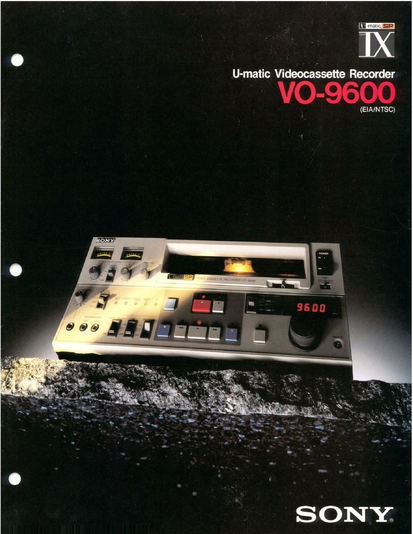
Sony VO-9600 User manual

MIMIN
so
VO9600
Avant
la
mise
en
aoe
cet
soa
priére
de
lire
attentivement
etl
©
1987
by
Sony
Corporation

OWNER’S
RECORD
The
model
and
serial
numbers
are
located
at
the
rear.
Record
the
serial
number
in
the
space
provided
below.
Refer
to
these
numbers
whenever
you
call
upon
your
Sony
dealer
regarding
this
product.
Model
No.
VO-9600
Serial
No.
Caution
Television
programmes,
films,
video
tapes
and
other
materials
may
be
copyrighted.
Unauthorized
recording
of
such
material
may
be
contrary
to
the
provisions
of
the
copyright
laws.
|WARNING
To
prevent
fire
or
shock
hazard,
do
not
ex-
pose
the
unit
to
rain
or
moisture.
CAUTION
RISK
OF
ELECTRIC
SHOCK
DO
NOT
OPEN
CAUTION
:
TO
REDUCE
THE
RISK
OF
ELECTRIC
SHOCK,
DO
NOT
REMOVE
COVER
(OR
BACK).
NO
USER-SERVICEABLE
PARTS
INSIDE.
REFER
SERVICING
TO
QUALIFIED
SERVICE
PERSONNEL.
This
symbol
is
intended
to
alert
the
user
to
the
presence
of
uninsulated
“dangerous
voltage”
within
the
prod-
uct’s
enclosure
that
may
be
of
suffi-
cient
magnitude
to
constitute
a
risk
of
electric
shock
to
persons.
This
symbol
is
intended
to
alert
the
user
to
the
presence
of
important
operating
and
maintenance
(servicing)
instructions
in
the
literature
accompa-
nying
the
appliance.
WARNING
This
equipment
generates,
uses,
and
can
radiate
radio
frequency
energy
and
if
not
installed
and
used
in
accordance
with
the
instructions
manual,
may
cause
interference
to
radio
communications.
It
has
been
tested
and
found
to
comply
with
the
limits
for
Class
A
computing
devices
pursuant
to
Subpart
J
of
Part
15
of
FCC
Rules,
which
are
designed
to
provide
reasonable
protection
against
such
interference
when
operated
in
a
commercial
environment.
Operation
of
this
equipment
in
a
residential
area
is
likely
to
cause
interference
in
which
case
the
user
at
his
own
expense
will
be
required
to
take
whatever
measures
may
be
required
to
correct
the
interference.
The
shielded
interface
cable
recommended
in
this
manual
must
be
used
with
this
equipment
in
order
to
comply
with
the
limits
for
a
computing
device
pursuant
to
Subpart
J
of
Part
15
of
FCC
rules.

GOMOM
A
2h.
scscescsSsnnncscaceeciassCercsivadevastesdeecuesteteascsdinwscsstedtaveties
4
About
frame
codes
ww
4
PHO
CAUTIONS
scoscccccitescve
de
icnsccnecesesectecinsstucuadonteticenturterteonesctenss
5
New
recording/playback
system
(SP
system)
............
6
Functions
of
parts
and
controls
Front
panel
scicicevec
eta
ee
ee
als
8
Rear
panel
esses
asthe.
tes
ceases
enacts
cceshadean
ncanssuveecs
12
Connections
For
camera
recording
For
tape
CUDDING
........csssccsesssessscscsnsesneesneessscaeesensenteereaes
For
connecting
a
video
monitor
with
an
8-pin
Video
Cable
.......esesceeceeeeeeees
ws
sdtauaglaadescauscensacasceceecewcests
15
For
connecting
a
video
monitor
not
having
an
B-PIN
VTR
COMMECEON
oes
eeseseeseeceetseeeeeoneeeeenanseeenens
15
For
connecting
a
TV
receiver
..............:+
a
16
For
connecting
a
stereo
system
.............
.
16
For
microphone
recording
..........sscscsesecsceeeee
wn
(7
For
sound
monitoring
through
headphones
..........
17
POWET
CONNECTION
.......ccssscecssessecsnenessecesessccteneceeatatareerenes
17
On
video
cassettes
TO
INSert
A
CASSEHES
on...
sesssceeseeeeseeseeeeteseeeeteeetenesenses
18
To
insert
a
small-size
(KSP-S
or
KCS)
cassette
.....
18
TO
FEMOVE
A
CASSEHHE
«......aeeeeeeeeceecsesceesececeecetoeseenenteneees
18
Recording
PLEPATALIONS
cseccscsacssusectssstnistsesssataceatsiesvssnsceacevtiavenvedscaste
Operation
......sssssscccsssersossnescseessnsesssesseeeesseesnees
To
monitor
the
sound
being
recorded
.......
TO
GUD
QUGIO
..0.....eesescnessneecnteretentecneresesonseseensenes
To
record
sound
on
the
middle
of
a
tape
wate
EFASHING)
wvsccnenseniscssosicnssdisnssccsisesaiensscasctensisstcesdestecasactcavecesiee
Playback
Preparations
Operation
..........ce
Search
operation
Programmed
Operation...
Playback
using
a
time
base
corrector
Timer
recording/PlayDack
........sssscsesssessseseeseeees
Connections
iki
Operation
tscenic5,
seni
eaten
To
view
a
playback
picture
on
a
TV
receiver
Installation
of
an
RF
MOCUuIator
......eseeeseseeeseeesees
34
Connections
we
4
OPS
AION
sos.
cscccesecosiscsccectniicecdtcccsnacesisnssrecousrtvedesbesstactseasees
35
Remote
control
operation
Using
a
remote
Control
UNIt
ose
eseesecteeesneenensnenees
36
Using
an
RX-353
or
RX-303
automatic
search
COMTPOD
UIE:
sc
crsceceaenccccccescscnectzateteasentatecttcaici
ie
deeucandeiaatay
37
Using
an
RX-707
automatic
search
control
unit
....
38
Connection
of
&
COMPUTET
ou...
eecececseseceseeeceeseeeeees
39
Rack
mounting
SPecifiCatiOns
2...
ecescsescesessestseesenestecetsseseessesesssenessaeseeeees
Troubleshooting
sie’
Video
NEA
CLEANING
..........esessectscessssteseeesecenseeereceeeeeees
42
Video
head
replaceMeNt
..........ccesssesssesessessesssneeees
4
High-quality
picture
with
a
new
recording/playback
system
Recording
and
playback
using
the
newly
developed
SP
(Superior
Performance)
system
and
SP
tapes
specially
designed
for
the
SP
system,
provide
clearer
and
sharper
pictures
than
before.
Hi-Fi
sound
Dolby
NR*
C
type
noise
reduction
system
permits
high-
performance
audio
recording/playback
with
reduced
noise
(With
Dolby
NR
on.
S/N
70dB
with
KSP
or
KSP-S
tape).
Cannon
3-pin
connectors
usually
used
for
professional
audio
equipment
are
employed
for
the
audio
inputs
and
outputs.
*
Dolby
noise
reduction
manufactured
under
license
from
Dolby
Laboratories
Licensing
Corporation.
“DOLBY”
and
the
double-D
symbol
D0
are
trademarks
of
Dolby
Laboratories
Licensing
Corporation.
RS-232C
interface
A
simple
circuit
board
replacement
provides
an
RS-232C
interface,
which
permits
remote
control
operations
from
an
optional
search
control
unit,
such
as
the
Sony
RX-707,
or
a
computing
device
with
an
RS-232C
interface
capability.
Search
operation
Governed
by
the
search
dial,
playback
pictures
can
be
viewed
at
various
speeds
from
4/30
times
to
5
times
normal
speed
as
well
as
in
a
still
mode.
As
the
playback
can
be
performed
in
both
forward
and
reverse
directions,
any
desired
scene
can
be
easily
found.
LED
time
counter
The
time
counter
reads
out
the
CTL
signals
recorded
ona
tape
and
the
LEDs
indicate
the
tape
running
time
in
seconds
and
minutes.
These
are
useful
to
check
the
recording
time
of
a
material
and
the
remaining
time
of
a
tape.
When
a
tape
on
which
frame
codes
have
been
recorded
is
played
with
an
optional
BKU-701
computer
interface
board
attached
to
this
unit,
the
time
counter
shows
the
current
tape
position
in
frame
codes
(absolute
address).
Programmed
operation
Programmed
operation
allows
you
to
easily
locate
a
desired
point
on
a
tape
and
also
to
repeatedly
play
back
a
desired
portion.
Connection
of
a
time
base
corrector
The
best
possible
playback
picture
will
be
obtained
by
connecting
a
time
base
corrector.
Automatic
control
of
video
recording
level
The
automatic
gain
control
(AGC)
circuit
maintains
the
proper
video
level
assuring
optimum
video
recording.
r—
ABOUT
FRAME
CODES
By
using
an
optional
FCG-700
frame
code
generator,
each
recorded
picture
frame
can
be
numbered
sequentially.
These
continuous
numbers
are
called
“frame
codes“.
Recording
the
frame
codes
along
with
the
picture
means
that
each
recorded
picture
frame
has
its
own
frame
code.
Thus,
any
desired
picture
can
be
easily
and
precisely
found
by
referring
to
its
frame
code.
To
read
out
the
frame
codes,
the
VO-9600
requires
an
optional
BKU-701
computer
interface
board.
Installation
of
the
BKU-701
must
be
done
by
service
personnel.
For
installation,
consult
your
Sony
dealer.
The
YJ
mark
found
on
the
rear
of
the
unit
is
a
trademark
of
Faroudja
Laboratories
Inc.
4

On
safety
*
Operate
the
unit
only
with
a
power
source
specified
in
the
“SPECIFICATIONS”
on
page
40.
e
Should
any
solid
object
or
liquid
fall
into
the
cabinet,
unplug
the
unit
and
have
it
checked
by
qualified
personne!
before
operating
it
any
further.
¢
Unplug
the
unit
from
the
wall
outlet
if it
is
not
to
be
used
for
an
extended
period
of
time.
To
disconnect
the
cord,
pull
it
out
by
the
plug.
Never
pull
the
cord
itself.
On
installation
*
Allow
adequate
air
circulation
to
prevent
internal
heat
buildup.
Do
not
place
the
unit
on
surfaces
(rugs,
blankets,
etc.)
or
near
materials
(curtains,
draperies)
that
may
block
the
ventilation
slots.
¢
Do
not
install
the
unit
near a
heat
source
such
as
a
radiator
or
an
air
duct,
or
in
a
place
subject
to
direct
sunlight,
excessive
dust,
mechanical
vibration
or
shock.
®
The
unit
is
designed
for
operation
in
a
horizontal
position.
Never
operate
the
unit
in
a
vertical
position.
¢
Keep
the
unit
away
from
equipment
with
strong
magnets
as
for
example
a
large
loudspeaker.
On
operation
¢
When
the
unit
is
not
in
use,
turn
the
power
off.
¢
Remove
and
store
video
cassettes
after
recording
or
playback.
*
Never
operate
the
unit
right
after
having
transported
it
from
acold
location
directly
to
a
warm
location.
On
cleaning
Clean
the
cabinet,
panel
and
controls
with
a
dry
soft
cloth,
or
a
soft
cloth
lightly
moistened
with
a
mild
detergent
solution.
Do
not
use
any
type
of
solvent,
such
as
alcohol
or
benzine,
which
might
damage
the
finish.
On
transportation
¢
Remove
the
video
cassette
when
transporting
the
unit.
e
Save
the
original
carton
and
associated
packing
material.
They
will
be
useful
should
you
have
to
transport
or
ship
the
unit.
If
you
have
any
questions
about
this
unit,
contact
your
Sony
dealer.

The
SP
(Superior
Performance)
system
was
designed
to
preserve
full
interchangeability
with
conventional
U-matic
system
VTRs.
In
the
SP
mode,
Y
(luminance)
carrier
frequencies
which
carry
information
on
brightness
are
shifted
up
about
1.2
MHz,
creating
a
wider
bandwidth
to
be
used
for
recording
and
playback
(below),
and
consequently
making
possible
a
higher
quality
picture.
To
take
full
advantage
of
the
SP
system,
a
new
SP
series
cassette
tape
has
been
developed
with
a
higher
frequency
response
than
those
of
conventional
U-matic
tapes.
SP
recording
and
playback
with
this
new
tape
provide
a
sharp
and
clear
picture
with
minimal
color
blurring.
The
Chroma
subcarrier
frequency
which
carries
information
on
colors
is
kept
unchanged
at
688
kHz.
mode
is
also
possible
simply
with
the
automatic
Although
the
frequencies
of
the
Y
carrier
are
shifted
up
switching
of
an
internal
circuit.
1.2
MHz,
the
deviation
is
kept
unchanged
at
1.6
MHZ.
This
means
recording
and
playback
in
the
conventional
Subcarrier
emo
Range
available
to
carry
color
information
1.2
MHz
Y
carrier
688kHz
=
3.8MHz
4.6MHz
5.4
MHz
<->!
5.0
MHz
1.6
MHz
Y
carrier
in
conventional
mode
Range
available
to
carry
brightness
information
in
conventional
mode
(shaded
area
only)
Eocmmafrmenn
Range
available
to
carry
brightness
information
in
SP
mode
vccommmaccmmnomeennoascmnunen
Y
Carrer
in
SP
mode
6.6
MHz
Reprors
tee
ene
ELT
ETE

When
using
an
SP
series
cassette
tape
for
recording,
the
VTR
senses
the
detection
holes
on
the
cassette
shell
‘(See
below),
and
automatically
performs
the
recording
in
the
SP
mode.
|
When
using
a
conventional
KCA
and
KCS
series
U-matic
|
‘tape,
the
recording
is
performed
in
the
conventional
mode.
In
playback,
the
VTR
can
detect
the
mode
used
in
SP
tape
recorded
recording
by
verifying
the
recorded
signal,
and
plays
SP
tape
recorded
inthe
conventional
Conventional
back
the
tape
in
the
appropriate
mode.
in
the
SP
mode
mode
U-matic
tape
Conventional
playback
¢
The
SP
lamp
on
the
front
panel
lights
when
a
tape
recorded
in
the
SP
mode
is
played
back.
e
A
tape
recorded
in
the
SP
mode
can
be
played
back
on
a
conventional
U-matic
VTR
without
difficulty.
The
picture
quality
is
greatly
improved
as
compared
to
that
recorded
in
the
conventional
mode
though
the
compiete
SP
characteristics
cannot
be
obtained.
This
new
series
tape
with
high
durability
was
specialy
developed
for
SP
mode
recording/playback
and
features
characteristics
best
suiting
the
SP
system.
SP
series
cassettes
have
detection
holes
on
the
bottom
of
the
“cassette
shell
to
automatically
set
SP
type
VTRs
in
the
SP
mode
recording.

fs
i
‘
‘
e
i
'
4
;
A
i
3
iq
5
:
a
“sen
saon
i
Si
naiiene
tsk
a
aserr
commence
AUDIO
MITER
Scanatenicaceaaeaal
KW]-matic
[S6}vioeo
cassetre
RECORDER
VO-9600
MINUTES,
SccONDs
7
series
eu
RN
Ne
B
a
ea
(25)
a
RAMEE
PO
OEE
RESETS
PI
OEE
AM
A
EE
ee
at
—
i
‘
ean
4
&
5
&
=
*
PROGRAMMED
OPERATION
eae
‘
MINUTES
FRAMI
SECONDS
jE
cope
iia

[1]
TIMER
switch
(page
33)
For
automatic
recording
and
playback
using
an
optional
timer.
Set
this
switch
to
OFF
when
no
timer
is
used.
IN]
POWER
switch
es]
SKEW
lever
(page
26)
Normally
set
this
lever
at
the
center
position.
“When
“hooking”
distortion
appears
in
the
upper
part
of
a
playback
picture,
slide
this
lever
to
the
right
or
left
to
obtain
a
normal
picture.
©
Do
not
move
this
lever
while
recording.
[4]
Cassette
compartment
[5]
TRACKING
control
(page
26)
Normally
set
this
contro!
at
the
center
FIXED
position.
Should
noise,
snow
or
streaks
appear
in
a
playback
picture
recorded
on
another
machine,
turn
this
control
so
that
the
best
possible
picture
is
obtained.
©
Do
not
move
this
control
from
the
center
FIXED
position
while
recording.
[6]
AUDIO
LIMITER
switch
The
audio
recording
limiter
circuit
is
activated
to
minimize
sudden
surges
of
input
signals
and
perform
recording
with
low
sound
distortion.
Microphone
recordings
shall
be
performed
with
this
setting.
OFF
|
The
limiter
circuit
is
deactivated,
enabling
a
manual
“= =" "|
recording
level
adjustment.
Audio
level
meters
Audio
recording
level
is
shown
in
recording
and
audio
playback
level
in
playback.
AUDIO
LEVEL
controls
[9]
HEADPHONES
LEVEL
control
HEADPHONES
connector
(stereo
phone
jack)
{11}
AUDIO
MONITOR
switch
(page
21)
Select
the
sound
to
be
monitored
through
headphones
or
a
speaker
of
a
video
monitor.
[12]
MICROPHONES
CH-1
and
CH-2
connectors
(phone
jacks)
[13]
Indicator
section
Lights
at
power-on
when
moisture
is
condensed
inside
the
unit.
While
this
indicator
is
lit,
any
cassette
cannot
be
loaded.
-AUTO
OFF
STANDBY.
Lights
while
a
tape
is
being
threaded
from
or
unthreaded
to
the
cassette
inside
the
unit.
FRAME
CODE
Lights
when
a
tape
on
which
frame
codes
have
been
recorded
is
played
back
or
when
a
video
signal
with
frame
codes
is
in
an
E-to-E
mode,
with
a
BKU-701
attached
to
this
unit.
In
recording:
Lights
when
an
SP
series
cassette
is
inserted
with
the
DOLBY
NR
switch
set
at
ON.
in
playback:
Lights
when
a
tape
recorded
with
the
Dolby
NR
system
is
played.
In
recording:
Lights
when
an
SP
series
cassette
is
loaded.
In
playback:
Lights
when
a
tape
recorded
in
SP
mode
is
played
back.
DOLBY
NR*
SP**
*
When
the
power
is
turned
on
with
the
DOLBY
NR
switch
set
at
ON,
the
DOLBY
NR
lamp
tights
up
even
if
no
cassette
has
been
inserted.
**
When
the
power
is
turned
on,
the
SP
lamp
lights
up
even
if
no
cassette
has
been
inserted.
INPUT
SELECT
switch
Select
a
signal
to
be
recorded.
When
recording
a
signal
connected
to
the
8-pin
TV
connector.
When
recording
a
signal
connected
to
the
BNC
type
VIDEO
IN
and
the
XLR
3-pin
AUDIO
IN
connectors.
[15]
TBC
(time
base
corrector)
switch
|
ON.
|
For
playback
using
a
time
base
corrector.
OFF
For
playback
without
using
a
time
base
corrector.

Function
buttons
Memory
counter
section
16}
DOLBY
NR
(noise
reduction)
switch
2
When
using
an
SP
series
tape
for
recording,
set
this
switch
to;
ON
|
For
recording
the
sound
with
the
Dolby
NR
system.
(25
OFF
For
recording
the
sound
without
the
Dolby
NR
=
system.
(26|
¢
This
switch
has
no
effect
in
playback
mode.
The
circuit
is
[27]
automatically
switched
by
detecting
whether
the
tape
being
played
has
been
recorded
with
the
Dolby
NR
system
or
not.
¢
The
Dolby
NR
system
is
effective
only
for
recording
on
SP
series
cassettes.
This
switch
is
not
operative
when
recording
on
KCA
and
KCS
cassettes.
SEARCH
button/iamp
Press
to
engage
the
search
dial.
The
lamp
will
light.
Search
dial
By
turning
this
dial
with
the
SEARCH
button
depressed,
the
playback
speed
can
be
varied
from
4/30
to
5
(4/30,
“/10,
4/s,
1,1,
2,
and
5)
times
normal
speed.
Clockwise
rotation
(to
FORWARD)
makes
the
tape
run
forwards
and
counterclockwise
rotation
(to
REVERSE)
makes
it
run
backwards.
At
the
center
“0”
position,
the
picture
will
be
siill.
19}
REMOTE
connector(special
minijack)
Accepts
an
optional
RM-690
remote
control
unit.
Recording,
playback,
fast
forward,
rewind
and
search
(with
5
times
speed)
operations
can
be
remotely
controliled.
20}
EJECT
&
button
21}
REC
@
(recording)
button/lamp
For
recording,
press
this
button
simultaneously
with
the
PLAY
»
button.
22}
DUBICH-1
©
(audio
dubbing)
button/lamp
For
adding
sound
to
a
tape
on
which
video
signal
has
been
previously
recorded,
press
this
button
simultaneously
with
the
PLAY
p&
button.
The
sound
will
be
recorded
on
audio
channel
1.
10
Memory
counter
section,
fous)
For
repeatedly
playing
a
particular
portion
or
for
STOP
m
button
REW
<4
(rewind)
button/lamp
PLAY
»&
(playback)
button/lamp
F
FWD
p®
(fast
forward)
button/lamp
PAUSE
II
button/iamp
PROGRAMMED
OPERATION
switch
checking
the
point
memorized
by
the
MARK
IN
A
and
B
buttons.
For
normal
operation
without
using
any
programmed
operation.
(When
the
unit
is
to
be
controlled
from
a
remote
control
unit
connected
to
the
REMOTE
connector,
be
sure
to
set
this
switch
to
OFF.)
Or
for
memorizing
points
on
the
MARK
IN
A
and
B
buttons
for
a
programmed
operation.
~4
For
locating
a
point
memorized
with
the
MARK
IN
A
button.
¢
If
no
point
is
memorized,
the
tape
stops
at
the
|
point
indicated
by
“0”
on
the
time
counter.
eile]

—_
MARK
IN
A
and
B
buttons
Press
to
memorize
the
time
counter
value
at
that
point.
You
can
memorize
only
one
point
on
each
button.
If
the
button
is
pressed
several
times,
only
the
last
point
wil!
be
memorized,
When
a
tape
on
which
frame
codes
have
been
recorded
is
used
with
an
optional
BKU-701
attached
to
this
unit,
two
kinds
of
data,
one
CTL
and
one
frame
code,
canbe
memorized
on
each
button
by
changing
the
FRAME
CODE/CTL
switch
setting.
RESET
button
This
button
has
the
following
three
functions.
Clearing
the
time
counter
indication
The
time
counter
indication
will
be
set
to
“0”
when
this
button
is
pressed.
When
a
BKU-701
is
attached,
the
time
counter
indication
will
be
set
to
“0”
when
this
button
is
pressed
with
the
FRAME
CODEI/CTL
switch
set
at
CTL
Ciearing
the
memorys
on
the
MARK
IN
A
and
B
buttons
When
the
PROGRAMMED
OPERATION
switch
is
set
at
OFF
or
+,
the
points
memorized
by
the
MARK
IN
A
and
B
buttons
will
be
cleared
and
“0”
will
be
memorized
on
both
buttons,
when
the
RESET
button
is
pressed.
When
the
BKU-701
is
attached,
perform
this
operation
after
setting
the
FRAME
CODE/CTL
switch
to
CTL.
Displaying
the
rotation
time
of
the
head
drum
When
this
button
is
kept
pressed
for
more
than
2
seconds
with
the
PROGRAMMED
OPERATION
switch
set
at
ou
;
the
duration
of
the
head
drum
rotation
will
be
indicated
in
fifties
of
hours
on
the
time
counter.
Time
counter
[32]
FRAME
CODEICTL
switch
Selects
the
time
counter
indication.
See
below.
When
no
BKU-701
is
attached
In
recording
and
playback
FRAME
CODE/CTL
switch
setting
Time
counter
indication
Tape
running
time
in
seconds
and
minutes
(Relative
address
indication)
pot
When
a
BKU-701
is
attached
In
recording
and
playback
of
the
video
signal
in
which
frame
codes
have
been
inserted
FRAME
CODE/CTL
|.
switch
setting
Time
counter
indication
Frame
code
numbers
(Absolute
address
indication)
Tape
running
time
in
seconds
and
minutes
(Relative
address
indication)
In
recording
and
playback
of
the
video
signal
in
which
no
frame
code
has
been
inserted
FRAME:
CODE/CTL
switch
setting
Time
counter
indication:
’
Frame
numbers
obtained
by
counting
and
converting
the
CTL
signals
Tape
running
time
in
seconds
and
minutes

REAR
PANEL
A045)
6
7
(9)
j
f
12

_
TV
(monitor)
connector
(8-pin
connector)
Accepts
a
video
monitor
having
an
8-pin
VTR
connector.
All
the
VIDEO
IN,
VIDEO
OUT,
AUDIO
LINE
IN
and
AUDIO
LINE
OUT
connections
can
be
replaced
with
a
single
cable
connection
here.
When
this
connector
is
used,
_audio
signal
will
be
recorded
on
audio
channel
2
only.
In
playback,
the
channel
selected
by
the
AUDIO
MONITOR
switch
will
be
heard
through
the
speaker
on
_the
video
monitor.
2|
SC
IN
(sub-carrier)
connector
(BNC
type)
Accepts
a
sub-carrier
signal
from
a
time
base
corrector.
3]
SYNC
IN
(sync
signal
input)
connector
(BNC
type)
Accepts
an
external
sync
signal
to
operate
the
unit
in
syncronization
with
an
external
device
(time
base
corrector,
etc.).
>
VIDEO
IN
connector
(BNC
type)
on
RF
(OFF
TAPE)
output
connector
(BNC
type)
Supplies
an
FM
signal
to
a
time
base
corrector
in
playback.
=]
VIDEO
OUT
1
and
2
connectors
(BNC
type)
(7]
AUDIO
MONITOR
output
connector
(phono
jack)
Supplies
an
audio
signal
selected
at
the
AUDIO
MONITOR
switch
on
the
front
panel.
RF
OUT
connector
(F
type)
Feeds
out
video
and
audio
signals
as
a
modulated
TV
signal.
Connect
it
to
the
antenna
terminal
of
a
TV
receiver.
{eo
AUDIO
LINE
IN
CH-1/L
and
CH-2/R
connectors
(XLR
3-pin,
female)
[10]
AC
power
cord
11}
Ground
terminal
12}
RX
DATA
connector
(minijack)
For
recording
data
or
reading
recorded
data
by
an
RX-353
or
RX-303
auto
search
control
unit.
[13]
REMOTE
connector
(33-pin)
Connect
an
optional
editing
control
unit,
auto
search
control
unit,
or
remote
control
unit
to
remotely
control
the
recorder.
¢
Before
connecting
a
remote
control
cable,
check
whether
the
connector
is
male
or
female.
eA
20-pin
connector
can
also
be
connected
without
using
any
plug
adaptor.
RF
modulator
compartment
Insert
an
optional
RF
modulator
here
to
monitor
playback
picture
and
sound
on
a
TV
receiver.
(A
compartment
cover
is
supplied
with
this
unit.)
*
An
RF
modulator
converts
the
video
and
audio
signals
read
out
from
a
tape
into
a
TV
signal
on
VHF
channel
3
or
4.
[15]
AUDIO
LINE
OUT
CH-1/L
and
CH-2/R
connectors
(XLR
3-pin
male)
13

BNC
connection
—WIW-D
Insert
by
engaging
the
slot
with
the
projection
and
tighten
the
ring
clockwise.
To
remove,
turn
the
ring
counterclockwise
and
then
pull
out.
VO-9600
connector)
75-ohm
coaxial
cable
i
laa
J
erga
saree
SE
PRA
ASR
TES
SAR
GRETA
SRTATSEPSE
COD
TPS
XLR
3-pin
connection
AUDIO
IN
to
CH-1/L
;
|
6-€1>-|)
!
To
remove,
:
:
press
here.
tas
ey
é
i
=
TW
a
|
67
“=|
enna
:
2
=
:
=
\
3
VTR
for
playback
S
é
(VP-9000)
:
no}
&
=]
oO
oO
2
channel
2
(R)
75-ohm
coaxial
cable
to
video
output
\
,

(For
video/audio
recording
and
playback)
CO©Oo6
Properly
align
the
direction
of
the
casa
connectors.
They
can
not
be
connected
in
the
other
direction.
&
To
remove,
press
the
buttons
on
bot!
sides
of
the
cable
connector.
\—_
(A
video
monitor
VMC-3P
monitor
connecting
cable
to
VTR
connector
(For
video/audio
playback)
te)
|
=
to
VIDEO
OU
VMC-1S
connecting
cable
to
audio
input
to
video
input
75-ohm
coaxial
cable
Video
monitor
SECS
ERE
EET
EDS
ABP
EEE
ELLIE
ALLE
LE
CALE
AL
OE
LITE
BET
OER
LEEL.
TELL
Y
NITE
15

TV
receiver
75-ohm
coaxial
cable
with
an
F-type
connector
Antenna
selector
aah
ET
»
recording)
FORTE
PTR
ART
a
ee
to
audio
output
to
audio
input
SILTY
ET
PONTO
SWORE
RII
EEE
Stereo
system
16
E

MICROPHONE
lee
WHE
fe
Microphones
£
R
SOUND
MONITORING
THROUGH
HEADPHONES,
Headphones
HEADPHONES
to
an
ac
power
outlet
=
i?

with
the
label
side
wind
1
Turn
the
power
on.
veo
HG
qag
oaca
g
OC00
1
Make
sure
that
the
power
is
turned
on.
2
ins
Insert
the
cassette
into
the
cassette
compartment.
The
STANDBY
!amp
will
light
and
the
cassette
will
be
automatically
pulled
in.
When
the
cassette
is
completely
pulled
in,
the
lamp
goes
off.
compartment
lid.
Notes
on
cassette
insertion
©
Be
sure
to
insert
the
cassette
straight
into
the
entrance
of
the
compartment.
©
Check
the
cassette
sides
and
be
sure
to
insert
the
cassette
correctly
with
the
label
side
up.
¢
The
labeis
on
the
cassette
should
be
firmly
attached.
If
they
peel
off
an
inserted
cassette,
you
might
not
be
able
to
remove
the
cassette.
If
the
STANDBY
lamp
remains
lit
after
inserting
a
cassette
*
Turn
the
POWER
switch
off
and
then
turn
it
on
again.
©
If
the
STANDBY
lamp
still
remains
lit,
eject
the
inserted
cassette.
If
the
cassette
cannot
be
ejected
or
if
the
STANBY
lamp
still
remains
lit
after
the
cassette
is
ejected,
then
consult
your
nearest
Sony
service
facility.
18
Insert
the
cassette
into
the
center
of
the
cassette
compartment,
aligning
it
with
the
dotted
lines
on
the
NEEDS
2
Press
the
EJECT
&
button.
The
STANDBY
lamp
once
lights
up.
When
the
lamp
i
then
goes
off,
the
cassette
will
be
ejected.
iq
STEED
A
SO
AB
PNET
ITALENT
PLN
MASP
SE
TE
A
Caution
Do
not
put
your
hand
into
the
cassette
compartmen
when
removing
a
cassette.
i
About
the
red
button
When
re-recording
on
a
recorded
tape,
th
pre-recorded
material
will
be
automatically
erased.
If
you
want
to
safeguard
the
material
recorded
on
a
tape,
remove
the
red
button
on
the
bottom
of
the
cassette.
With
the
red
button
removed,
it
cannot
be
recorded
even
if
the
REC
button
is
pressed.
Accidental
erasure
is
now
impossible.
When
recording,
check
the
red
button
is
in
the
place.
If
a
cassette
without
a
red
button
is
inserted,
an
E-to-E
mode
picture
(see
page
21)
does
not
appear
on
the
monitor
screen.
Red
button
KSP-S
or
KCS
cassette
ESS
PS
SEE
OE
TRI
LIS
DE
EEN
N
SEES
PEE
RETESET
LE
NT
BOT
ET
een
E
A
Handling
and
storage
of
cassettes
°
Do
not
store
a
cassette
in
a
place
subject
to
direct
sunlight,
high
humidity
or
excessive
dust,
or
near
heat
sources,
air
ducts
or
magnetic
field.
e
After
use,
rewind
the
tape
evenly
on
the
supply
reel
to
avoid
damaging
the
tape.
¢
Store
the
cassette
in
a
case
and
keep
it
in
a
vertical
position.
*
Do
not
fall
the
cassette
and
avoid
subjecting
it
to
mechanical
shock.

Video
monitor
Video
camera,
another
VTR,
etc.
1
Perform
the
necessory
connections.
2
Turn
on
the
video
monitor.
3
In
accordance
with
the
VTR
connection,
set
the
input
selector
of
the
video
monitor
to;
when
the
8-pin
VTR
connector
is
used.
LINE
when
the
video
input
connector
is
used.
SP
mode
recording
When
a
KSP
or
KSP-S
cassette
is
used,
the
recorder
automatically
selects
the
SP
mode.
For
KCA
or
KCS
cassettes,
the
conventional
mode
will
be
selected.
7
|
4
Set the
TIMER
switch
to
OFF.
OFF.
6
Select
the
Time
counter
indication
with
the
FRAME
CODEICTL
switch
according
to
the
table
of
page
11.
7
Set
the
TRACKING
control
to
FIXED.
ERE
SARE
URE
GY
METS
TE
ENT
PRO
Automatic
video
recording
level
adjustment
The
built-in
AGC
circuit
automatically
adjusts
the
video
recording
level
to
the
optimum
value.
Dolby
NR
audio
recording
Dolby
NR
system
is
effective
only
when
a
KSP
or
KSP-S
cassette
is
used.
Dolby
NR
recording
is
not
possible
on
KCA
and
KCS
cassettes.
19

1
Press
the
ON
side
of
the
POWER
switch
to
turn
on
the
pone.
Qu
Insert
a
cassette.
3.
Set
the
INPUT
SELECT
switch
to;
when
recording
a
signal
from
a
camera
ora
VTR,
or
a
TV
program
with
a
video
monitor
connected
to
the
VIDEO
IN
connector.
To
stop
the
tape
momentarily
Press
the
PAUSE
button.
To
resume
recording,
press
the
PAUSE
button
again.
Long
pause
mode
If
the
pause
mode
continues
for
more
than
8
minutes,
the
tape
around
the
head
drum
automatically
slackens
to
protect
the
video
head
and
the
tape.
This
is
called
“long
pause
mode”.
To
release
the
long
pause
mode,
press
the
PAUSE
button.
20
EET
T
RIGS
LE
BB
LT
DS
SC
LE
EE
LT
EL
TE
TELE
SEN
IEEE
ILE
TOILE
DEE
LLG
EE
LE
EES
ES
LE
LES
OTN
EOS
LE
LES
ETE
LENE
DEES
LN
LES
EEE
SE
IES
LORE
GS
4
When
an
SP
cassette
is
used,
set
the
DOLBY
NR
switch
to;
when
recording
using
the
Dolby
NR
system.
when
recording
without
the
Dolby
NR
system.
For
TV
program
select
the
desired
channel
on
recording
the
video
monitor.
For
tape
dubbing
set
the
playback
machine
into
playback
mode.
y
@O
a)
PY
=
@
~~
s
oO
no]
=
te}
io}
=
:
9
3
nal
co)
ox
@
Sal
oO
Q
°
a
Q
oO
a
EEE
LEE
6
oe
Press
the
REC
@
button.
An
E-to-E
mode
picture
appears
on
the
monitor
screen.
When
recording
is
finished
Press
the
STOP
m
button.
If
the
recording
is
done
to
the
end
of
a
tape
The
tape
automatically
rewinds
to
the
beginning
and
stops.
Note
on
recording
Do
not
move
the
SKEW
lever
while
recording.
Other manuals for VO-9600
1
Table of contents
Other Sony VCR System manuals

Sony
Sony DVCAM DSR-25 User manual

Sony
Sony SLV-SX40EG User manual

Sony
Sony DVCAM DSR-70A User manual

Sony
Sony Video Walkman GV-D200 User manual

Sony
Sony SLV-XA127PS User manual

Sony
Sony SLV-SE310 User manual

Sony
Sony SLV-X827AS User manual

Sony
Sony SVT-LC300 User manual

Sony
Sony Walkman GV-A500 User manual

Sony
Sony GV-D300E User manual

Sony
Sony SLV-SE240G/I User manual

Sony
Sony SLV-685HF User manual

Sony
Sony SLV-T2000 User manual

Sony
Sony SLV-SE420K User manual

Sony
Sony HVR-1500A User manual

Sony
Sony N71 User manual

Sony
Sony SLV-780HF User manual

Sony
Sony SLV-L45AR User manual

Sony
Sony HDCAM J-H1 User manual

Sony
Sony SLV-KF295TK User manual