Astral Pool LumiPlus DMX I0832DMXI52 User manual
DMX OnLED POWER SUPPLY
ALIMENTADOR OnLED DMX
2
IMPORTANT: The instruction manual you are holding includes essential information on the safety measures to be
implemented for installation and start-up. Therefore, the installer as well as the user must read the instructions before
beginning installation and start-up.
Keep this manual for future reference.
ENGLISH
To achieve optimum performance of the OnDMX V2 Power Supply, follow the instructions provided below:
1. CHECK THE CONTENTS OF THE PACK:
The content of the box is:
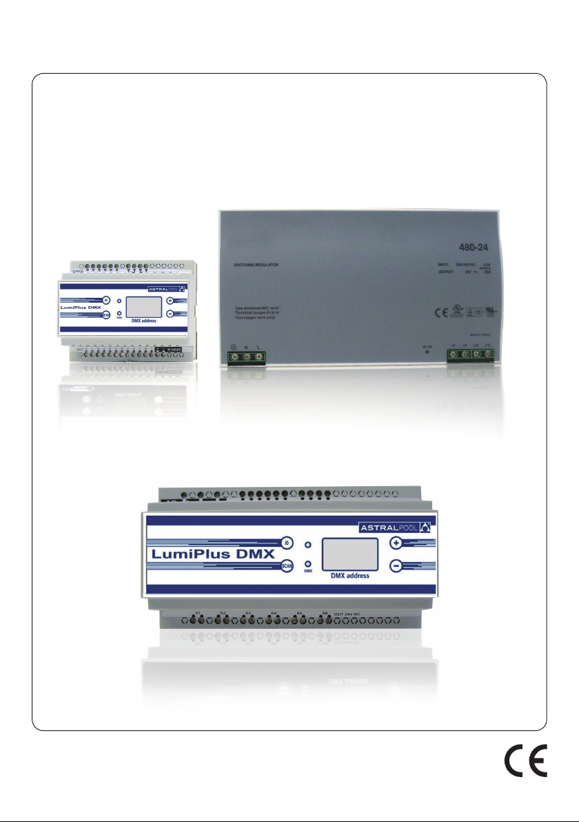
• ONLED DMX Power Supply:
I0832DMXI52: with power supply incorporated
I0832DMXFEI52: with external power supply
• Installation and maintenance manual.
• External Power Supply (only for power supply code I0832DMXFEI52, it works to 24VDC).
2. GENERAL FEATURES:
This product is exclusively designed to be used with Mini projectors, Quadraleds and Halospots of DMX RGB LEDs by Ig-
nialight. The manufacturer is not liable for possible damage or defects if products other than Ignialight products are used.
If the Power Supply does not receive DMX signal, the projectors will remain off.
This is an electrical device corresponding to class II, it is supplied to 230V; 50Hz.
3. GENERAL INSTALLATION:
Make sure that when installing the DMX Power Supply it is protected of corrosives environments.
The Power Supply I0832DMXFEI52 is connected to 24VDC by means of terminals 14 and 15. It can support up to a
maximum of 400VA. This power supply will be able to control up to a maximum of 100 Mini projectors RGB DMX of 4W
or 18 Halospot projectors RGB DMX of 21W.
Supply input (24 Vcc): + gConnection 14
- gConnection 15
Input /Output 1 DMX: GND gConnection 20
– gConnection 21
+ gConnection 22
Input /Output 2 DMX: GND gConnection 23
– gConnection 24
+ gConnection 25
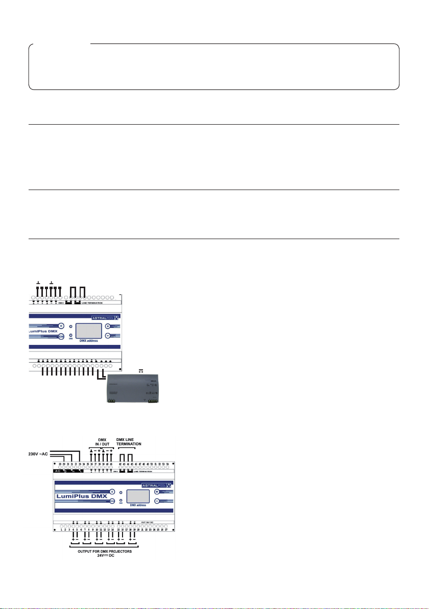
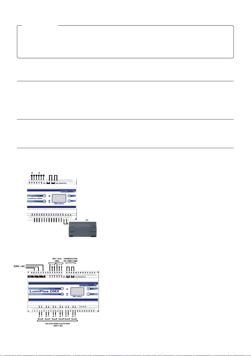
The Power Supply I0832DMXI52 is connected directly to the electrical red of 230V-AC through the borne 29, 31 and
33. It can support up to a maximum of 60VA, so 9 Mini projectors RGB DMX or 2 Halospots RGB DMX.
Supply Input (230V ~AC): GND gConnection 29
N gConnection 31
L gConnection 33
Input/ Output 1 DMX: GND gConnection 36
– gConnection 37
+ gConnection 38
Input/ Output 2 DMX: GND gConnection 39
– gConnection 40
In installations with long lengths of power lines, it is advisable to install
the Power Supplies as near of the projectors as possible (with a longer
230V-AC line).
DMX IN/OUT
DMX LINE
TERMINATION
- + - +
+ - + - + - + - + - + -
24V DC
OUTPUT FOR DMX PROJECTORS
3
4. OPERATION
The Power Supply receives orders from the DMX controller (for example the controllers IGNIALIGHT: OnDMX 66596 or
OnDMX PRO 66597) of the system by means of the DMX bus, and operates on the projectors connected. While the DMX
signal is not received from the controllers, the projectors will remain off.
This power supply has been designed for use only with DMX protocol and with controllable elements via DMX Ignialight
of 24V DC.
The DMX Power Supply DMX allows the connection up to a maximum of 9 RGB DMX projectors by independent chan-
nels. The Power Supply has 6 dotted outputs, therefore it does not matter to which of them the projectors are connected.
3 DMX channels can be controlled through this DMX Power Supply, corresponding to red, green and blue of each one
of the projectors connected to it. In this way, it is possible to achieve 256 different levels for each colour. By mixing these
three colours, over 16 million of colours can be obtained.
It is necessary that each power supply has an assigned address that will determine the channels it can control (see
Assignment of DMX address).
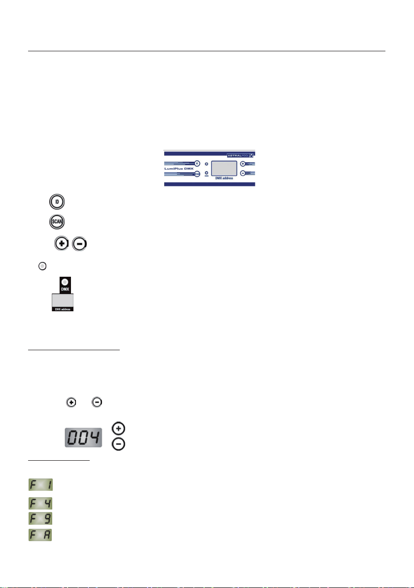
The module, for its functioning, has:
- 4 buttons
- 2 indicator leds
- One display
Button : It allows manage the projectors identication (in – out – save).
Button : It checks the connected projectors, for their identications or to check out their functioning.
Buttons : They are used to increase/decrease the projectors identication number or the DMX address of the
Power Supply, it depends of the functioning mode.
ID LED: It provide that the Power Supply is receiving and executing the dates transmitted by the DMX controller.
DMX LED : It shows that the Power supply is receiving and executing the data transmitted by the DMX.
Display : Depending on the functioning mode, it can indicate:
- Address of the DMX Power Supply.
- Functioning mode.
- Identication number of the projector.
Assignation of DMX address
Each DMX Power Supply receives a DMX signal and must have assigned a DMX base direction that will determine the
channels that it will be able to control.
The Power Supply, for each ID, uses 3 DMX channels: red, green and blue, the display of Power Supply shows the ad-
dress corresponding to the red color of rst ID, the following address corresponds to the green and the next one to the
blue. If for example in the display we have the “004” this indicates that through the channels 4,5 and 6 will be controlled
the red, green and blue color of the projectors group with ID 1 (See Projectors Identication).
The buttons and that are next to the display are used to select the DMX address. Once the wished address is
selected, its memorizing takes some seconds ( 3 seconds approx.). After that, the Power Supply will already be totally
operative.
Example:
Functioning Modes
This DMX Power Supply has 4 possible functioning modes, according to the number of RGB channels to use to the
connected projectors:
Only one RGB group (3 DMX channel)
4 RGB groups (12 DMX channels)
9 RGB groups (27 DMX channels)
For special applications.

4
F1 is the default functioning mode. To change the functioning mode, all buttons must be pressed together and
during some seconds, until the wished mode appears on the display: F1, F4 or F9 (The FA mode is used only for special
applications).
Projectors Identication
The DMX Power Supply allows the connection of up to maximum of 9 RGB DMX projectors with independent channels.
They can be connected all in the same output or in different ones.
All of the connected projectors can have a number ID assigned. The steps to identify the different projectors are as
follows:
1. Press button . to go to the ID mode. Then, ID LED is switched on, the ID number we are on is shown on the
display and the projectors identied with that ID are also switched on.
2. The selected ID increases/decreases pressing the buttons and consequently, are the projectors with the
selected ID get illuminated.
3. Select on of the projectors pressing the button several times, until the wished projector lights up intermittently.
4. Choose the ID to assign, pressing the and buttons.
5. Save the selection made, with a long pressure to the ID button. The ID LED is switched off.
DMX line termination
The DMX Power Supplies are serially connected along the DMX BUS.
Once they are connected, the last terminal of the DMX line must have activated the line termination. (On the other DMX
Power Supplies, the line termination cannot be activated).
For the model I0832DMXFEI52 the line termination is activated tapping the cable among the borne 27 and 28 and another
cable among the borne 29 and 30. For the model I0832DMXI52 is activated connecting the connections 42 and 43 with
a cable and connecting with another cable the connections 44 and 45.
DMX communications bus
The DMX signal can be affected by electrical interferences proceeding from other equipments. It is advisable to install the
DMX bus away from the electric cables and other interferences.
The maximum length of the DMX bus is around 100m, although it varies depending on the conditions of each installation.
In adverse conditions, such as longer lengths or line derivations, repeaters (splitters) should be installed.
The DMX signal is transmitted from equipment to equipment through a “daisy chain” type connection, where the equi-
pments are serially connected. The different equipments can be connected at any point of the line whatever is their
assigned address.
It cannot connect more than one DMX controller in the same DMX bus.
Only one type of cable can be used: twisted pair cable and shielded with a nominal impedance of 120 ohms (80-150) and
low capacitance, with a minimum thickness equivalent to 24 AWG (DMX cable).
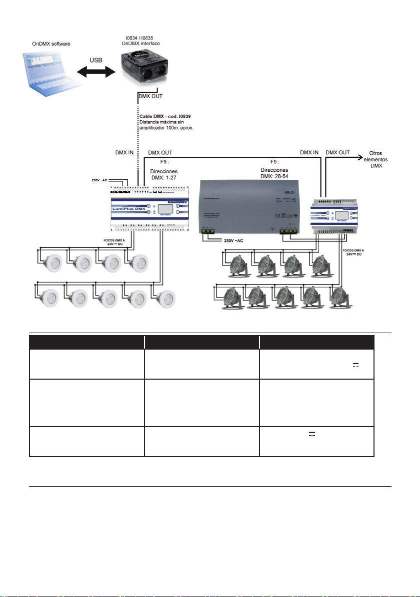
5. EXAMPLE OF A DMX SYSTEM
In a DMX system, there should be a controller and a power supply and different terminals can be used.
A system with the following elements is given in the connection diagram below:
- DMX controller: Ignialight DMX (code 66596), including software and interface.
- Terminals:
1x DMX Power Supply (code I0832DMXFEI52), on mode F9 with 9 Halospot projectors RGB DMX
1x DMX Power Supply (code I0832DMXI52), on mode F1 with 9 Mini LED projectors RGB DMX
The Ignialight DMX interface is connected to all the DMX terminals of the installation through a DMX cable (code I0839)
as shown in the gure.
5
6. TROUBLESHOOTING
Problems Usual causes Solutions
The display that indicates the DMX
address does not turn on
Current is not reaching the
equipment
Check the mains socket (230 V~ac
of power supply) and the 24V DC
power line
The green LED in the DMX
modulator does not light up
Defective DMX signal Check the installation of the DMX
line. Only the line termination of the
last DMX equipment of the DMX
communications bus should be
activated
The projectors change colour or
go out for a few moments
Faulty power supply in the
projectors or in the DMX
modulator
Check the 24V DC Power
supply line of the projectors and
the DMX modulator
If you are unable to solve the problem with these instructions, contact the technical department of IGNIALIGHT.
7. SAFETY WARNINGS
• The persons who are in charge of assembly should have the required qualications for this type of work.
• Avoid making contact with the electric voltage.
• Comply with the current standards regarding accident prevention.
• In this regard, the IEC 364-7-702 standards must be observed. WIRING IN BUILDINGS. SPECIAL WIRING. SWIM-
MING POOLS.
• Any operation related to the maintenance or replacement of parts should be performed with the oodlamp
disconnected from the electric power system.
• The manufacturer is not responsible in any circumstances for assembly, installation or start-up of any electric
components which have been inserted or handled at locations other than its own premises.
6
Para conseguir un óptimo rendimiento del Alimentador OnDMX V2, es conveniente observar las instrucciones
que se indican a continuación:
1. COMPRUEBE EL CONTENIDO DEL EMBALAJE:
El contenido de la caja es :
• Alimentador ONLED DMX:
I0832DMXI52 : con fuente de alimentación incorporada
I0832DMXFEI52 : con fuente de alimentación externa
• Manual de instalación y mantenimiento
• Fuente de alimentación externa (sólo para el alimentador I0832DMXFEI52, que funciona a 24VDC)
2. CARACTERÍSTICAS GENERALES:
Este producto está exclusivamente diseñado para utilizarse con proyectores Mini, Quadraleds y Halospots de LEDs
RGB DMX, el fabricante no se responsabiliza de posibles daños o desperfectos si no se utilizan productos IGNIALIGHT.
Si el Alimentador no recibe señal DMX los proyectores permanecerán apagados.
Se trata de un aparato eléctrico de clase II, se alimenta a 230V ; 50Hz.
3. INSTALACIÓN GENERAL:
Instale el alimentador DMX protegido de ambientes corrosivos.
El Alimentador I0832DMXFEI52 se conecta a 24VDC mediante los bornes 14 y 15. Puede soportar hasta un máxi-
mo de 400VA. Por tanto podría controlar un máximo de 100 proyectores Mini RGB DMX de 4W o bien 18 proyectores
halospot RGB DMX de 21W.
Entrada alimentación (24 Vcc): + gConexión 14
- gConexión 15
Entrada /Salida 1 DMX: GND gConexión 20
– gConexión 21
+ gConexión 22
Entrada /Salida 2 DMX: GND gConexión 23
– gConexión 24
+ gConexión 25
El Alimentador I0832DMXI52 se conecta directamente a la red eléctrica de 230V~AC mediante los bornes 29, 31 y
33. Puede soportar hasta un máximo de 60VA, por tanto 9 proyectores Mini RGB DMX o bién 2 halospots RGB DMX.
Entrada alimentación (230V ~AC): GND gConexión 29
N gConexión 31
L gConexión 33
Entrada /Salida 1 DMX: GND gConexión 36
– gConexión 37
+ gConexión 38
Entrada/Salida 2 DMX: GND gConexión 39
– gConexión 40
+ gConexión 41
IMPORTANTE: El manual de instrucciones que usted tiene en sus manos, contiene información fundamen-
tal acerca de las medidas de seguridad a adoptar a la hora de la instalación y la puesta en funcionamiento.
Por ello, es imprescindible que tanto el instalador como el usuario lean las instrucciones antes de pasar al
montaje y la puesta en marcha.
Conserve este manual para futuras consultas acerca del funcionamiento de este aparato.
ESPAÑOL
DMX IN/OUT
TERMINACIÓN
DE LÍNEA DMX
- + - +
+ - + - + - + - + - + -
24V DC
SALIDAS PARA FOCOS DMX

7
En una instalación con grandes longitudes de línea de alimentación, es aconsejable instalar los alimentadores lo más
cerca posible de los proyectores (alargando la linea de 230V~AC).
4. FUNCIONAMIENTO
El alimentador recibe las órdenes del controlador DMX (por ejemplo los controladores IGNIALIGHT OnDMX, 66596, o
OnDMX PRO, 66597) del sistema mediante el bus DMX y actúa sobre los proyectores que tenga conectados. Mientras
no reciba señal DMX de parte del controlador, los proyectores permanecerán apagados.
Este alimentador ha sido diseñado para ser usado únicamente con protocolo DMX y con los elementos controlables vía
DMX de IGNIALIGHT de 24V DC.
El Alimentador DMX permite conectar hasta un máximo de 9 proyectores RGB DMX con canales independientes. El
alimentador dispone de 6 salidas punteadas, de manera que es indiferente a cuál de ellas conectamos los proyectores.
Mediante este Alimentador DMX se pueden controlar 3 canales DMX que corresponderán a los colores rojo, verde y azul
de cada uno de los proyectores conectados a dicho Alimentador DMX. De este modo se pueden conseguir 256 niveles
distintos para cada color. Mezclando los tres colores se pueden obtener más de 16 millones de colores.
Cada alimentador debe tener asignada una dirección que le determinará los canales que podrá controlar (ver Asignación
de dirección DMX).
El módulo, para su funcionamiento, dispone de:
- 4 botones
- 2 LEDs indicadores
- un display
Botón : Permite manejar la identicación de los proyectores (entrar – salir – guardar).
Botón : Recorre los proyectores conectados, para su identicación o para comprobar su funcionamiento.
Botones : Se usan para aumentar/disminuir la identicación de los proyectores o la dirección DMX, según
el modo de funcionamiento en que estemos trabajando.
LED ID : Indica que el alimentador está trabajando en modo ID (identicación de proyectores).
LED DMX :Indica que el alimentador está recibiendo y ejecutando los datos que le transmite el controlador DMX.
Display : Según el modo en que estemos trabajando, puede indicar:
- la dirección del Alimentador DMX,
- el modo de funcionamiento
- el número del proyector.
Asignación de dirección DMX
Cada Alimentador DMX recibe una señal DMX y debe tener asignada una dirección DMX, que le determinará los canales
que podrá controlar.
El alimentador, para cada ID, utiliza 3 canales DMX: rojo, verde y azul, el display del alimentador muestra la dirección
correspondiente al color rojo del primer ID, la siguiente dirección corresponde al verde y la siguiente al azul. Si por ejem-
plo en el display tenemos el “004” esto indica que a través de los canales 4, 5 y 6 se controlaran los colores rojo, verde
y azul del grupo de proyectores con ID 1 (ver Identicación de proyectores).
Para seleccionar la dirección DMX se utilizan los botones y que están al lado del display. Una vez seleccionada la
dirección deseada, ésta tardará 3 segundos en memorizarse después de los cuales el alimentador ya estará totalmente
operativo.
Ejemplo:
Modos de funcionamiento
Este Alimentador DMX tiene 4 modos de funcionamiento posibles, según el número de canales RGB a utilizar para los
proyectores conectados:
un sólo grupo RGB (3 canales DMX)
4 grupos RGB (12 canales DMX)
9 grupos RGB (27 canales DMX)
para aplicaciones especiales

8
El modo de funcionamiento, por defecto, es F1. Para cambiar el modo de funcionamiento, se debe presionar conjunta-
mente ambos botones y , durante unos segundos y hasta que aparezca en pantalla el modo deseado: F1, F4 o
F9 (El modo FA sólo se utiliza para aplicaciones especiales).
Identicación de proyectores
El Alimentador DMX permite conectar hasta un máximo de 9 proyectores RGB DMX con canales independientes. Pue-
den estar conectados todos en la misma salida o en salidas diferentes.
Todos los proyectores conectados pueden tener asignada un número ID. Los pasos a seguir para la identicación de los
proyectores son los siguientes:
1. Entrar en modo ID, presionando el botón . Entonces, se ilumina el LED ID, en el display se muestra la ID en la
que nos encontramos y también se encienden los proyectores identicados con esa ID :
2. La ID seleccionada aumenta/disminuye presionando los botones y . En consecuencia, se ven iluminados los
proyectores que tienen la ID seleccionada.
3.Seleccionar el proyector deseado presionando varias veces el botón , hasta que el proyector deseado se ilumine
de forma intermitente.
4. Escoger la ID a asignar, presionando los botones y .
5. Guardar la selección hecha, mediante una pulsación larga del botón ID. Se apaga el LED ID.
Terminación de línea DMX
Los Alimentadores DMX se conectan en serie mediante el BUS DMX.
Una vez están conectados, el último equipo debe tener la terminación de línea activada. (La terminación de línea debe
estar desactivada en los demás equipos).
En el modelo I0832DMXFEI52 la terminación de línea se activa punteando un cable entre los bornes 27 y 28 y otro cable
entre los bornes 29 y 30. En el modelo I0832DMXI52 hay que poner un cable entre el 42 i 43 i otro cable uniendo 44 i 45.
Bus de comunicaciones DMX
La señal DMX se puede ver afectada por interferencias eléctricas procedentes de otros equipos. Es aconsejable instalar
el bus DMX separado de los cables de electricidad y otras posibles interferencias.
La máxima longitud del bus DMX está alrededor de los 100m, aunque varía en función de las condiciones de cada
instalación. Para condiciones adversas, tales como longitudes más grandes o derivaciones de línea, habrá que instalar
repetidores (splitter) .
La señal DMX se transmite de equipo a equipo a través de una conexión de tipo “daisy chain”, donde los equipos se
conectan en serie. Los diferentes equipos se pueden conectar en cualquier punto de la línea independientemente de la
dirección asignada.
No se puede conectar más de un controlador DMX en el mismo bus DMX.
Únicamente se utilizará cable de par trenzado y apantallado con impedancia nominal de 120 ohmios (80 – 150) y baja
capacitancia, con un grosor mínimo equivalente a 24 AWG (cable DMX).
5. EJEMPLO DE SISTEMA DMX:
En un sistema DMX tiene que haber un controlador y una fuente de alimentación y pueden intervenir distintos tipos de
terminales.
En el siguiente esquema de conexionado se muestra un sistema con los siguientes elementos:
- Controlador DMX: DMX (código 66596), incluye software e interfaz.
- Terminales:
1x Alimentador DMX (código I0832DMXFEI52), en modo F9 y con 9 proyectores halospot RGB DMX
1x Alimentador DMX (código I0832DMXI52), en modo F1 y con 9 proyectores mini LED RGB DMX
El interfaz IGNIALIGHT DMX se conecta a todos los terminales DMX de la instalación mediante un cable DMX (código
I0839) tal y como se puede observar en la imagen.

9
6. PROBLEMAS/ SOLUCIONES
Problemas Causas habituales Soluciones
El display que indica la dirección
DMX no se enciende.
No llega corriente al equipo Revise la toma de red (230V~AC de la
fuente de alimentación) y la línea de ali-
mentación de 24V DC
No se enciende el LED verde en el
modulador DMX
Señal DMX defectuosa Revise la instalación de la línea DMX.
Solamente el último equipo DMX del
bus de comunicaciones DMX tiene que
tener la terminación de línea activada
Los proyectores cambian de color
o se apagan por momentos
Alimentación defectuosa en los pro-
yectores o en el modulador DMX
Revise la línea de 24V
DC de
alimentación de los proyectores y el
modulador DMX
En caso que el problema no sea resuelto con alguna de estas medidas póngase en contacto con el departamen-
to técnico de IGNIALIGHT.
7. ADVERTENCIAS DE SEGURIDAD:
• Las personas que se encarguen del montaje deben poseer la calicación requerida para este tipo de trabajos.
• Se debe evitar entrar en contacto con la tensión eléctrica.
• Se deben respetar las normas vigentes para la prevención de accidentes.
• A tal respecto, se deben cumplir las normas IEC 364-7-702: INSTALACIONES ELÉCTRICAS EN EDIFICIOS.
INSTALACIONES ESPECIALES PISCINAS.
• Cualquier operación de mantenimiento debe realizarse con el proyector desconectado de la red.
• El fabricante en ningún caso se responsabiliza del montaje, instalación o puesta en funcionamiento de cual-
quier manipulación o incorporación de componentes eléctricos que no se hayan llevado a cabo en sus insta-
laciones.

10
SACOPA, S.A.U.
GB PRODUCTS:
E PRODUCTOS:
DECLARATION CE OF CONFORMITY
The products listed above are in compliance with:
· Electromagnetic Compatibility Directive 2004/108/EEC.
· Low Voltage Directive 2006/95/EEC.
· European Standard EN 60598-1.
DECLARACION CE DE CONFORMIDAD
Los productos arriba enumerados se hallan conformes con:
· Directiva de compatibilidad electromagnética 2004/108/CEE.
·
Directiva de equipos de baja tensión 2006/95/CEE.
· Normativa Europea EN 60598-1.
Signature / Qualication:
Firma / Cargo:
SACOPA, S.A.U.
Pol. Ind. Poliger Sud –
Sector I
17854 SANT JAUME DE
LLIERCA
SPAIN
St. Jaume de Llierca,
March of 2011
Gerent
I0832DMXI52 / I0832DMXFEI52

11

I0832E204I52
Rev02
I0832DMXFEI52
• We reserve to change all or part of the articles or contents of this document, without prior notice.
• Nos reservamos el derecho de cambiar total o parcialmente las características de nuestros artículos o contenido de este documento
sin previo aviso.
Made in Spain
Sacopa, S.A.U.
Pol. Ind. Poliger Sud – Sector I
17854 Sant Jaume de Llierca (Spain)
I0832DMXI52
This manual suits for next models
1
Table of contents
Languages:
Other Astral Pool Power Supply manuals


Popular Power Supply manuals by other brands

Allied Telesis
Allied Telesis AT-WDRPS-10 installation guide

Sharkoon
Sharkoon SilentStorm Icewind 550 manual

Siemens
Siemens 4AV2306-2EB00-0A operating instructions

Altronix
Altronix ALTV1224DC installation instructions

Delta Electronics
Delta Electronics 1-phase 35W Brochure & specs

GW Instek
GW Instek GPS-2303 user manual


