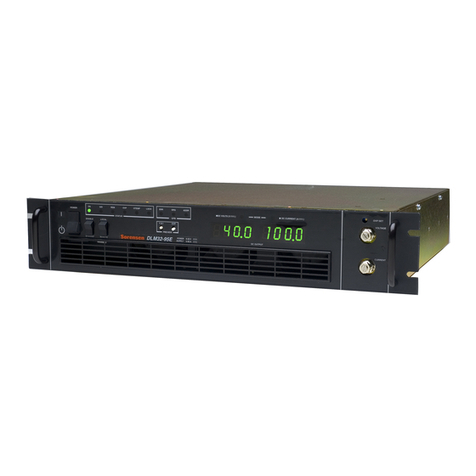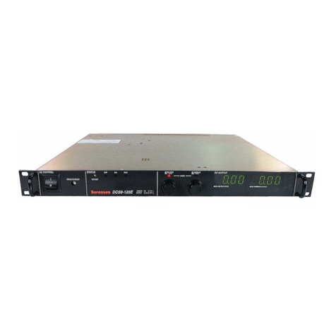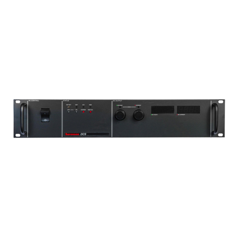
LM 600W Series
M362161-01 Rev L xvii
LIST OF FIGURES
Figure 2-1. LM 600W Series Outline rawing ............................................... 2-2
Figure 2-2. Rackmount Kit (Single Unit Option) ............................................... 2-5
Figure 2-3. Rackmount Kit ( ual Unit Option) .................................................. 2-7
Figure 2-4. Remote Sense Connector ............................................................ 2-12
Figure 2-5. Single Load Connection with Local Sensing ................................... 2-14
Figure 2-6. Single Load Connection with Remote Sensing ............................ 2-14
Figure 2-7. Multiple Load Connection with Local Sensing ................................ 2-15
Figure 2-8. istribution Bus Connection with Remote Sensing ...................... 2-16
Figure 2-9. Parallel Connection of Units with Remote Sensing ......................... 2-17
Figure 2-10. Parallel I/O Connector ................................................................. 2-18
Figure 2-11. Series Connection of Units with Local Sensing ........................... 2-20
Figure 2-12. Series Connection of Units with Remote Sensing ...................... 2-21
Figure 2-13. iode Selection .......................................................................... 2-22
Figure 3-1. Front and Rear Panel Views .......................................................... 3-2
Figure 3-2. CV and CC Modes of Operation .................................................... 3-6
Figure 4-1. SETUP Switch ............................................................................... 4-1
Figure 4-2. Remote Analog Interface Connector .............................................. 4-3
Figure 4-3. Voltage–Source Programming of Output Voltage .......................... 4-8
Figure 4-4. Voltage–Source Programming of Output Current .......................... 4-9
Figure 4-5. Voltage–Source Programming of OVP ........................................ 4-10
Figure 4-6. Resistance Programming of Output Voltage ................................ 4-11
Figure 4-7. Resistance Programming of Output Current ................................ 4-12
Figure 4-8. Resistance Programming of OVP ................................................ 4-13
Figure 4-9. EXTERNAL–OFF with Voltage Source ........................................ 4-14
Figure 4-10. EXTERNAL–OFF with AUXILIARY 5 V C OUTPUT ................... 4-15
Figure 5-1. Main PWA Location of Test Points and Potentiometers ................. 5-4
Figure 5-2. isplay PWA Location of Potentiometers ....................................... 5-4
LIST OF TABLES
Table 1–1. LM Series Specifications .............................................................. 1-4
Table 2–1. LM 600W Rackmount Kit Parts List ............................................. 2-3
Table 2–2. Wire ata ..................................................................................... 2-10
Table 2–3. Remote Sense (REM SNS) Connector Pinout ............................. 2-13
Table 2–4. Parallel I/O Connector Pinout ....................................................... 2-19
Table 4–1. Setup Switch Functions .................................................................. 4-2
Table 4–2. Remote Analog Interface Connector Pinout ................................... 4-3
Table 4–3. Remote Programming Options ....................................................... 4-7
Table 4–4. Remote Monitoring ....................................................................... 4-15
Table 4–5. Remote igital Status Signals ........................................................ 4-16
Table 5–1. Troubleshooting Guide ................................................................... 5-2
Table 5–2. Internal Fuses ................................................................................. 5-3


