5
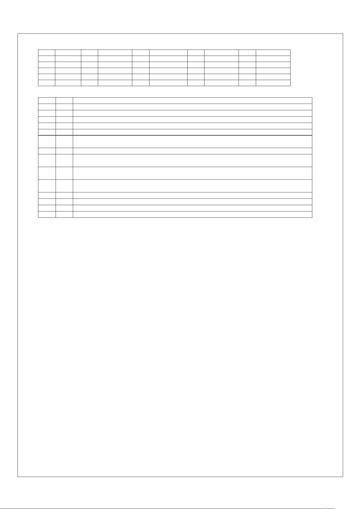
Connector Pin No. Assignment(CN500) : D-Type Right Angle 25 positions
Pin No. Pin No. Pin No. Pin No. Pin No.
2
1
3
4
5
Assignment Assignment Assignment Assignment Assignment
AC-OK-A
ON/OFF-A
DC-OK-A
V-TRIM-A
T-ALARM-A
7
13
9
8
10
14
15
6
12
11 16
17
23
21
22
25
18
19
20
24
AC-OK-B
DC-OK-B
ON/OFF-B
+5V-AUX
GND-AUX
NC
CS
ON/OFF-C
V-TRIM-B
T-ALARM-B
AC-OK-C
DC-OK-C
SCL
-S
+V
-V
V-TRIM-C
T-ALARM-C
+S
SDA
Pin No. Function Description
1,8,15
2,9,16
3,10,17
4,11,18
5,12,19
7
23
25
14
6
ON/OFF
AC-OK
DC-OK
V-TRIM
T-ALARM
GND-AUX
SCL
-V
CS
+5V-AUX
Each unit can separately turn the output on and off by electrical or dry contact between ON/OFF A,B,C(pin 1,8,15) and -S(pin 21). Short: ON, Open:OFF.
High : When the input voltage is ≧82Vrms +/-4V. Low : when the input voltage in≦82Vrms +/-4V.
High : When the Vout≧80%+/-5%. Low : When Vout ≦80%+/-5%
Connection for output voltage trimming. The voltage can be trimmed within its defined range.
High : When the internal temperature is within safe limit. Low : 10℃ below the thermal shut down limit.
Auxiliary voltage output GND. The signal return is isolated from the output terminals (+V & -V).
2
Serial clock used on RCP-1000-C models. Refer to the I C interface description.
Negative output voltage. For local sense use only, can't be connected directly to the load.
Current sharing signal. When units are connected in parallel, the CS pins of the units should be connected to allow current balance
between units.
Auxiliary voltage output, 4.3~5.3V, referenced to GND-AUX(pin 7). The maximum load current is 0.3A. This output has the built-in
"Oring diodes" and is not controlled by the remote ON/OFF control.
20
21
+S
-S
Positive sensing. The +S signal should be connected to the positive terminal of the load. The +S and -S leads should be twisted in pair to
minimize noise pick-up effect. The maximum line drop compensation is 0.5V.
Negative sensing. The -S signal should be connected to the negative terminal of the load. The -S and +S leads should be twisted in pair to
minimize noise pick-up effect. The maximum line drop compensation is 0.5V.
22 +V Positive output voltage. For local sense use only, can't be connected directly to the load.
24 SDA 2
Serial data used on the RCP-1000-C models. Refer to the I C interface description.
3.Functions
3.1 Input Voltage Range
3.2 Inrush Current Limiting
3.3 Output Power
3.4 Power Factor Correction (PFC)
3.5 Output Voltage Adjustment
◎ Nominal input voltage range is AC 90~264V or DC 127~370V.
◎To insure proper operation, AC input should be within the pre-specified range. The wrong input will cause the power supply to
operate improperly, lose the PFC function or even be damaged.
operating at lower input voltage (<100VAC).
◎Since the RCP Series have built-in active PFC circuit, there will be lower efficiency and output derating is required when
◎Built-in inrush current limiting circuit.
◎ Single Unit
◎Built-in active power factor correction (PFC) function. Under full load output and the input voltage is within the range of
3.5.1 Adjustment of single unit
3.5.2 Adjustment of single unit or the whole rack system
90~230Vac, PF>0.96; if the output is less than full load or the input voltage is higher than 230Vac, the PF value will be
a little less than 0.96.
Output voltage of one RCP-1000 is adjustable through the potentiometer (SVR51, can be found under the small circular
hole on top of the unit). Please use a cross-screwdriver with isolated holder to make the adjustment.
◎ Output voltage difference of each unit in the same rack should be maintained within ±1%, or the effectiveness of current
sharing might be influenced.
◎ Output voltage can be adjusted between 90%~110% of rated value by adding external resistors (R1 and R2). Please refer
to Figure 3-1for details.
◎ When the output is tuned to a higher voltage, please notice that the load current should be decreased accordingly. The
output wattage of each unit should not exceed its rated value under any circumstances.
◎ Whole System
RCP-1000-12 : 720W (12V / 60A)
RCP-3K1U□-12 : 2160W (12V / 180A)
RCP-3K1U□-24 : 2880W (24V / 120A)
RCP-3K1U□-48 : 3024W (48V / 63A)
RCP-1000-24 : 960W (24V / 40A)
RCP-1000-48 : 1008W (48V / 21A)
◎The external switch, if needed, should have a current rating exceeding the maximum inrush current.
◎Since the inrush current limiting circuit mainly consists of thermistor and relay, after turning off the power supply, a 10 second cool
down period is recommended before turning it back on. Inrush current will be much higher than the specified value if input thermistor
is not allowed sufficient time to cool down.
◎ Description of CN500 in/out connection pins


