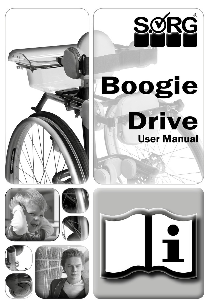
SORG Boogie Drive Service manual

Service Record
1
Boogie
Drive
Service Record

Boogie Drive
2
IMPRINT
SORG Rollstuhltechnik GmbH+Co.KG
Benzstraße 3-5
D-68794 Oberhausen-Rheinhausen
Germany
Tel. +49 7254-9279-0
Fax +49 7254-9279-10
E-mail info@sorgrollstuhltechnik.de
Web www.sorgrollstuhltechnik.de
REVISION STATUS
Revision: 2018-09-25
TECHNICAL STATUS
Technical changes and misprints reserved. The pictures in
this user manual can – depending on the individual equip-
ment – differ from the actual equipment components. How-
ever, a corresponding conduction is possible.
REHAKIND
We are a member of rehaKIND e.V.
International association
child and adolescent rehabilitation
COPYRIGHT
© by SORG Rollstuhltechnik GmbH + Co. KG Benzstraße
3-5, 68794 Oberhausen-Rheinhausen.
All texts and pictures in this user manual underlie the
international copyright protection and are not allowed to be
published without our consent – not even in excerpts!
CERTIFICATION
Our Quality Management System is certi ied according
to the ISO 9001:2015 under the certi icate no. 12 100
20070 TMS.

Service Record
3
TABLE OF CONTENT
IMPRINT 2
REVISION STATUS 2
TECHNICAL STATUS 2
REHAKIND 2
COPYRIGHT 2
CERTIFICATION 2
OVERVIEW MOBILE STANDING DEVICE 4
1 PREAMBLE 5
1.1 GENERAL INFORMATION 5
1.2 SIGN EXPLANATION 5
1.3 RECEPTION 5
1.4 SERVICE AND MAINTENANCE 5
1.5 DOCUMENTATION 6
1.6 BASICS TO ALL ADJUSTMENT WORK
ON THE MOBILE STANDING DEVICE 6
1.7 TIGHTENING TORQUE
AND TOOLS 6
1.8 GENERAL SAFETY INSTRUCTIONS 7
1.9 LOADING AND TRANSPORTING 7
2 ADJUSTMENTS 8
2.1 ASSEMBLY GROUP WHEELS 8
2.1.1 Wheel position 8
2.1.2 Camber 9
2.1.3 Sprung back casters 10
2.2 ASSEMBLY GROUP CENTRE COLUMN11
2.2.1 Height adjustment of the centre column
with frame size 1 11
2.2.2 Setting the angle of the centre column
by telescope and clamp lever 11
2.2.3 Angle adjustment of the centre column
by gas pressure spring 11
2.3 ASSEMBLY GROUP STANDARD
FOOT PLATES 12
2.3.1 Setting the height of the foot plate
holder 12
2.3.2 Positioning the standard foot plates 12
2.3.3 Abducting the standard foot plates 12
2.3.4 Turning the standard foot plates
horizontally
12
2.4 ASSEMBLY GROUP 3D FOOT PLATES
WITH ANGLE ADJUSTMENT 13
2.4.1 Setting the angle of the 3D foot plates 13
2.4.2 Abducting the 3D foot plates 13
2.4.3 Setting the height of the 3D foot plates 13
2.4.4 Setting the depth of the 3D foot plates 13
2.5 FOOT SHELLS 13
2.6 ASSEMBLY GROUP CHEST
TRUSS PAD 14
2.6.1 Height of the chest truss pad 14
2.6.2
Angle of the chest truss pad 14
2.6.3
Side chest truss pad 14
2.7 ASSEMBLY GROUP PELVIC TRUSS
PADS 15
2.7.1 Adjusting the height 15
2.7.2 Adjusting the width 15
2.7.3 Adjusting the depth 15
2.8 ASSEMBLY GROUP POSTERIOR
TRUSS PAD PLUGGABLE 16
2.8.1 Crotch cushion 16
2.8.2 Posterior cushion 16
2.8.3 Side posterior truss pads 16
2.8.4
Back truss pads 16
2.9 ASSEMBLY GROUP POSTERIOR
TRUSS PAD WITH CRANK AND
SWIVEL BRACKET 17
2.9.1 Adjusting the height 17
2.9.2 Adjusting the depth 17
2.9.3 Adjusting the width 17
2.10 ASSEMBLY GROUP STANDARD
KNEE TRUSS PADS 18
2.10.1 Adjusting the truss pad width size 1 18
2.10.2 Adjusting the truss pad width size 2 18
2.10.3 Adjusting the height 18
2.10.4 Adjusting the depth 18
2.10.5 Adjusting the distance 18
2.11 ASSEMBLY GROUP KNEE TRUSS
PADS WITH RESTING BRACKETS 19
2.11.1 Adjusting the truss pad width 19
2.11.2 Adjusting the shear angle 19
2.11.3 Adjusting the height 19
2.11.4 Adjusting the depth 19
2.11.5 Adjusting the distance 19
2.12 ASSEMBLY GROUP THERAPY TABLE 20
2.12.1 Standard mounting 20
2.12.2 Mounting on the chest truss pad holder 20
2.13 ASSEMBLY GROUP FRAME 21
2.13.1 Frame size 1 and 2 (gas pressure spring
or telescope) 21
2.13.2 Frame size 3 (gas pressure spring) 21
2.13.3 Frame size 3 (telescope) 21
2.14 ASSEMBLY GROUP BELTS 21
3 TECHNICAL DATA 22
3.1 MEASURMENTS AND DIMENSIONS 22
3.2 MEANING OF LABELS 23
3.3 DECLARATION OF CONFORMITY 23
3.4 RETAILER VERIFICATION 24

Boogie Drive
4
1
2
3
4
5
6
7
8
OVERVIEW MOBILE STANDING DEVICE
1. chest truss pad
2. side chest truss pad
3. belt for side chest truss pad
4. cushion for posterior truss pad
with swivel bracket and crank
5. swivel bracket
6. sid posterior truss pad
7. centre column
8. standard knee truss pad
9. sprung back caster
10. standard foot plate
11. drum brake hub
12. gas pressure spring
13. front caster
14. release pedal for gas
pressure spring
1. chest truss pad
2. therapy table
3. toy box
4. crank for posterior truss
pad with swivel bracketl
5. side posterior truss pad
6. centre column
7. frame
8. drum brake hub
9. profiel wheel
10. built in handrim
11. side chest truss pad
12. belt for chest truss pad
13. star knob lock for the pelvic
truss pad with crank and
swivel bracket
14. swivel bracket
15. cushion for posterior truss
pad
16. axle plate
17. standard knee truss pad
18. standard foot plates
19. clamping device for the
height adjustment of the
back casters
20. locking lever for the back
casters
21. sprung back casters
1
2
3
4
5
6
7
8
9
9
10
1011121314
21
20
19
18
17
16
15
14
13
12
11

Service Record
5
1 PREAMBLE
1.1 GENERAL INFORMATION
�INDICATION
This service record contains directions for adjusting
the mobile standing device according to the individual
specifications of the user and is for your rehab technician
or therapist.
ATTENTION
For safety reasons, have all work done by your qualified
rehab technician.
Our mobile standing devices fulfil the guidelines and
regulations according to 93/42/EWG. Furthermore,
SORG Rollstuhltechnik is certified according to the Quality
Management System ISO 9001. With this, the quality of our
wheelchairs is ensured and documented from development
to assembly in each step.
If you have any questions our competent team will be glad
to assist you (+49 7254 9279.0).
1.2 SIGN EXPLANATION
ATTENTION
This is how individual-related safety aspects of utmost
importance are indicated.
�INDICATION
This is how possible indications of utmost importance are
labelled.
INFORMATION
This is how INFORMATION on mounting and adjustment
work is labelled.
READ
This refers to other chapters within the brochure or to
additional material.
BOLD PRINT
Text in bold print highlights important passages or remarks.
1.3 RECEPTION
DELIVERY
All of our wheelchairs/mobile standing devices are
mounted, tested for functionality and correctness in our
works and packaged into special cardboard boxes on
palettes by our shipping experts.
FORWARDING COMPANY
Receiving
�INDICATION
For liability reasons you must check the wheelchair/
mobile standing device IMMEDIATELY after receiving
it and IN THE PRESENCE of the deliverer (forwarding
company) for possible damages that may have occurred
during transportation.
CONFIRMATION OF RECEIPT
�INDICATION
Only sign the confirmation receipt after you have tho-
roughly checked the wheelchair for defects.
TRANSPORTATION DAMAGES
In case of damages, please proceed as follows:
• write a short record of the damage and review of
events, if possible include pictures clearly showing
the damage,
• have the bearer sign this damage report,
• get the personal information of the bearer (ID,
driver‘s license etc., or note the car number and
the delivering company)
• and inform us immediately.
�INDICATION
In case of damages, note on the confirmation receipt
that you have received the mobile standing device with
damages.
�INDICATION
According to valid law, damages reported late can
neither be asserted to us nor to the forwarding company!
1.4 SERVICE AND MAINTENANCE
�INDICATION
According to § 33 subparagraph 1, clause 4, [German]
SGB V, the responsibility of maintenance, repairs and
replacement lies with the benefactor. After agreement
with the benefactor, the user must have all safety relevant
inspections, maintenance work and if necessary repairs
conducted in order to make the wheelchair functional.
Explain these responsibilities and the procedure to the
user.
ATTENTION
Only regular maintenance of all safety relevent parts
on the mobile standing device by a qualified rehab
workshop protects you from damages and preserves our
mamanufacturer‘s warranty.

Boogie Drive
6
ATTENTION
Only original parts are to be used for all service and
maintenance work.
ATTENTION
With all work on movable and/or rotating parts there is a
RISK of BRUISING fingers and other body parts.
INFORMATION
Proceed according to the maintenance plan in the user
manual.
1.5 DOCUMENTATION
�INDICATION
Keep this service record in a safe place. All work/repairs
are to be documented in this service record.
�INDICATION
When returning the mobile standing device to the bene-
factor be sure to give this service record and the user ma-
nual as well. In the event of reuse, this service record is
an important source of information for your benefactor.It
provides evidence of regular inspections which might be
relevant in the event of warranty claim.
1.6 BASICS TO ALL ADJUSTMENT
WORK ON THE MOBILE STANDING
DEVICE
ATTENTION
BEFORE THE FIRST USE OF THE MOBILE STANDING
DEVICE THE CENTRE COLUMN, THE WHEELS, THE FOOT
PLATES, THE KNEE, POSTERIOR AND THE CHEST TRUSS
PADS MUST BE SET TO THE INDIVIDUAL MEASUREMENTS
OF THE USER. IT MUST BE CLOSE TO BEING READY FOR
USE.
IT IS NOT ADMISSIBLE TO MAKE ADJUSTMENTS WHEN
THE USER IS IN THE WHEELCHAIR! THEN, ONLY FINE
ADJUSTMENTS ARE ALLOWED TO BE MADE
.
ATTENTION
THE MOBILE STANDING DEVICE MUST BE EMPTY WHEN
ADJUSTING THE ANGLE OF THE CENTRE COLUMN WITH
TELESCOPE AND CLAMP LEVER.
INFORMATION
If the mobile standing device is used in an area without
threshold, it is recommended to set the back casters so
that each wheel has contact with the ground.
If you need to overcome doorways or the like more
frequently, it is recommended to set the back casters so
that the front casters are not touching the ground.
These adjustments are made by the height adjustment of
the back casters (see corresponding chapter).
ATTENTION
All parts of the mobile standing device are to be handled
with care. Removable parts are not to be thrown or
dropped!
ATTENTION
Before repairs or ajdustments are made, clean/disinfect
the mobile standing device and secure it from tipping
over and/or falling down.
ATTENTION
Only use original spare parts.
ATTENTION
Safety nuts are only to be used once. After first removal
the safety nut must be replaced by a new one.
1.7 TIGHTENING TORQUE AND TOOLS
INFORMATION
Technical changes reserved.
Screws
• M5: 5 Nm;
• M6: 7 Nm;
• M6 (axle plate) 10 Nm
• M8: 20 Nm;
• M10 (nut): 25 Nm; (caster)
• Fitting for quick-release axle: 35 Nm
Tools needed:
• Torque wrench (5-50 Nm)
• open-end wrench
• flex ratchet handle with socket wrench inserts
• hexagon screwdriver
• Phillips screwdriver
• flat head screwdriver
• plastic mallet
• side cutter
• threadlocker fluid
• bicycle inner tube repair kit
• work bench/jaw vise with rubber pads
Word explanation:
Loosen screw:
means to only loosen the screw so that the parts are still
held together but (e.g.)can be moved around along a slotted
hole.
Remove screw:
means to completely remove the screw from where it was
attached so that the parts are no longer connected.

Service Record
7
1.8 GENERAL SAFETY INSTRUCTIONS
ATTENTION
The references to possible risks that occur form the
use of the wheelchair/mobile standing device and are
directed to the user, are in the user manual. If necessary,
the user manuals can be downloaded from:
www.sorgrollstuhltechnik.de.
ATTENTION
BEFORE THE FIRST USE OF THE MOBILE STANDING
DEVICE, THE CENTRE COLUMN, THE WHEELS, THE FOOT
PLATES, THE KNEE, POSTERIOR AND CHEST TRUSS PADS
MUST BE SET TO THE INDIVIDUAL MEASUREMENTS OF
THE USER. IT MUST BE CLOSE TO BEING READY FOR USE.
IT IS NOT ADMISSIBLE TO MAKE ADJUSTMENTS WHEN
THE USER IS IN THE WHEELCHAIR! THEN, ONLY FINE
ADJUSTMENTS ARE ALLOWED TO BE MADE
.
ATTENTION
TO ADJUST THE ANGLE OF THE CENTRE COLUMN WITH
TELESCOPE AND CLAMP LEVER THE MOBILE STANDING
DEVICE MUST BE EMPTY.
ATTENTION
THE MOBILE STANDING DEVICE CAN ONLY BE USED
INDOORS ON A FLAT, FIRM SURFACE AND CAN ONLY BE
USED BY THE PERSON FOR WHOM IT WAS BUILT FOR
AND ADJUSTED TO
.
ATTENTION
On all rotating and turnable parts there is a risk of
bruising. This also goes for adjustment work and repairs.
ATTENTION: DANGER OF BRUISING
When operating the adjustable parts as well as fixation
and reparation work, there is an injury risk or risk of
crushing body parts in the pivoting range.
ATTENTION
The mobile standing device can only be used according
to its purpose (see user manual). Any other use or misuse
can contain serious risks for you and your surroundings.
Also, the guarantee or product liability can be terminated
in case of misuse!
ATTENTION
All building alterations are not to be done without our
approval and must be carried out and documented by us
or a qualified rehab technician.
READ
Consider the indications for maintenance and inspection at
the end of the operating instructions.
1.9 LOADING AND TRANSPORTING
ATTENTION
WHEN LOADING AND TRANSPORTING THE MOBILE
STANDING DEVICE IN A VEHICLE ALL DEMOUNTED/
LOOSE PARTS OF IT MUST BE STOWED AND TIED UP
SECURELY SO THAT IF A SUDDEN STOP OCCURS, THE
PARTS WIL NOT HARM ANYONE.
SECURE THE MOBILE STANDING DEVICE AND ALL LOOSE
PARTS WITH TENSION BELTS IN THE VEHICLE.

Boogie Drive
8
(A) (B)
2 ADJUSTMENTS
2.1 ASSEMBLY GROUP WHEELS
2.1.1 Wheel position
The chart below shows which distances and dimensions
with which body height and with which driving wheel are
possible.
The chart on the next page (page 9) explains, where
the quick release axle fittings and the axle plate need to
be mounted when the wheel size and/or the camber is
changed.
(1) With the horizontal change of the wheel position along
the hole rows 1, 2 or 3 you change the gripping distance
and the centre of gravity.
ATTENTION
A verticle adjustment of the wheel position is only
possible when the wheel size is changes at the same
time.
(2) To change the wheel position remove the driving wheels
and secure the mobile standing device from rolling away with
the wheel locks of the back casters:
• Remove the quick release axle fitting (A) on both
sides incl. the drum brake counterholder (B),
• place the fittings (A) in the desired new position
(see chart p.9) and retighten it.
• Proceed with the counterholder (B) in the same
manner.
• Make sure that the fittings (A) are mounted symet-
rical on both sides.
Frame size Size 1 Size 2
Body height
80-110 cm 100-130 cm
A Wheel size
24"x1"
ø58 cm
26"x1"
ø63 cm
28"x1"
ø68 cm
28"x1"
ø68 cm
30"x1"
ø75 cm
32"x1"
ø80 cm
Recomended at
elbow height
47 cm 52 cm 57 cm 57 cm 64 cm 69 cm
B Foot plate to top
handrim
39-47 cm 44-52 cm 49-57 cm 49-57 cm 56-64 cm 61-69 cm
C Upper
distance
between
the wheels
with
camber:
0°
not possible not possible not possible not possible not possible not possible
3°
44 cm 44 cm 43 cm 55 cm 54 cm 54 cm
6°
42 cm 41 cm 40 cm 52 cm 50 cm 50 cm
9°
40 cm 38 cm 37 cm 49 cm 47 cm 46 cm
12°
37 cm 35 cm 33 cm 46 cm 44 cm 42 cm
Frame size Size 3
Body height
120-150 cm
A Wheel size
32"x1"
ø80 cm
36"x1"
ø90 cm
Recomended at
elbow height
71 cm 81 cm
B Foot plate to top
handrim
61-69 cm 71-79 cm
C Upper
distance
between the
wheels with
camber:
0°
58 cm 58 cm
3°
55 cm 54 cm
6°
51 cm 49 cm
9°
48 cm 45 cm
12°
not possible not possible
(1)
(2)
1
2
3

Service Record
9
3°
6°
9°
12°
C
2.1.2 Camber
We mount the wheels according to your specifications to
the desired camber. With the camber you can change the
distance at the top between the driving wheels (for the
possible measurements see chapter 2.1.1).
Picture 1 shows each row (1-3) of the quick release axle for
the appropriate wheel size (see chart below) as well as the
appropriate attachment (A, B, C, D) of the axle plate in the
axle plate holder.
Picture 2 shows the bore picture for the possible camber
setting for frame size 1 and 2,
Picture 3 shows the bore picture for the possible camber
setting for frame size 3 and 4.
(4) To change the camber remove the driving wheels and
secure the mobile standing device from rolling away with
the wheel locks of the back casters.
• Remove on both sides both screws (A).
• Remove on both sides both screws (B).
• Move the axle plate (C) in the axle plate holder (D)
corresponding to the details on the basis of the
chart below.
• Replace all of the screws and tighten them and re-
place the wheels.
Frame size 1 Frame size 2
wheel size camber position wheel size camber position
24"
3° 3A
28"
3° 3B
6° 3A 6° 3C
9° 3B 9° 3C
12° 3C 12° 3D
26"
3° 2A
30"
3° 2A
6° 2A 6° 2A
9° 2B 9° 2B
12° 2C 12° 2C
28"
3° 1A
32"
3° 1A
6° 1A 6° 1A
9° 1B 9° 1B
12° 1C 12° 1C
Frame size 3
wheel size camber position
32"
0° 3A
3° 3A
6° 3B
9° 3C
36"
0° 1A
3° 1A
6° 1B
9° 1C
1
A
B
D2
3
(1)
(2)
(A)
(B)
(C)
(D)
(3)
(4)
0°
3°
6°
9°

Boogie Drive
10
2.1.3 Sprung back casters
If the mobile standing device is used in an area without
thresholds, it is recommended to set the wheels so that
each wheel has contact with the ground.
If you need to overcome doorways or the like more
frequently, it is recommended to set the back casters so
that the front casters are not touching the ground. These
adjustments are made by the height adjustment of the
back casters
(1+2) The height of the back casters is set as follows:
• Place the mobile standing device on an even
surface and secure it from rolling away by locking
the drum brake
.
• Loosen, on both sides, the screw (A) of the clamp (B)
on the back caster wheels,
• pull the steering gear case (C) as far out of the clamp
(B) or push it in as far until the desired height is
reached.
• First tighten the screw
(A) on one side.
• Adjust the steering gear case on the other side
according to this adjustment.
• Proceed as just described
• and also retighten the screws
(A)
there.
INFORMATION
On the steering gear case (C) there are grooves (D)
at a distance of 5 mm with which you can control the
evenness on both sides.
(A)
(D)
(A)
(B)
(B)
(2)
(1)
(C)
(C)
Steering gear case mounted short.
Steering gear case mounted long.

Service Record
11
2.2 ASSEMBLY GROUP CENTRE
COLUMN
The centre column can be set and adjusted in angle and
with frame size 1 it can also be adjusted in height.
2.2.1 Height adjustment of the centre column
with frame size 1
Should it become necessary to move the centre column
down:
• (1) Secure the mobile standing device from rolling
away by operating the drum brakes and with the
wheel locks of the back casters.
• Remove the driving wheels and, for better hand-
ling, all truss pads.
• Remove both screws (A) and spacer bushings on
the centre column (B).
• Move the centre column (B) one drilled hole down.
• Replace the screws (A) and the spacer bushings
• and retighten them.
2.2.2 Setting the angle of the centre column
by telescope and clamp lever
ATTENTION
THE ANGLE SETTING OF THE CENTRE COLUMN WITH TE-
LESCOPE AND CLAMP LEVER CAN ONLY TAKE PLACE
WHEN NOBODY IS IN THE MOBILE STANDING DEVICE.
(2) To change the angle:
• Secure the mobile standing device from rolling
away by operating the drum brakes and with the
wheel locks of the back casters.
• Loosen the clamp lever (A) of the telescope (B),
• place the centre column (C) in the desired position,
• close the clamp lever (A) tightly.
2.2.3 Angle adjustment of the centre column
by gas pressure spring
For frequent angle adjustment of the the centre column
(e.g. for alternating load) it is recommended to adjust the
angle with a gas pressure spring.
(3) To change the angle:
• Secure the mobile standing device from rolling
away by operating all wheel locks (see above).
• Carefully operate the foot lever (A) of the gas pres-
sure spring (B) and place the centre column in the
desired tilt.
• Secure the user (with/without the help of a carer)
with both hands at the same time.
• Release the foot lever.
ATTENTION
THE ANGLE ADJUSTMENT OF THE CENTRE COLUMN CAN
ONLY TAKE PLACE WHEN THE MOBILE STANDING DEVICE
IS STILL AND WITH ACTIVATED WHEEL LOCKS (DRUM
BRAKES AND BACK CASTERS).
(A)
(A)
(A)
(B)
(B)
(B)
(C)
(1)(1)
(2)
(3)

Boogie Drive
12
2.3 ASSEMBLY GROUP STANDARD
FOOT PLATES
(1+2) With the position of the foot plate holder, the
distance between foot plates and the top of the hand rim
can be set (regarding the possible measurements see
chapter 2.1.1).
The foot plates can be shifted independently from one
another forward/backward, abducted in the distance to
the centre column and additionally can be turned inward or
outward on the foot plate holder independently.
For all adjustment work on the foot plates, remove the driving
wheels first and secure the mobile standing device with the
wheel locks of the back casters from rolling away.
2.3.1 Setting the height of the foot plate
holder
(3) To adjust the height of the foot plate holder (A):
• Loosen the set screw (B)
• and remove the screw (C).
• Move the foot plate holder (A) in the centre column
(D) along the drilled holes (E).
• Place the screw (C) back in and tighten it.
• Retighten the set screw (B).
• Replace the wheels.
2.3.2 Positioning the standard foot plates
(4) Zum Anpassen der Position nach vorne/hinten:
• Loosen the four screws (A).
• Remove the four screws (B) and move the foot
plates (C) forward or backward to the desired
measuremen.
• Replace the four screws (B) and retighten all eight
screws (A+B).
2.3.3 Abducting the standard foot plates
(4) To abduct:
• Loosen the screws (A+B).
• (5) Move the foot plates (C) to the desired position,
• retighten all screws.
2.3.4 Turning the standard foot plates
horizontally
(4) To turn:
• Loosen all eight screws (A+B) and turn the foot
plates (C) to the desired position
.
• Retighten all eight screws (A+B).
(1) (2)
(3)
(B)
(A)
(C)
(D)
(E)
(4)
(5)
(B)
(B)
(A)
(C)
(C)
(C)

Service Record
13
2.4 ASSEMBLY GROUP 3D FOOT
PLATES WITH ANGLE ADJUSTMENT
2.4.1 Setting the angle of the 3D foot plates
The 3D foot plates can be adjusted, tilted and turned three-
dimensional (This can be done seperately to one another
and stepless.).
(1) To adjust the 3D-angle:
• Loosen the clamp lever (A) and place the foot plate
in the desired tilt/position/rotation.
• Retighten the clamp lever (A).
2.4.2 Abducting the 3D foot plates
(1) To abduct:
• Loosen the set screw (B) and move the foot plate
along the pillar (C) to the desired position.
• Retighten the set screw (B).
2.4.3 Setting the height of the 3D foot plates
(2) To set the height:
• Loosen the set screw (A) and
• move the respective foot plate along the pillar (B)
in the desired position.
• Retighten the set screw (A).
2.4.4 Setting the depth of the 3D foot plates
(1) To set the depth:
• Loosen the set screw (B) and completely remove
the foot plate bracket (D).
• Turn the bracket (D) 180° and
• mount it back on the pillar (C).
• Retighten the set screw (B).
2.5 FOOT SHELLS
(3) To shift the foot shells:
• Loosen both screw connections (A),
• slide the foot shell along the elongated hole
forward or backward in the desired position and
• retighten the screw connections (A).
(3) To displace the foot shells:
• Remove both screw connectioins (A),
• displace the foot shell in the alternative drilled
holes (B) and/or the alternative elongated holes
(C),
• Replace and retighten the screw connections
(A)
.
(3)
(2)
(B)
(A)
(B)
(C)
(C)
(A)
(1) (D)
(B)
(C)
(A)

Boogie Drive
14
2.6 ASSEMBLY GROUP CHEST TRUSS
PAD
INFORMATION
The truss pads can be equipped with either set screws or
clamp levers.
In the following chapters the setting process will be
described according to the respective picture. Should
your mobile standing device be equipped differently then
please proceed correspondingly.
ATTENTION
THE CHEST TRUSS PAD MUST HAVE BEEN SET TO
THE INDIVIDUAL MEASUREMENTS OF THE CHILD/
ADOLESCENT AS EXACT AS POSSIBLE BEFORE THE FIRST
USE OF THE MOBILE STANDING DEVICE.
WHEN THE USER
IS STANDING IN THE MOBILE STANDING DEVICE, ONLY
FINE ADJUSTMENTS ARE THEN ALLOWED TO BE MADE.
2.6.1 Height of the chest truss pad
(1) To adjust the height:
• Loosen the set screw (A) ,
• telescope the whole pillar of the chest truss pad
(B) in the desired position and
• retighten the screw (A).
(2) And/or :
• Remove both screws (A),
• move the chest truss pad in the alternative holes
(B) and
• retighten both screws (A).
2.6.2
Angle of the chest truss pad
(3) To adjust the angle:
• Loosen the clamp lever (A),
• place the chest truss pad (B) to the desired angle
and
• retighten the clamp lever (A).
2.6.3
Side chest truss pad
(2) To adjust the height:
• Remove both screws (C),
• place the holder of the side chest truss pads in the
alternative holes (B) and
• retighten the screws (C).
(4) To adjust the width:
• Loosen the set screws on both sides (A),
• place the side chest truss pads (B) in the desired
distance and
• retighten the set screws (A).
(4) To adjust the depth:
• Loosen the set screws on both sides (C),
• place the side chest truss pads (B) in the desired
position and
• retighten all set screws/clamp levers (C).
(A)
(A)
(C)
(B)
(4)
(A)
(A)
(C)
(B)
(B)
(1)
(3)
(2)
(B)
(B)

Service Record
15
(A)
(B)
(1)
(2)
(3)
2.7 ASSEMBLY GROUP PELVIC TRUSS
PADS
INFORMATION
The truss pads can be equipped with either set screws or
clamp levers.
In the following chapters the setting process will be
described according to the respective picture. Should
your mobile standing device be equipped differently then
please proceed correspondingly.
2.7.1 Adjusting the height
(1) To adjust the height:
• Open the clamp lever (A),
• Move the holder (B) along the centre column (C) to
the desired spot
• and retigthen the clamp lever (A).
2.7.2 Adjusting the width
(2) To adjust the width:
• Open both clamp levers (A),
• telescope both bails (B) to the desired measure-
ments
• and retighten the clamp levers (A).
2.7.3 Adjusting the depth
(3) To adjust the depth
• Open the clamp levers (A) on both sides,
• move both truss pads (B) to the desired position
• and retighten both clamp levers (A).
(A)
(A)
(B)
(B)
(C)

Boogie Drive
16
(A)
(B)
2.8 ASSEMBLY GROUP POSTERIOR
TRUSS PAD PLUGGABLE
ATTENTION
THE POSTERIOR TRUSS PAD MUST HAVE BEEN SET
TO THE INDIVIDUAL MEASUREMENTS OF THE CHILD/
ADOLESCENT AS EXACT AS POSSIBLE BEFORE THE FIRST
USE OF THE MOBILE STANDING DEVICE.
WHEN THE USER
IS STANDING IN THE MOBILE STANDING DEVICE, ONLY
FINE ADJUSTMENTS ARE THEN ALLOWED TO BE MADE.
2.8.1 Crotch cushion
• (1) To adjust the HEIGHT loosen the clamp lever
(A),
• push the crotch cushion (B) to the desired position,
• retighten the clamp lever (A).
2.8.2 Posterior cushion
• (2) To adjust the HEIGHT loosen the clamp lever
(A),
• move the posterior truss pad (B) to the desired
position,
• retighten the clamp lever (A).
INFORMATION
The jamming of the posterior truss pad occurs BETWEEN
the drill holes of the holder (G). Should a back truss pad
be additionally used then the jamming occurs with a longer
clamp lever IN the drill holes.
2.8.3 Side posterior truss pads
• (2) To adjust the
WIDTH
loosen both set screws (C),
• move both holders (D) of the side posterior truss
pads (E) to the desired distance,
• retighten both set screws (C).
• (2) To adjust the
DEPTH loosen the set screws (F)
on both sides,
• place both side posterior truss pads (E) in the
desired position,
• retighten both set screws (F).
2.8.4
Back truss pads
• (3) To adjust the HEIGHT loosen the clamp lever
(A),
• push the holder (B) of the back truss pad in the
desired position,
• retighten the clamp lever(A).
• (3) To adjust the DEPTH loosen the set screw (C),
• push the holder (D) in the desired position,
• retighten the set screw (C).
• (3) To adjust the ANGLE loosen the cap nut (E),
• place the back cushions (F) in the desired position,
• retighten the cap nut (E).
(1)
(2)
(3)
(A)
(C)
(G)
(C)
(D)
(E)
(F)
(B)
(A)
(F)
(E)(B)
(D)

Service Record
17
2.9 ASSEMBLY GROUP POSTERIOR
TRUSS PAD WITH CRANK AND
SWIVEL BRACKET
ATTENTION
THE POSTERIOR TRUSS PAD MUST HAVE BEEN SET
TO THE INDIVIDUAL MEASUREMENTS OF THE CHILD/
ADOLESCENT AS EXACT AS POSSIBLE BEFORE THE FIRST
USE OF THE MOBILE STANDING DEVICE.
WHEN THE USER
IS STANDING IN THE MOBILE STANDING DEVICE, ONLY
FINE ADJUSTMENTS ARE THEN ALLOWED TO BE MADE.
2.9.1 Adjusting the height
(1) To adjust the height:
• Loosen both clamp levers (A),
• move the whole posterior truss pad to the desired
height,
• retighten the clamp levers (A).
2.9.2 Adjusting the depth
(2) To adjust the depth:
• Remove all four screws (A),
• move the pillar (B) in the alternative drill holes and
• screw all four screws (A) back on tightly.
2.9.3 Adjusting the width
To adjus
t the width:
• (3) Loosen both set screws (C) on the back.
• (4) Loosen both set screws (E) on the front.
• (4) Telescope both holders (F) in front to the desired
width.
• (3) Telescope the rod (D) to the same width.
• (4) Retighten both set screws (E) on the front.
• (3) Retighten both set screws (C) on the back.
• Be sure that the rod (D) is secure and cannot move
around.
ATTENTION
CRUCIAL FOR THE TIGHT AND RELIABLE LOCK WITHOUT
PLAY OF THE POSTERIOR TRUSS PAD IS THE STAR KNOB
SCREW.
IN BOTH DESIGNS OF THE POSTERIOR TRUSS PADS, THE
STAR KNOB SCREW MUST BE CLOSED TIGHTLY. THE LATCH
ALONE IS NOT ENOUGH FOR STABILIZING! WITHOUT A FIRM
FIT OF THE STAR KNOB SCREW, THE MOBILE STANDING DE-
VICE IS NOT USEABLE.
(A)
(A)
(A)
(B)
(C)
(E)
(D)
(F)
(B)
(1)
(2)
(3)
(4)

Boogie Drive
18
2.10 ASSEMBLY GROUP STANDARD
KNEE TRUSS PADS
ATTENTION
THE KNEE TRUSS PADS MUST HAVE BEEN SET TO
THE INDIVIDUAL MEASUREMENTS OF THE CHILD/
ADOLESCENT AS EXACT AS POSSIBLE BEFORE THE FIRST
USE OF THE MOBILE STANDING DEVICE.
WHEN THE USER
IS STANDING IN THE MOBILE STANDING DEVICE, ONLY
FINE ADJUSTMENTS ARE THEN ALLOWED TO BE MADE.
INFORMATION
We recommend BEFORE the first use, to set the width of
the knee truss pads to the measurements of the user. For
this, please remove the knee truss pads.
2.10.1 Adjusting the truss pad width size 1
(1) To adjust the knee truss pad:
• Loosen both screws (A),
• telescope both holders (B) along the elongated
hole to the desired measurement
• and retighten both screws (A).
2.10.2 Adjusting the truss pad width size 2
(2) To adjust the knee truss pad:
• Loosen all four screws (A),
• telescope both holders (B) to the desired
measusrements
• and retighten all screws (A).
2.10.3 Adjusting the height
(3) To adjust the height:
• Loosen the screw (A),
• displace the holder (B) to the desired height and
• retighten the screws (A).
(3) And/or:
• Loosen the screws (D) on both sides,
• turn the holders (C) 180° and
• retighten the screws (D).
(3) And/or:
• Loosen the screws (D) on both sides,
• remove the holder (C),
• turn the holder (C) vertical 180°,
• place it back on the holder (B) and
• retighten the screws (D).
2.10.4 Adjusting the depth
(3) To adjust the depth:
• Loosen the screws (D) on both sides,
• move the pillars (C) of the knee truss pads, on both
sides, to the desired position
• and retighten the screws (D).
2.10.5 Adjusting the distance
(3) To adjust the depth:
• Loosen the screws (D) on both sides,
• move the holders (E) of the knee truss pads, on
both sides, to the desired position
• and retighten the screws (D).
(1)
(2)
(3)
(A)
(A)
(B)
(B)
(A)
(B)
(C)
(D)
(E)

Service Record
19
2.11 ASSEMBLY GROUP KNEE TRUSS
PADS WITH RESTING BRACKETS
ATTENTION
THE KNEE TRUSS PAD MUST HAVE BEEN SET TO
THE INDIVIDUAL MEASUREMENTS OF THE CHILD/
ADOLESCENT AS EXACT AS POSSIBLE BEFORE THE FIRST
USE OF THE MOBILE STANDING DEVICE.
WHEN THE USER
IS STANDING IN THE MOBILE STANDING DEVICE, ONLY
FINE ADJUSTMENTS ARE THEN ALLOWED TO BE MADE.
INFORMATION
We recommend BEFORE the first use, to set the width
and the shear angle of the resting brackets to the mea-
surements of the user. For this, please remove the knee
truss pads
2.11.1 Adjusting the truss pad width
(1) The brackets (A) of the knee truss pads can be bent.
• Press the brackets (A) on both nuts (B) apart or
togther to the desired measurement.
• After, test the fitting of the knee truss pads on the
user.
ATTENTION
INJURY RISK
ONLY PRESS THE BRACKETS TOGETHER WHEN THE TRUSS
PAD IS „EMPTY“. VICE VERSA, YOU CANNOT FORCE THE
KNEE OF THE USER IN A TOO TIGHT TRUSS PAD IN ORDER
TO WIDEN IT.
2.11.2 Adjusting the shear angle
(1) To change the shear angle:
• Loosen both nuts (B) of the truss pad on the inner
and outer side,
• place the brackers (A) in the desired angle
• and retighten all nuts (B).
• Test the fitting of the knee truss pads on the user.
• After, mount the knee truss pads back on to the
Boogie.
2.11.3 Adjusting the height
(2) To adjust the height:
• Loosen the clamp lever (A),
• displace the whole pillar of the knee truss pads (B)
to the desired position and
• retighten the clamp lever (A).
2.11.4 Adjusting the depth
(3) To adjust the depth:
• Loosen the clamp lever (A),
• displace the whole pillar of the knee truss pads (B)
to the desired position and
• retighten the clamp lever (A).
2.11.5 Adjusting the distance
(4) To adjust the distance:
• Loosen the clamp lever (A),
• displace the holder (C) of the knee truss pads in
the desired position and
• retighten the clamp lever (A).
(1)
(2)
(3)
(4)
(B)
(A)
(B)
(A) (A)
(B)
(B)
(A)
(C) (C)

Boogie Drive
20
2.12 ASSEMBLY GROUP THERAPY
TABLE
The therapy table is attached to the centre column ex works
(standard assembly). However, it can be varied in height
and also attached to the chest truss pad holder..
2.12.1 Standard mounting
(1) To adjust the height:
• Loosen the star screw (A),
• move the therapy table on the holder (B)
• and retighten the star screw (A).
(1) To adjust the distance:
• Loosent the set screws (C),
• place the therapy table on the holder (D) in the
desired position and
• retighten the set screws (A).
(1) To adjust the tilt angle:
• Loosen the clamp lever (E),
• place the therapy table in the wanted tilt and
• retighten the clamp lever (E).
2.12.2 Mounting on the chest truss pad holder
To convert to the fixture on the chest truss pad holder
(high mounting):
• (2) Remove the star screw (A) incl. the nut and the
caps (B).
• Loosen the set screw (C) and pull the holder (D) of
the chest truss pad out.
• (3) Place the holder (E) of the therapy table on the
holder (F) of the chest truss pad and
• replace the chest truss pad (F) in the centre
column (G).
• At the suitable height, retighten the setscrew (H).
(3) To adjust the height:
• Loosen the set screw (H),
• move the therapy table on the holder (B) and
• retighten the set screw (H).
(3) To adjust the distance:
• Loosen the set screw (I),
• place the therapy table in the wanted distance and
• retighten the set screw (I).
(3) To adjust the tilt angle:
• Loosen the clamp lever (J),
• place the therapy table in the wanted tilt
• retighten the clamp lever (J).
(1)
(2)
(3)
(B)
(B)
(A)
(A)
(C)
(C)
(E)
(E)
(H)
(G)
(F)
(I)(J)
(D)
(E)
(D)
Other manuals for Boogie Drive
3
Table of contents
Other SORG Mobility Aid manuals