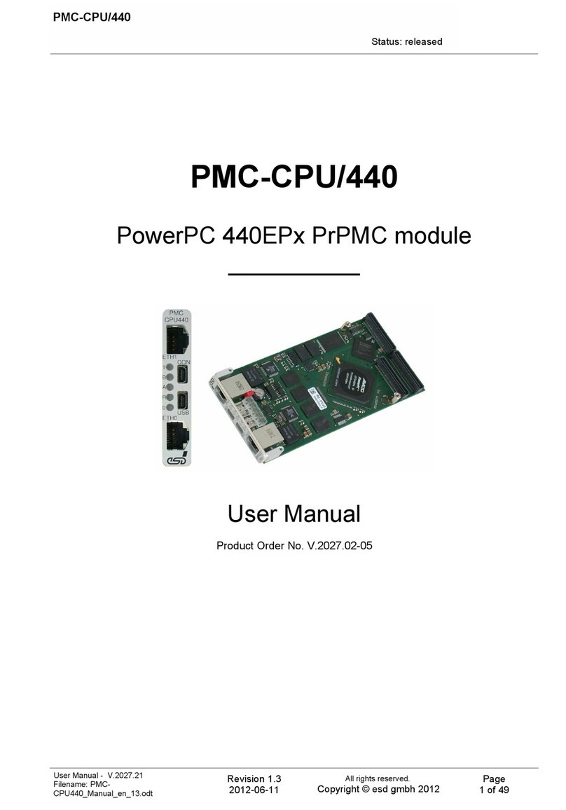
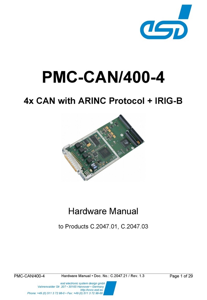
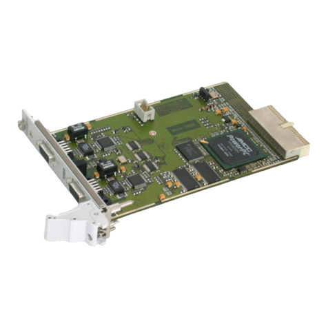
ESD XMC-CPU/T10 User manual

XMC-CPU/T10
XMC/PMC 64-bit PowerPCTM T1022
Processor Board with FPGA
Hardware Manual
to Product V.2030.01
XMC-CPU/T10 Hardware Manual • Doc. No.: V.2030.21 / ev. 1.2 Page 1 of 41
esd electronics gmbh
Vahrenwalder Str. 207 • 30165 Hannover • German
http://www.esd.eu
Phone: +49 (0) 511 3 72 98-0 • Fax: +49 (0) 511 3 72 98-68

N T E
The information in this document has been carefully checked and is believed to be entirely reliable.
esd electronics makes no warranty of any kind with regard to the material in this document, and
assumes no responsibility for any errors that may appear in this document. In particular
descriptions and technical data specified in this document may not be constituted to be guaranteed
product features in any legal sense.
esd electronics reserves the right to make changes without notice to this, or any of its products, to
improve reliability, performance or design.
All rights to this documentation are reserved by esd electronics. Distribution to third parties, and
reproduction of this document in any form, whole or in part, are subject to esd electronics's
written approval.
© 2019 esd electronics gmbh, Hannover
esd electronics gmbh
Vahrenwalder Str. 207
30165 Hannover
Germany
Phone: +49-511-372 98-0
Fax: +49-511-372 98-68
E-Mail: [email protected]
Internet: www.esd.eu
This manual contains important information and instructions on safe and efficient
handling of the XMC-CPU/T10. Carefully read this manual before commencing any work
and follow the instructions.
The manual is a product component, please retain it for future use.
Trademark Notices
PowerPC™ and the PowerPC logo™ are trademarks of IBM in the United States and/or other countries.
VITA™ is a trademark of the VMEbus International Trade Association in the United States and other countries.
PCI Express® is a registered trademark of PCI-SIG.
Linux® is the registered trademark of Linus Torvalds in the United States and/or other countries.
VxWorks® is a registered trademark of Wind iver Systems, Inc.
QNX® is a registered trademark of QNX Software Systems Limited, and are registered trademark and/or used in certain
jurisdictions.
EtherCAT® is registered trademark and patented technology, licensed by Beckhoff Automation GmbH, Germany.
All other trademarks, product names, company names or company logos used in this manual are reserved by their
respective owners.
Page 2 of 41 Hardware Manual • Doc. No.: V.2030.21 / ev. 1.2 XMC-CPU/T10

Document file: I:\Texte\Doku\MANUALS\PMC-XMC\XMC-CPU-T10\XMC-CPU-T10_Hardware_Manual_en_12.odt
Date of print: 2019-10-18
Document type
number: DOC0800
Hardware version: 1.1
Document History
The changes in the document listed below affect changes in the hardware as well as changes in
the description of the facts, only.
Rev. Chapter Changes versus previous version Date
1.1 - First released English manual 2016-12-07
1.2 3. Chapter restructured and description of Ethernet LEDs added 2019-10-18
4. Description of VCCO13, VCCO34 and VCCO35 corrected
Technical details are subject to change without further notice.
XMC-CPU/T10 Hardware Manual • Doc. No.: V.2030.21 / ev. 1.2 Page 3 of 41

Classification of Warning Messages and Safety Instructions
This manual contains noticeable descriptions, warning messages and safety instructions, which
you must follow to avoid personal injuries or death and property damage.
This is the safety alert symbol.
It is used to alert you to potential personal injury hazards. Obey all safety messages
and instructions that follow this symbol to avoid possible injury or death.
DANGER, WARNING, CAUTI N
Depending on the hazard level the signal words DANGE , WA NING or CAUTION are used to
highlight safety instructions and warning messages. These messages may also include a warning
relating to property damage.
DANGER
Danger statements indicate a hazardous situation which, if not avoided, will result in
death or serious injury.
WARNING
Warning statements indicate a hazardous situation that, if not avoided, could result in
death or serious injury.
CAUTI N
Caution statements indicate a hazardous situation that, if not avoided, could result in
minor or moderate injury.
N TICE
Notice statements are used to notify people on hazards that could result in things other than
personal injury, like property damage.
N TICE
This NOTICE statement indicates that the device contains components sensitive to
electrostatic discharge.
N TICE
This NOTICE statement contains the general mandatory sign and gives information that
must be heeded and complied with for a safe use.
INF RMATI N
INF RMATI N
Notes to point out something important or useful.
Page 4 of 41 Hardware Manual • Doc. No.: V.2030.21 / ev. 1.2 XMC-CPU/T10

Safety Instructions
● When working with the XMC-CPU/T10 follow the instructions below and read the manual carefully to
protect yourself from injury and the XMC-CPU/T10 from damage.
● The device is a built-in component. It is essential to ensure that the device is mounted in a way that
cannot lead to endangering or injury of persons or damage to objects.
● Do not use damaged or defective cables to connect the XMC-CPU/T10.
● In case of damages to the device, which might affect safety, appropriate and immediate measures
must be taken, that exclude an endangerment of persons and domestic animals and property.
● Current circuits which are connected to the device have to be sufficiently protected against
hazardous voltage (SELV according to EN 60950-1).
● The XMC-CPU/T10 may only be driven by power supply current circuits, that are contact protected.
A power supply, that provides a safety extra-low voltage (SELV) according to EN 60950-1, complies
with this conditions.
● The device has to be securely installed in the control cabinet before commissioning.
● Protect the XMC-CPU/T10 from dust, moisture and steam.
● Protect the XMC-CPU/T10 from shocks and vibrations.
● The XMC-CPU/T10 may become warm during normal use. Always allow adequate ventilation around
the XMC-CPU/T10 and use care when handling.
● Do not operate the XMC-CPU/T10 adjacent to heat sources and do not expose it to unnecessary
thermal radiation. Ensure an ambient temperature as specified in the technical data.
DANGER
Hazardous Voltage - Risk of electric shock due to unintentional contact with
uninsulated live parts with high voltages inside of the system into which the XMC-
CPU/T10 is to be integrated.
→
→
All current circuits which are connected to the device have to be sufficiently protected
against hazardous voltage (SELV according to EN 60950-1) before you start with the
installation.
Ensure the absence of voltage before starting any electrical work
N TICE
Electrostatic discharges may cause damage to electronic components.
To avoid this discharge the static electricity from your body before you touch the XMC-
CPU/T10.
Qualified Personnel
This documentation is directed exclusively towards personnel qualified in control and automation
engineering. The installation and commissioning of the product may only be carried out by qualified
personnel, which is authorized to put devices, systems and electric circuits into operation according to
the applicable national standards of safety engineering.
Conformity
The XMC-CPU/T10 is a sub-assembly intended for incorporation into an apparatus by a manufacturer
and NOT by the end user. The manufacturer of the final system must decide, whether additional EMC
or EMI protection requirements are necessary.
Data Safety
This device is equipped with an Ethernet or other interface which is suitable to establish a connection to
data networks. Depending on the software used on the device, these interfaces may allow attackers to
compromise normal function, get illegal access or cause damage.
esd does not take responsibility for any damage caused by the device if operated at any networks. It is
the responsibility of the device's user to take care that necessary safety precautions for the device's
network interface are in place.
XMC-CPU/T10 Hardware Manual • Doc. No.: V.2030.21 / ev. 1.2 Page 5 of 41

Intended Use
The intended use of the XMC-CPU/T10 is the operation as XMC/PMC 64-bit PowerPCTM T1022
Processor Board with FPGA.
The guarantee given by esd does not cover damages which result from improper use, usage not in
accordance with regulations or disregard of safety instructions and warnings.
● The XMC-CPU/T10 is intended for installation on a base board according to IEEE 1386.1-2001 (PMC)
or Vita 42.3 (XMC).
● The operation of the XMC-CPU/T10 in hazardous areas, or areas exposed to potentially explosive
materials is not permitted.
● The operation of the XMC-CPU/T10 for medical purposes is prohibited.
Service Note
The XMC-CPU/T10 does not contain any parts that require maintenance by the user. The XMC-
CPU/T10 does not require any manual configuration of the hardware. Unauthorized intervention in the
device voids warranty claims.
Disposal
Devices which have become defective in the long run have to be disposed in an appropriate way or
have to be returned to the manufacturer for proper disposal. Please, make a contribution to
environmental protection.
Typographical Conventions
Throughout this manual the following typographical conventions are used to distinguish technical terms.
Convention Example
File and path names /dev/null or <stdio.h>
Function names open()
Programming constants NULL
Programming data types uint32_t
Variable names Count
Number Representation
All numbers in this document are base 10 unless designated otherwise. Hexadecimal numbers have a
prefix of 0x. For example, 42 is represented as 0x2A in hexadecimal.
Abbreviations
API Application Programming Interface
CAN Controller Area Network
CPU Central Processing Unit
CiA CAN in Automation
HW Hardware
I²C Inter-Integrated Circuit
I/O Input/Output
LSB Least Significant Bit
MSB Most Significant Bit
n.a. not applicable
OS Operating System
PCIe Peripheral Component Interconnect Express
PMC PCI Mezzanine Card
SDK Software Development Kit
USB Universal Serial Bus
XMC PCIe Mezzanine Card
Page 6 of 41 Hardware Manual • Doc. No.: V.2030.21 / ev. 1.2 XMC-CPU/T10

Table of contents
Safety Instructions........................................................................................................................... 5
1. Overview...................................................................................................................................... 9
2. PCB with Connectors..................................................................................................................11
2.1 PCB Top Layer View with Connectors and LEDs.................................................................11
2.2 PCB Bottom Layer View with LED and Coding Switches.....................................................12
3. LEDs.......................................................................................................................................... 13
3.1 Front Panel LEDs.................................................................................................................13
3.1.1 LED Indication of the TriColor LEDs 0-4......................................................................13
3.1.2 Ethernet LEDs (ETH1, ETH2) ....................................................................................13
3.2 CON Activity (LED 1222) and USB PW (LED1230) ..........................................................14
4. Hardware Configuration..............................................................................................................15
4.1 Coding Switches.................................................................................................................. 15
5. Hardware Installation.................................................................................................................. 16
6. Technical Data............................................................................................................................18
6.1 General Technical Data........................................................................................................18
6.2 CPU and Memory................................................................................................................19
6.3 Ethernet Interface................................................................................................................19
6.4 Serial Interfaces...................................................................................................................19
6.4.1 I²C Interface................................................................................................................20
6.5 USB - USB Host Interface....................................................................................................20
6.6 CON - USB Device Interface................................................................................................20
6.7 PMC Interface...................................................................................................................... 21
6.8 XMC Interface .....................................................................................................................21
6.9 Digital In-/Outputs P4...........................................................................................................21
6.10 Digital In-/Outputs P6.........................................................................................................22
6.11 SATA.................................................................................................................................. 22
6.12 eal-Time Clock ( TC)......................................................................................................22
6.13 Health................................................................................................................................ 23
6.14 Memory - Interface.............................................................................................................23
6.15 Software Support...............................................................................................................23
6.16 Firmware License...............................................................................................................24
7. Connector Assignments.............................................................................................................. 25
7.1 USB, (USB Host, X1200).....................................................................................................25
7.2 CON, (USB Device, X1220).................................................................................................25
7.3 Ethernet ETH0, ETH1..........................................................................................................26
7.4 PMC Connectors..................................................................................................................27
7.4.1 PMC P1 Connector.....................................................................................................27
7.4.2 PMC P2 Connector.....................................................................................................28
7.4.3 PMC P4 I/O Connector................................................................................................29
7.5 XMC - P5............................................................................................................................. 31
7.6 XMC - P6............................................................................................................................. 32
7.7 JTAG X900.......................................................................................................................... 33
7.7.1 XMC-CPU-ADAPTE -BDI..........................................................................................33
7.7.2 XMC-CPU-ADAPTE -NXP.........................................................................................34
7.8 Debug Interface X400 and JTAG FPGA Interface X1900.....................................................35
7.8.1 XMC-CPU-ADAPTE -FPGA ......................................................................................35
8. Description of the Units..............................................................................................................36
8.1 CPU..................................................................................................................................... 36
8.1.1 Access Addresses from CPU to FPGA .......................................................................36
8.2 FPGA...................................................................................................................................37
XMC-CPU/T10 Hardware Manual • Doc. No.: V.2030.21 / ev. 1.2 Page 7 of 41
8.2.1 GPIO Modules............................................................................................................. 37
9. Bootloader.................................................................................................................................. 38
9.1 License................................................................................................................................ 38
9.2 Configuration and Console Access......................................................................................38
9.3 Special Commands.............................................................................................................. 39
10. Order Information.....................................................................................................................40
Page 8 of 41 Hardware Manual • Doc. No.: V.2030.21 / ev. 1.2 XMC-CPU/T10

verview
1. verview
Figure 1: Block circuit diagram
The XMC-CPU/T10 is a 64-bit XMC PowerPC Host CPU.
It is equipped with a PMC and an XMC interface.
The NXP® PowerPC® QorIQ® T1022 with 1.2 GHz features two 64-bit e5500 Power Architecture®
processor cores with high performance data path acceleration architecture (DPAA) and network
peripheral interfaces.
The local memory bus is 64 bits wide plus 8 bits ECC with an overall capacity of 512 Mbyte.
16 Mbyte SPI Flash for boot loader and 32 Kbit I²C EEP OM for U-Boot environment offer non-
volatile memory spaces.
The XMC-CPU/T10 features a second 16 Mbyte 'fallback' SPI Flash, used for system recovery if a
system crash occurs during a firmware update. Alternatively it can be used for application software.
The Xilinx® FPGA Artix®-7 is connected to the CPU by local bus for low latency data exchange. For
high bandwidth data exchange the FPGA and the CPU are additionally connected via PCI
Express®. 62 LVTTL-I/Os of the FPGA are routed to the PMC-P4 connector.
The XMC interface comes with 4-lane PCIe bus and is designed according to VITATM 42.3.
The PMC interface supports 32 bit / 66 MHz PCI bus according to PCI Local Bus Specification 3.0.
The XMC-CPU/T10 provides two Gigabit Ethernet interfaces accessible at the front panel, which
give an excellent base for EtherCAT® applications.
The USB host port supports USB 2.0.
The Flash memory carries the standard boot program “Das U-Boot” and enables the XMC-
CPU/T10 to boot various operating systems from on-board Flash, network or USB.
BSPs are available from esd as described in the “Order Information” on page 40. The BSPs
include an example source code for the FPGA. Programming of the FPGAs is done via XILINX
Toolchain.
The esd EtherCAT® Master Stack is available for the BSPs developed by esd (see page 40).
XMC-CPU/T10 Hardware Manual • Doc. No.: V.2030.21 / ev. 1.2 Page 9 of 41

verview
Customization of the XMC-CPU/T10 is available on request:
CAN
esd offers standard PIM modules for CAN signals (see Alternative Signal Names in chapter “PMC
P4 I/O Connector”, page 29)
Furthermore, a CAN IP-core (CAN esdACC) is available on request, implemented in a customized
configuration (number of CAN nodes, routing FPGA ↔ P4).
I/ s via P6
Additional 73 LVTTL I/Os at connector P6 or 34 LVDS I/Os are available on request as well as a
Serial ATA interface.
CPU Type
Furthermore, other CPU-types (T1014, T1042) are applicable, also an additional M AM and other
serial interfaces ( S-232) via P4.
Flash
Up to 2x 128 MByte Flash is available on request.
RAM
Up to 2 GByte DD 3 AM is available.
PMC only
The XMC-CPU/T10 can be produced without the connectors P5 and P6 if the space on the carrier
is limited.
All these options are available for customized serial production in reasonable quantities.
Please contact our sales team for detailed information.
Page 10 of 41 Hardware Manual • Doc. No.: V.2030.21 / ev. 1.2 XMC-CPU/T10

PCB with Connectors
2. PCB with Connectors
2.1 PCB Top Layer View with Connectors and LEDs
Figure 2: PCB top view
N TICE
ead chapter “Hardware Installation” on page 16 before starting the installation of the
hardware!
See also page 25 and following for signal assignments of the connectors.
The JTAG connectors and the Debug-interface connector have to be connected on the PCB
bottom side of XMC-CPU/T10 (see Figure 3 for the position of the connectors and pins).
XMC-CPU/T10 Hardware Manual • Doc. No.: V.2030.21 / ev. 1.2 Page 11 of 41

PCB with Connectors
2.2 PCB Bottom Layer View with LED and Coding Switches
Figure 3: PCB bottom view
The Debug interface (X900) and the JTAG interfaces (X400, X1900) must be connected from the
bottom side of the XMC-CPU/T10.
See also page 25 and following for signal assignments of the connectors.
esd offers special adapters as accessories, see “Order Information” on page 40.
The coding switches are described on page 15.
Page 12 of 41 Hardware Manual • Doc. No.: V.2030.21 / ev. 1.2 XMC-CPU/T10

LEDs
3. LEDs
3.1 Front Panel LEDs
Figure 4: Connectors and LEDs
3.1.1 LED Indication of the TriColor LEDs 0-4
Five TriColor LEDs are equipped in the front panel.
LED Colour Description
Signal name
in schematic
diagram
LEDX
green User-defined via I²C bus and driver,
for a description of the Special Commands see page 39
LED10XG
red LED10X
blue LED10XB
(X = 0-4)
Table 1: LEDs 0 - 4
3.1.2 Ethernet LEDs (ETH1, ETH2)
Each Ethernet interface comes with a green Activity LED and a yellow Link LED. The LEDs are
integrated in the J45 sockets of the Ethernet interfaces ETH0 and ETH1.
LED Colour Indication Indicator
state Description (LED on)
LNKx yellow Link ON Ethernet link is established for ETHx,
Ethernet bit rate: 10/100/1000 Mbit/s
ACTx green Activity Flickering Ethernet activity on ETHx
(reception and transmission of Ethernet data)
(x... 0, 1)
Table 2: Ethernet LEDs Activity and Link
XMC-CPU/T10 Hardware Manual • Doc. No.: V.2030.21 / ev. 1.2 Page 13 of 41

LEDs
3.2 C N Activity (LED 1222) and USB PWR (LED1230)
The LEDs C N Activity and USB PWR are equipped on the rear side of the XMC-CPU/T10, see
Figure 3 page 12.
LED Colour Indication Description (LED on)
LED name
in schematic
diagram
C N Activity green Activity Data transfer on terminal interface CON LED1222
USB PWR green Power 5 V power supply voltage of USB interface on LED1230
Table 3: LEDs CON Activity and USB PW
Page 14 of 41 Hardware Manual • Doc. No.: V.2030.21 / ev. 1.2 XMC-CPU/T10

Hardware Configuration
4. Hardware Configuration
4.1 Coding Switches
Figure 5: Coding switches
On delivery the DIP switches are all off.
Coding
Switch Pin Description
Signal name
in schematic
diagram
Board
Cfg
1 VCCO35 ON 3.3V I/O-voltage on FPGA, Bank 35
SW2000
OFF 2.5V I/O-voltage on FPGA (for LVDS), Bank 35
2 VCCO34 ON 3.3V I/O-voltage on FPGA, Bank 34
OFF 2.5V I/O-voltage on FPGA (for LVDS), Bank 34
3 VCCO13 ON 3.3V I/O-voltage on FPGA, Bank 13
OFF 2.5V I/O-voltage on FPGA (for LVDS), Bank 13
4 SPI_SEL Exchange SPI-Flash order
User
Cfg
1 LC_IO23
GPIO for user configuration SW901
2 LC_IO22
3 LC_IO21
4 LC_IO20
User
Cfg
1 LC_IO15
GPIO for user configuration SW900
2 LC_IO14
3 LC_IO13
4 LC_IO12
Table 4: Coding Switch SW2000, SW901, SW900
XMC-CPU/T10 Hardware Manual • Doc. No.: V.2030.21 / ev. 1.2 Page 15 of 41

Hardware Installation
5. Hardware Installation
N TICE
Read the safety instructions at the beginning of this document carefully, before
you start with the hardware installation!
DANGER
Hazardous Voltage - Risk of electric shock due to unintentional contact with
uninsulated live parts with high voltages inside of the system into which the XMC-
CPU/T10 is to be integrated.
→ Disconnect all hazardous voltages (mains voltage) before opening the system.
→ Ensure the absence of voltage before starting any electrical work.
N TICE
Electrostatic discharges may cause damage to electronic components.
→
→
To avoid this, please discharge the static electricity from your body before you touch
the XMC-CPU/T10.
Furthermore, you should prevent your clothes from touching the XMC-CPU/T10,
because your clothes might be electrostatically charged as well.
Procedure:
1. Switch off your system and all connected peripheral devices (monitor, printer, etc.).
2. Discharge your body as described above.
3. Disconnect the system from the mains.
DANGER
Hazardous Voltage
Risk of electric shock due to unintentional contact with uninsulated live parts with
high voltages inside of the system into which the XMC-CPU/T10 is to be integrated.
→
→
→
→
Disconnect all hazardous voltages (mains voltage) before opening the system.
If the system does not have a flexible mains cable, but is directly connected to
mains, disconnect the power supply via the safety fuse and make sure that the fuse
cannot switch on again unintentionally (i.e. with caution label).
Ensure the absence of voltage before starting any electrical work
Cover or block off adjacent live parts.
4. Open the case if necessary.
5. For sufficient EMC shielding the XMC-CPU/T10 should make contact to the system's
enclosure nearly completely around its front panel. For this purpose a conductive O-ring is
contained in the product package of the XMC-CPU/T10 module. Mount the conductive O-ring
on the front panel of the XMC-CPU/T10. Additionally or instead of it use shielding material as
for example conductive shielding gasket.
6. emove the carrier board (if already installed) and plug the XMC-CPU/T10 carefully on the
carrier board. Pay attention that the XMC-CPU/T10 is correctly installed on the carrier board.
Fix the XMC-CPU/T10 with the screws on the carrier board. Use the four M 2.5 x 6 mm
screws which are contained in the product package of the module.
7. Install the carrier board in your system.
8. Close the system's case again (if necessary).
Page 16 of 41 Hardware Manual • Doc. No.: V.2030.21 / ev. 1.2 XMC-CPU/T10

Hardware Installation
9. Connect the Ethernet and the USB interfaces via the connectors in the front panel of the
XMC-CPU/T10.
10. Connect the system to mains again (mains connector or safety fuse).
11. Switch on the system and the peripheral devices.
12. End of hardware installation.
13. Set the interface properties in your operating system. efer to the documentation of the
operating system.
XMC-CPU/T10 Hardware Manual • Doc. No.: V.2030.21 / ev. 1.2 Page 17 of 41

Technical Data
6. Technical Data
6.1 General Technical Data
Power supply
voltage
Nominal voltage: 3.3 V / I3.3V_MAX = 800 mA, I3.3V_TYPICAL = 750 mA,
and, depending on slot used:
PMC interface:
5V / I5V_MAX = 1.4 A, I5V_TYPICAL = 1 A
XMC interface:
12V / I12V_MAX = 600 mA, I12V_TYPICAL = 550 mA
Absolute maximum power: P3.3V+5V_MAX = 10 W
Connectors
ETH0
ETH1
J45 socket (X1300) - Ethernet Port 0
J45 socket (X1400) - Ethernet Port 1
CON Mini USB socket type-B (X1220) - Console (USB-Device)
USB Mini USB socket type-AB (X1200) - USB-Host
PMC P1
PMC P2
PMC P4
XMC P5
XMC P6
64-pin PMC connector (P1) - PMC PCI part 1
64-pin PMC connector (P2) - PMC PCI part 2
64-pin PMC connector (P4) - PMC IO
XMC, Samtec ASP-103614-04 - PCI Express interface
XMC, Samtec ASP-103614-04 - e.g.: 73 LVTTL
or 34 LVDS I/Os
Only for test- and programming purposes:
Debug Samtec CLM108-02-F-D-BE (pass-thru micro socket, X900)
- Debug interface of the CPU and the Health Controller
JTAG Samtec CLM104-02-F-D-BE (pass-thru micro socket, X400),
- JTAG interface additionally via XMC-P1 and P2
FPGA-JTAG Samtec CLM104-02-F-D-BE (pass-thru micro socket, X1900),
- JTAG interface for FPGA
Temperature
range
Operating temperature: 0 °C ... + 55 °C ambient
Storage temperature: -20 °C ... + 70 °C ambient
Cooling method Convection cooling
Humidity 0% ... 90%, non-condensing
Dimensions 149 mm x 74 mm x 10 mm
Weight ca. 150 g with heat sink
Table 5: General data of the module
Page 18 of 41 Hardware Manual • Doc. No.: V.2030.21 / ev. 1.2 XMC-CPU/T10

Technical Data
6.2 CPU and Memory
CPU NXP PowerPC QorIQ T1022, 1.2 GHz, 64-bit, e5500 core
double precision floating point unit
AM 512 Mbyte AM 64-bit wide plus 8 bits ECC DD 3 AM
Flash memory (SPI) 2x 16 Mbyte SPI FLASH for boot loader
EEP OM 1x 32 Kbit I²C EEP OM for U-Boot environment,
1x 4 Kbit AM SPD info DD AM,
1x 32 Kbit EEP OM for Bootstrapping
Table 6: CPU and memory
6.3 Ethernet Interface
Number of Ethernet
interfaces 2x Gigabit Ethernet (ETH0, ETH1)
Standard IEEE 802.3, 10BASE-T, 100BASE-TX, 1000BASE-T
Bit rate 10/100/1000 Mbit/s
Connection Twisted Pair (compatible to IEEE 802.3),
Electrical isolation Via transformer,
1500Vrms / 2250 VDC
Connector 2x at J-45-socket in the front panel
Table 7: Data of the Ethernet interfaces
6.4 Serial Interfaces
Number 2 asynchronous serial interfaces
Standard EIA/TIA-232E
Controller integrated in CPU
Bit rate Value range: 9600 Baud to 115200 Baud
Default setting: 115200 Baud, 8 Bit, No Parity 1 Stop-Bit
Physical Interface Port 0: USB 2.0
Port 1: S232
Software Standard operating system drivers
Connectors Port 0: miniUSB Type B
Port 1: via P4 (PMC)
Table 8: Data of the Ethernet interfaces
XMC-CPU/T10 Hardware Manual • Doc. No.: V.2030.21 / ev. 1.2 Page 19 of 41

Technical Data
6.4.1 I²C Interface
Number 1
Standard I²C-Bus Specification ev. 6
Bit rate 100 kbit, optional 400 kbit
Topology Controller integrated in CPU
Physical Interface 3,3 V, not 5V tolerant
1. I2C interface Devices: CPU Setup EEP OM, DD 3 AM SPD EEP OM, TC, LEDs
2. IC2 interface Devices: PCIe to PCI Bridge, Health Controller, U-Boot Env EEP OM.
3. I2C interface Devices: FPGA, Connector P4 Pin 63 SDA Pin 64 SCL.
Table 9: Data of the I²C interface
6.5 USB - USB Host Interface
Number 1x USB host
Standard USB 2.0, max. 480 Mbit/s
Topology Host Controller integrated in CPU
Max. current per
port @5V
500 mA, short-circuit-protected
Electrical isolation None
Software support - OHCI-Host controller- and device driver
- driver of the operating system
Connector Mini USB type-AB socket in the front panel (USB)
Table 10: Data of the USB Host interface USB
6.6 C N - USB Device Interface
Number 1x Console (serial)
Standard USB 2.0 Full-Speed, the first serial interface of the CPU is provided via
an FTDI FT232 chip as USB Device.
The FT232 chip is bus powered.
Electrical isolation Via digital isolator
Connector Mini USB type-B socket in the front panel (CON)
Table 11: Data of the USB Device interface CON
Page 20 of 41 Hardware Manual • Doc. No.: V.2030.21 / ev. 1.2 XMC-CPU/T10
This manual suits for next models
1
Table of contents
Other ESD Computer Hardware manuals

ESD
ESD PMC-CPU/440 User manual

ESD
ESD VME-PMC-CPU/2 User manual

ESD
ESD EPPC-405-UC User manual

ESD
ESD VME-DIO32-C User manual

ESD
ESD PMC-CAN/400-4 User manual

ESD
ESD VME-DIO32-L User manual

ESD
ESD CPCI-DP-2S User manual

ESD
ESD CPCI-ASIO4 User manual

ESD
ESD CAN-PCI/402 User manual

ESD
ESD CAN-M.2/402-2-FD User manual