Soundoff Signal nERGY bluePRINT ENGND04101 User manual

EVCS_Remote Node_ENGND04101 1.15
1.800.338.7337 / www.soundoffsignal.com
NOTICE:
Installers and users must comply with all applicable federal, state and local laws regarding use and installation of warning devices.
Improper use or installation may void warranty coverage. To review our Limited Warranty Statement & Return Policy for this or any SoundOff Signal product, visit our website at
www.soundoffsignal.com/sales-support. If you have questions regarding this product, contact Technical Services, Monday - Friday, 8 a.m. to 5 p.m. at 1.800338.7337 (press #4 to skip the
automated message). Questions or comments that do not require immediate attention may be emailed to [email protected].
SUPERIOR CUSTOMER RELATIONSHIPS. SMARTLY DESIGNED LIGHTING & ELECTRONIC SOLUTIONS.
1
Please see next page for
Technical Specifications
REMOTE NODE
PART NUMBER: ENGND04101
The Remote Node provides 10 outputs for connection to
vehicle devices (50 Amps max).
•(4)10-ampsolidstateswitchableoutputs
•(6)5-ampsolidstateswitchableoutputs.
TheRemoteNodealsoprovides4inputstocontrolsystems.
•ActiveHigh/Lowselectable.
See attached Install Template to aid in connections and programming
+(Power)
-(Ground)
Wire
Pin #
Wire
Function Amp
1 OUTPUT 9 10 Amp
2 OUTPUT 8 5 Amp
3 OUTPUT 7 10 Amp
4 OUTPUT6 5 Amp
5 OUTPUT 5 5 Amp
6 OUTPUT4 10 Amp
7 OUTPUT 3 5 Amp
8 OUTPUT 2 10 Amp
9 OUTPUT 10 5 Amp
10 INPUT 1*
11 INPUT 2
12 INPUT 3
13 INPUT4
14 ADDRESS
SELECT
15 DATA
16 OUTPUT 1 5 Amp
PIN 1
PIN 8
PIN16
PIN 9
OUTPUTINDICATORLED’S
FOROUTPUTS1-10
10
1
ADDRESSINDICATORLED
DIAGNOSTICINDICATORLED
ACTIVELOW
ORHIGH
MOMENTARY
ACTIVEHIGH
AUTOMOTIVE50
AMP MAX FUSE
OR BREAKER
*Input1canbeusedasgeneralpurposeinput
orasasystemignitioninput.
Higherinrushcurrentthreshold-Xenon
VBATT
DIRECTBATTGROUND
CONNECTION
•HIGHCURRENTinterconnectsmustbeproperlyterminated.Poorcrimpqualitycancauseheat
build-upandre.Followcrimpconnectormanufacturerinstructions.
•DONOTinstallthisproductorrouteanywiresintheAirBagDeploymentZone.Refertovehicle
Owner’sManualfordeploymentzones.
•DoNOTusesystemtodisconnectheadlights,brakelightsorothersafetyequipment.
•Unitmaybecomehottotouchduringnormaloperation.
•Failuretoproperlyinstallconnectors,fusesorwiringmaycausevehiclefailureorre.
•Installationmustonlybeperformedbytrainedtechnician.Installermustdeterminevehiclewiring
congurationandproperintegrationofsystem.
•Useproperwiregauge.Allpowerwiresconnectingtopositive(+)ornegative(-)batteryterminal
orlocalchassisground(-)mustbesizedtosupplyatleast125%ofmax.currentandproperlyfusedat
powersource.
•Installprotectivegrommetswhenroutingwirethroughrewallormetal.
WARNING

EVCS_Remote Node_ENGND04101 1.15
1.800.338.7337 / www.soundoffsignal.com
NOTICE:
Installers and users must comply with all applicable federal, state and local laws regarding use and installation of warning devices.
Improper use or installation may void warranty coverage. To review our Limited Warranty Statement & Return Policy for this or any SoundOff Signal product, visit our website at
www.soundoffsignal.com/sales-support. If you have questions regarding this product, contact Technical Services, Monday - Friday, 8 a.m. to 5 p.m. at 1.800338.7337 (press #4 to skip the
automated message). Questions or comments that do not require immediate attention may be emailed to [email protected].
SUPERIOR CUSTOMER RELATIONSHIPS. SMARTLY DESIGNED LIGHTING & ELECTRONIC SOLUTIONS.
2
SETTING NODE ADDRESS
To set the node addresses:
1.MomentarilyconnectpowertoPIN14.
2.AddressindicatorLEDwillwinktheaddress(1-5).
NOTE:
•Defaultaddressis1.
•Afteraddress1issetitwillcyclethroughtheaddressesuntilitgetsbackto1.
DIAGNOSTIC LED
•ThediagnosticLEDissteadyonwhenthedeviceispoweredupandrunningwithnoerrors.
•ThediagnosticLEDisoffwhenthedeviceisofforinsleepmode.
•ThediagnosticLEDwinkswhenthereisasystemfaultofthedeviceisinrmwareupgrademode.
•FaultconditionisreadbycountingthenumberoftimestheLED
“winks”on.Eachfaultconditionwillgenerateapatternwhereeach“wink”is250ms
off/250mson.ThepatternisterminatedbytheLEDbeingofffor2.5seconds.
•TheLEDwillwinkmultiplepatternswhenmorethanonefaultconditionisactive.
FAULT CONDITION PATTERNS:
1Wink-RPDUoutput(s)arefaulted
2Winks-Communicationfault
3Winks-Sourcevoltagelevelis<9VDC
4Winks-Sourcevoltagelevelis>16VDC
5Winks-Overtemperaturecondition
Bydefaultevenoutputsashalternatingwithoddoutputs.
Tech Specs
nERGY Control System Remote
Node
Input Voltage: 10-16Vdc(NegativeGround)
Maximum Input Current: 50 Amps (30Amps at 85°C)
Outputs (Sum of ALL used Outputs
Shall Not Exceed 50Amps)
4x10AmpSolidState,Switched
6x5AmpSolidState,Switched
IGN ON: Standby Current: 60mA
IGN OFF: Sleep Current: 0.34mA
Inputs:
4xTotal
3xActiveHigh/LowInputs
*1xActivehigh/LowInputw/SystemWakeup
Reverse Polarity Protection: NotProtected(ReversePolaritywillDestroytheDevices)
Transient Protection: Protected
High Voltage Protection: >16V;HighVoltageErrorCodeSet
Low Voltage Protection: <9V;LowVoltageErrorCodeSet
Operating Temp: -40˚Cto+65˚C(85°Cmaxcurrent=30Amps)
Dimensions: 6.0”x3.4”x.8”
Weight, Boxed: 13.2oz.
Weight, Device Only: 10.7oz.
Valid Input Threshold High: >8.0V
Valid Input Threshold Low: <1.5V
Hermeticallysealedprovidingprotectioninwetareas.
•Installfuseorbreaker(50Ampsmax.)onmainpowersupply.
•DoNOTconnectproducttostrobepowersupply.Productisself-contained;noexternalpowersupply
needed.
•FollowattachedWiringandInterconnectrequirements.
•Torque the provided M8 nuts with lock washer to a maximum of 7ft-lbs.
-Verify that the lockwasher is fully seated when assembled-
WARNING
*Input1canbeusedtosenseignitionstatusforoverallsystemoperation
Multi-colorlightsshouldbedrivenbyoutputswithinthesameoutputgroup
(Group1:1-5,Group2:6-10)toaligntiming.
Bydefaultevenoutputsashalternatingwithoddoutputs.

EVCS_Remote Node_ENGND04101 1.15
1.800.338.7337 / www.soundoffsignal.com
NOTICE:
Installers and users must comply with all applicable federal, state and local laws regarding use and installation of warning devices.
Improper use or installation may void warranty coverage. To review our Limited Warranty Statement & Return Policy for this or any SoundOff Signal product, visit our website at
www.soundoffsignal.com/sales-support. If you have questions regarding this product, contact Technical Services, Monday - Friday, 8 a.m. to 5 p.m. at 1.800338.7337 (press #4 to skip the
automated message). Questions or comments that do not require immediate attention may be emailed to [email protected].
SUPERIOR CUSTOMER RELATIONSHIPS. SMARTLY DESIGNED LIGHTING & ELECTRONIC SOLUTIONS.
3
Wiring and Interconnect Requirements for ENGND04101 Remote Node
•Highcurrentinterconnectsrequirecarefulterminationwiththeproperequipment. WARNING! Poor crimp quality can cause significant heat build-up and fire.Followconnector
manufacturerinstructionstoterminateproperly.
•RemoteNodecanswitchuptoatotal maximum of 50Amps.Usermustcongureoutputstonotexceedthistotalcurrent.Individualoutputswitchesareratedupto10Ampseachforhigher
currentloads,but the total device current must not exceed 50Amps.Thesoftwarewarnswhentheselimitsareexceededandusermustensurethatindividualoutputlimitsandtotaldevice
current limits are not exceeded in normal use.
•Do not gang or parallel multiple outputs to drive a high current load. Multiple5Ampand10Ampoutputsmustnotbecombinedtoachieveahighercurrentlimit.
TERMINATION OPTION 2
Purchaseindividualconnectorcomponentstoterminatethewiresattheconnector.
Molex P/N:19418-0030 Molex P/N:19420-0001 Molex P/N: 19417-0119
MX150L™16CircuitSealed
Receptaclefor14-16AWGWire
MX150L™FemaleTerminalfor14-16AWG
Wire,TinPlated
MX150L™SocketPlug/Key(Oneplugre-
quiredforeachunusedpinlocationtoseal)
•MX150LAssemblyInstructions:http://www.molex.com/pdm_docs/as/AS-19417-001.pdf
•ApplicationToolingSpecicationSheet:http://www.molex.com/pdm_docs/ats/ATS-6381144HM.pdf
•QualityCrimpingHandbook:http://www.molex.com/pdm_docs/ats/TM-638000029.pdf
•Actualterminalandhousingsmaybedifferentdependingonapplication,wiretype,etc.
•HandCrimpTool:Molex P/N:63811-4400
•ManualExtractionTool: Molex P/N:63813-1500
•WARNING! Wire diameter with insulation must be 0.113in to 0.139in (2.87mm-3.53mm) to properly seal
(suchasSXL16AWG)
Pros: •Consistentwirecolors,cleaninstallwithoutbutt-splices
Cons: •Needtopurchasecrimperandtrainpersonnel
WARNING
TERMINATION OPTION 1
PurchaseaccessorymatingharnessfromSoundOffSignal
SoundOff P/N:ENGHNK02(16pinMatingHarness)
•Typicallyawatertightbutt--splicewithglueisusedto
protectthisterminationandisrequiredforexterioruse.
Pros: •No need to terminate at the connector pins
•NoneedtopurchaseMolexcrimper
Cons: •Requiresbutt-spliceoralternateconnector
•Requiresheatshrinktubingwithglueforexterior
Striptothislength
(drawntoscale)
0.165”to0.197”
Insulation
Crimp
0.006”to
0.026”

4
?
Pin 1, Output 9, 10A _ _________________________________ ________________
Pin 2, Output 8, 5A __________________________________ _______________
Pin 3, Output 7, 10A __________________________________ _______________
Pin 4, Output 6, 5A ____________________________________ _______________
Pin 5, Output 5, 5A ____________________________________ _______________
Pin 6, Output 4, 10A __________________________________ _______________
Pin 7, Output 3, 5A __________________________________ _______________
Pin 8, Output 2, 10A __________________________________ _______________
________________ __________________________________ 5A, Output 1, Pin 16
________________ __________________________________ 5A, Output 10, Pin 9
________________ ______________________________________ Input 1, Pin 10
________________ ______________________________________ Input 2, Pin 11
________________ ______________________________________ Input 3, Pin 12
________________ ______________________________________ Input 4, Pin 13
ID # __________ Module Select, Pin 14
________________ ________________________________________ DATA, Pin 15
EVCS_RemoteNode1.15
1.800.338.7337 / www.soundoffsignal.com
Department: _________________________________
Vehicle: ______________________________________
Installer / Date: ________________________________
Moun ng Loca on: _____________________________
REMOTE NODE
INSTALL TEMPLATE
AUTOMOTIVE50AMAX
FUSE OR BREAKER
Function WireColorFunction
WireColor
=XenonInrush
Popular Computer Hardware manuals by other brands

Waveshare
Waveshare High-Precision AD/DA Board user manual
Cypress Semiconductor
Cypress Semiconductor CY7C1041DV33 Specification sheet
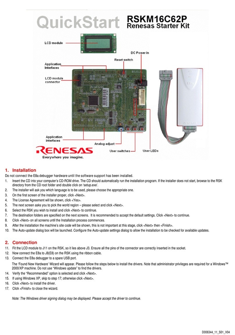
Renesas
Renesas RSKM16C62P quick start

Vorsis
Vorsis VP8 Plus Application note
Moxa Technologies
Moxa Technologies DA-661 Quick installation guide

Rosewill
Rosewill PB360-RGB instruction manual

Intel
Intel E5420 - CPU XEON QUAD CORE 2.50GHZ FSB1333MHZ 12M LGA771 HALOGEN FREE... datasheet

Epson
Epson S1C63000 Core cpu manual
Cypress Semiconductor
Cypress Semiconductor Quad HOTLink II CYV15G0404RB Specification sheet

Telit Wireless Solutions
Telit Wireless Solutions BlueMod+S42 Hardware user's guide
Congatec
Congatec COM Express conga-TCV2 user guide

Sony
Sony DSBK-210 installation instructions
