SoundRanger Compact 2M 40SF2M70M User manual

SoundRanger COMPACT 2M
Model 40SF2M70M (RP1-70M)
Portable Address System
User Guide
Introduction
The SoundRanger COMPACT 2M System is a compact, easy to use way for you to talk to
any audience anywhere.
Because it uses radio waves, there are no microphone cables to get in the way.
You can use the microphone up to 30 metres away from the speaker and even have the
speaker in another room.
If you need more volume or wider distribution, you can use as many COMPACT 2M
speakers as you like with one microphone. However you can’t use more than one radio
microphone with the system. You can also add a COMPACT 2X extension speaker
cabinet, which will increase the power of the system to 120 watts.
The sound quality is crisp and clear; speech intelligibility is excellent.
Because the system is DTI approved (to MPT1345), you don’t need a licence and can use
it anywhere, inside or outside.
Quick Start
To get the best from the system you really ought to read the instructions, but, if you can’t
wait, this is what you do:
1) Position the COMPACT 2M anywhere suitable, preferably at head height or higher
2) Set the controls on the back panel as follows:
Channel 1 Volume (red knob): No 3
Channel 2 Volume (green knob): Zero
Aux/Cable Mic Volume (blue knob): Zero
3) Switch the Power switch to on
4) Switch the microphone on
5) Talk directly into the microphone
Yes, it’s as simple as that.
If you need any advice or assistance, please
contact Connevans Ltd on 01737 247571
2
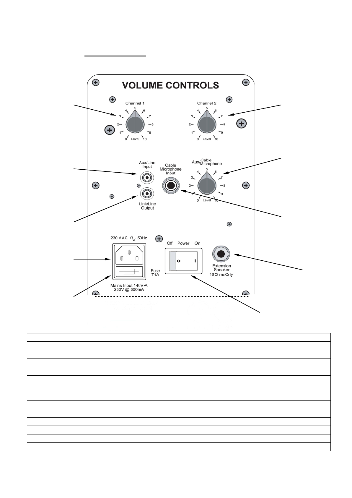
Control Panel
1 2
3
4
6
5
8
7
9 0 10
No
Control
Function
1
Channel 1 Volume
Controls the level of the wireless microphone receiver
2
Channel 2 Volume
Controls the level of second microphone receiver (if fitted)
3
Aux Input Control
Controls the level of Aux/Line input and plug-in wired microphone
4
Input Socket
Phono socket for line level Aux Input - CD player etc
5
Output Socket
Phono socket for line level output for recording or linking with
another Amplifier (Any number of 2M’s may be linked together)
6
Input Socket
6.3mm mono micrphone input socket
7
Output Socket
Jack extension speaker socket (16 ohm only) for COMPACT 2X
8
Socket
230 volt, 50 Hz standard mains input socket
9
Fuse
Mains fuse (T 1 A)
10
Switch
Mains on / off switch

3
Operating Instructions
Positioning:
The COMPACT 2M should be placed on a suitable stand (e.g. the SoundRanger SS-SX1
heavy-duty tripod stand). There is a “top hat” socket in the base of the unit, which will fit on
a standard 36mm diameter tube. It is always best to keep the speaker above the heads of
your audience and in front of the microphone.
Operating:
Switch on the COMPACT 2M and turn the Channel 1volume knob up to about number 3.
Switch on the microphone and talk normally directly into the grille.
You can adjust the volume to suit your audience, but, in order to avoid feedback (high
pitched whistling), do not point the microphone directly at the loudspeaker or stand directly
in front of the loudspeaker. If you are in a confined space, you may experience feedback
at lower levels, in which case you should turn down the volume.
Auxiliary Input
There is an auxiliary input channel on the COMPACT 2M, which can be used for:
•A normal cable microphone (i.e. not a radio microphone). The microphone should be
plugged into the Cable Microphone Input, using a jack plug.
•A Line level sound source (e.g. a CD player, a cassette player or a mixer). This sound
source should be plugged into the phono socket which is labelled “Aux/Line Input”.
Line Output
The phono socket marked Link/Line Output can be used as a line output or to link with
another COMPACT 2M amplifier.
COMPACT 2M Specifications
Model Number
RP1-70M
Radio Receiver
Built-in
Aerial (Antenna)
Built-in
Carrier Frequency
MPT1345 approved (173.8 to 175 MHz)
Oscillation Mode
Quartz controlled
Max Deviation
15 kHz
Power Output
120 Watts into an 8 ohm load
(70 watts into internal speakers)
Freq. Response
100 Hz to 15kHz – speech tailored
THD
<1%
Additional Inputs
Cable (wired) microphone or line level
Speakers
Pair of super-high sensitivity 5 inch full range
Dimensions (mm)
310L x 190W x 345H
Weight
9 Kg
4
Operating Instructions for the MH-203 hand-held radio-
microphone and the MT-103 belt-pack transmitter with the MU-33
headset microphone or the MU-50 lapel microphone follow on
pages 4 and 5.
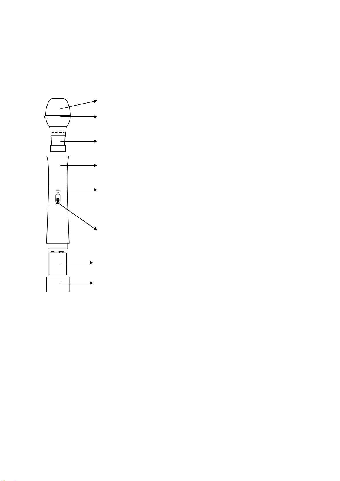
RMH-203 Hand-Held Radio-Microphone
Battery Installation
Unscrew the battery cover and insert a 9-volt alkaline battery, being careful to observe the correct polarity.
Screw the battery cover back in position to hold the battery in contact. When the microphone is switched on,
the battery indicator should flash once. If no flash occurs, please check the polarity and make sure the
battery is fully charged.
Operation
Switch on the microphone; the battery indicator should flash red once.
Switch on the amplifier, turn the volume up a little way and speak directly into the microphone.
Best results will be obtained by speaking fairly close to the grille (20 to 40 mm).
You can adjust the volume to suit your audience, but, to avoid feedback (high pitched whistling), do not point
the microphone directly at the loudspeaker or stand directly in front of the speaker. If you are in a confined
space, turn the volume down.
When you are not using the microphone, turn it off to prolong the battery life.
1) Windshield Grille Protects the cartridge and prevents breath noise
2) Anti-Roll Ring Prevents microphone from rolling when on a flat
surface
3) Cartridge Converts the acoustic signals into electrical signals
4) Microphone Casing Houses and protects the transmitter and
components
5) Battery Indicator Indicates the battery status.
Normal: flashes red when microphone is switched on
Low Battery: red light remains permanently on
Dead Battery: does not light at all
6) Microphone On/Off Switch
7) Battery PP3 9 Volt Alkaline
8) Battery Compartment Unscrew to replace battery
5
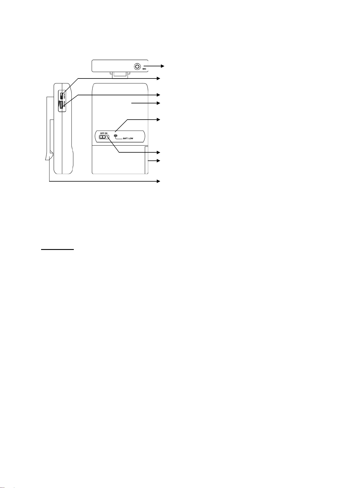
RMT-103 Belt-Pack Transmitter
For use with the MU-33 headset microphone or the MU-50 lapel microphone
Battery Installation
Push and slide down to open the battery compartment. Fit a 9 Volt PP3 alkaline battery, being careful to
observe the correct polarity. Push and slide up to close the battery compartment. When the transmitter is
switched on, the battery indicator should flash red once. If no flash occurs, please check the polarity and
make sure the battery is fully charged.
Operation
Headset Microphone:
Follow the instructions provided with the headset microphone.
Lapel Microphone: plug the lapel microphone into the input socket of the belt-pack transmitter. Locate
and push the connector home and tighten the locking ring. Clip the microphone onto your clothing with the
capsule pointing upwards towards your lips. Best results will be obtained if you fix the microphone as close
to your mouth as possible. When speaking, try to keep you head level and pointing straight ahead so that the
microphone picks up your voice evenly. If feedback (high-pitched whistling) is a problem, try reducing the
Speech Clarity control on the amplifier.
You can clip the belt-pack to your clothing or put it in your pocket.
Belt-Pack Transmitter:
Leave the GT-MT switch set to MT. Set the volume control on the belt-pack about half way up and use the
amplifier volume control to adjust the loudness to suit your audience. If you wish to adjust the volume while
speaking, you can do so from the belt-pack.
Switch on transmitter; the battery indicator should flash red once.
Switch on the amplifier, turn the volume up a little way and speak normally into the headset or lapel
microphone.
You can adjust the volume to suit your audience, but, to avoid feedback (high pitched whistling), do not stand
directly in front of the speaker. If you are in a confined space, turn the volume down.
When you are not using the transmitter, turn it off to prolong the battery life.
1) Input Socket Connect to a headset or
lapel microphone
2) GT- MT Switch Leave this set at MT
3) Volume Control Adjust to suit
4) Belt Pack Casing To house and protect the
transmitter and components
5) Battery Indicator Indicates the battery status:
Normal: flashes red when the unit is switched on
Low Battery: red light remains on
Dead Battery: does not light at all
6) On/Off Switch
7) Battery Compartment
8) Detachable Belt Clip Pull outwards and
press down in the direction of the arrow
to release the belt clip
Table of contents


