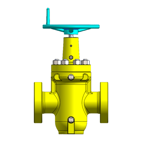
Source VERSA-SLAB User manual

SOURCE VERSA GATE VALVES
API 6A LICENSE
LICENSE NO. 6A-0541 API 6D LICENSE
LICENSE NO. 6D-0477
Issued 210723
VERSA-SLABTM GATE VALVES

SOURCE VERSA VALVES
Table of Content
VERSA VALVE FEATURES
Versa Slab-LS Gate Valve Brochure
Versa Slab-HS Gate Valve Brochure
TECHNICAL INFORMATION
Valve Reference Dimensions and Weights
Recommended Flange Bolt Lengths and Ring Gasket
Gate Valve Trim Chart
OPERATING AND SERVICE MANUAL
Versa-Slab-LS Gate Valve
Versa-Slab-HS Gate Valve
Versa-Slab High Pressure Gate Valve

Drilling & Production API 6A Gate Valve
API 6A LICENSE
LICENSE NO. 6A-0541
VERSA-SLABTM-LSGATE VALVE
SV-02 R00

Advantages of the SOURCE Design
The VERSA GATE VALVE series offer an economical field proven oilfield
valve for the oil & gas industry. A choice of versa-slab and versa-wedge gates
is available which are purpose designed to maximize usage of common parts
such as the universal valve body and bonnet assembly to afford an overall
cost effective valve . The versa gate valve line of products are designed and
manufactured to the latest requirements of API 6A specifications and API
Q1/ISO9001 quality assurance.
Metal to Metal stem
backseat sealing
allows stem packing
replacement with
valve under pressure.
Metal to Metal
seat/body and
seat/gate sealing.
Packing design for different
services temperature,
pressure and drilling and
production fluids.
For PR1 service, standard
elastomeric seal packing is
used.
For PR2 service, special
design non-elastomeric SV
stem packing is used.
SV stem packing provides
an excellent service for
chemicals in oil and gas
production fluids.
VERSA-SLAB LS GATE VALVE FEATURES:
‒2000 to 5000 psi
‒2-1/16″ to 5-1/8″
‒Bi-directional Flow and Seal
‒Metal to Metal Sealing (Gate-to-Seat & Seat-to-Body)
‒Non-rising Stem Design
‒Floating Gate and Seat Design
‒Stem Backseat
‒Elastomeric or Non-elastomeric Stem PackingAvailable
‒Low Operating Torque
‒Forged Body and Bonnet
‒Tested to Requirements of API 6A

VERSA SLAB GATE VALVE
Source Manufacturing (Shanghai) Co., Ltd
988 Xiang Jing Road, Songjiang District
Shanghai 201613, P.R.China
Tel: 86 21 57775088
Fax: 86 21 57775068
Email: sales@source-mfg.com
Packing Set
Metal to Metal
Seal Floating
Gate and Seat
Design
Packing
Gland
Metal to Metal
Seal Seat to Body Seat
Body
Bolt & Nut
Gasket
Zerk Fitting
Stem
Handwheel
Grease Fitting
Gate
Bonnet
Lock Nut
Bearing Spacer
Bearing
Lift Nut
Bonnet Cap
Thrust Pin

DRILLING & PRODUCTION API 6A GATE VALVE
API 6A LICENSE
LICENSE NO. 6A-0541
VERSA-SLABTM-HSGATE VALVE
SV-01 R00

VERSA-SLABTM GATE VALVE
The VERSA GATE VALVE series offer an economical field proven oilfield
valve for the oil & gas industry. A choice of versa-slab and versa-wedge gates
is available which are purpose designed to maximize usage of common parts
such as the universal valve body and bonnet assembly to afford an overall
cost effective valve . The versa gate valve line of products are designed and
manufactured to the latest requirements of API 6A specifications and API
Q1/ISO9001 quality assurance.
Metal to Metal stem
backseat sealing
allows stem packing
replacement with
valve under pressure.
Metal to Metal
seat/body and
seat/gate sealing.
Packing design for different
services temperature,
pressure and drilling and
production fluids.
For PR1 service, standard
elastomeric seal packing is
used.
For PR2 service, special
design non-elastomeric SV
stem packing is used.
SV stem packing provides
an excellent service for
chemicals in oil and gas
production fluids.
VERSA-SLAB GATE VALVE FEATURES:
‒2000 to 10000 psi
‒2-1/16″ to 5-1/8″
‒Bi-directional Flow and Seal
‒Metal to Metal Sealing (Gate-to-Seat & Seat-to-Body)
‒Non-rising Stem Design
‒Floating Gate and Seat Design
‒Option of Specific Seat Seal and Bonnet BX or VX Seal Design
‒Option of Tungsten Carbide Coating of Gate and Seat
‒Stem Backseat
‒Elastomeric or Non-elastomeric Stem PackingAvailable
‒Low Operating Torque
‒Forged Body and Bonnet
‒Tested to Requirements of API 6A

VERSA-SLABTM GATE VALVE
Source Manufacturing (Shanghai) Co., Ltd
988 Xiang Jing Road, Songjiang District
Shanghai 201613, P.R.China
Tel: 86 21 57775088
Fax: 86 21 57775068
Email: sales@source-mfg.com
Packing Set
Metal to Metal
Seal Floating
Gate and Seat
Design
Packing Gland
Metal to Metal Seal
Seat to Body
Seat
Body
Bolt & Nut
Gasket
Zerk Fitting
Stem
Handwheel
Grease Fitting
Gate
Bonnet
Lock Nut
Bonnet Cap
Bearing
Lift Nut
Slab Gate Valve 2000~5000 psi

VERSA-SLABTM GATE VALVE
Source Manufacturing (Shanghai) Co., Ltd
988 Xiang Jing Road, Songjiang District
Shanghai 201613, P.R.China
Tel: 86 21 57775088
Fax: 86 21 57775068
Email: sales@source-mfg.com
Slab Gate Valve 10000 psi
Packing Set
Metal to Metal
Seal Floating
Gate and Seat
Design
Packing Gland
Metal to Metal Seal
Seat to Body Seat
Body
Bolt & Nut
Gasket
Zerk Fitting
Stem
Handwheel
Grease Fitting
Gate
Bonnet
Lock Nut
Bonnet Cap
Bearing
Lift Nut
Seat Seal

SOURCE VERSA VALVES
SLAB GATE VALVE REFERENCE DIMENSIONS AND WEIGHTS
A Valve Bore
B Flange Face to Face
C Bore Centerline to Bottom of Valve
D Bore Centerline to Handwheel Top
E Handwheel Diameter
N Number of Turns to Open/Close
WT Estimated Weight
WEDGE GATE VALVE REFERENCE DIMENSIONS AND WEIGHTS
A Valve Bore
B Flange Face to Face
C Bore Centerline to Bottom of Valve
D Bore Centerline to Handwheel Top
E Handwheel Diameter
N Number of Turns to Open/Close
WT Estimated Weight
Nominal
Size
Working
Pressure
(psi)
A B C D E WT NAPI
Ring
in mm in mm in mm in mm in mm lbs kg
2 1/16
2000 2.06
52.3
11.62
295 4.95 126
18.07
459 13 330 158 72
13 1/2
R-23
3000-
5000 2.06
52.3
14.62
371 5.38 137
18.87
479 13 330 180 82 R-24
10000 2.06
52.3
20.50
521 5.5 140 19.7 500 16 406 286 130 13
BX
-
152
2 9⁄16
2000 2.56
65.0
13.12
333 6.18 157
19.65
499 13 330 275 125
20
R-26
3000-
5000 2.56
65.0
16.62
422 6.28 160
19.95
507 13 330 297 135 R-27
3 1⁄8
2000 3.12
79.2
14.12
359 6.93 176
21.35
542 13 330 218 99
20
R-31
3000 3.12
79.2
17.12
435 7.15 182
21.35
542 16 406 299 136 R-31
5000 3.12
79.2
18.62
473 7.15 182
21.35
542 16 406 339 154 R-35
3 1/16 10000 3.12
79.2
24.38
619 8.22 209
22.02
559 16 406 528 240 19
BX
-
154
4 1⁄16
2000 4.06
103.1
17.12
435 8.62 219
23.41
595 16 406 517 235
24
R-37
3000 4.06
103.1
20.12
511 8.8 224
23.41
595 16 406 559 254 R-37
5000 4.06
103.1
21.62
549 8.8 224
23.95
608 20 508 605 275 R-39
10000 4.06
103.1
26.38
670 9.5 241 26.1 663 24 610 924 420 24-1⁄2
BX
-
155
5 1⁄8 5000 5.12
130.0
28.62
727
11.69
297 27.3 693 20 508
1225
557 23 R-44
10000 5.12
130.0
29.00
737
12.71
323 32.5 826 24 610
1364
620 23 1/2
BX
-
169
Nominal
Size
Working
Pressure
(psi)
A B C D E WT
NAPI
Ring
in mm in mm in mm in mm in mm lbs kg
2 1/16
2000 2.06
52.3
11.62
295 4.81 122
19.25
489 13 330 119 54
13
R-23
3000-
5000 2.06
52.3
14.62
371 5.06 129
19.43
494 13 330 123 56 R-24
2 9⁄16
2000 2.56
65.0
13.12
333 5.62 143
20.18
513 13 330 178 81
15
-
1⁄2
R-26
3000-
5000 2.56
65.0
16.62
422 5.93 151
20.43
519 13 330 218 99 R-27
3 1⁄8
2000 3.12
79.2
14.12
359 7.18 182 22.5 572 13 330 218 99
20
R-31
3000 3.12
79.2
17.12
435 7.31 186
21.88
556 13 330 299 136 R-31
5000 3.12
79.2
18.62
473 7.31 186
21.88
556 16 406 339 154 R-35

SOURCE VERSA VALVES
RECOMMENDED FLANGE BOLT LENGTHS & RING GASKET TYPE
Recommended Bolt Lengths
Nominal
Size
Working
Pressure (psi)
Stud Nut
Ring Gasket
Bolt Size and
Thread
Length
+0.125/−0 Qty Qty
2 1/16
2000 5/8-11 UNC 5 8 16 R23
3000-5000 7/8-9 UNC 6.5 8 16 R24
10000 3/4-10 UNC 5.5 8 16 BX-152
2 9⁄16 2000 3/4-10 UNC 5.5 8 16 R26
3000-5000 1-8 UNC 7 8 16 R27
3 1⁄8
2000 3/4-10 UNC 5.75 8 16 R31
3000 7/8-9 UNC 6.5 8 16 R31
5000 1-1/8-8 UNC 7.75 8 16 R35
3 1/16 10000 1-8 UNC 7.25 8 16 BX-154
4 1⁄16
2000 7/8-9 UNC 6.5 8 16 R37
3000 1-1/8-8 UN 7.5 8 16 R37
5000 1-1/4-8 UN 8.5 8 16 R39
10000 1-1/8-8 UN 8.5 8 16 BX-155
5 1⁄8 5000 1-1/2-8 UN 10.5 8 16 R44
10000 1-1/8-8 UN 9.25 12 24 BX-169
LENGTH
= 2(T + t + d) + S + 2(P)
T is total flange thickness;
t is plus tolerance for flange thickness;
d is heavy hex nut thickness;
S is flange face standoff (with “RX” gasket),S=0 for BX connection which has no standoff height;
P is point max. (1.5 x pitch).

SOURCE VERSA VALVES
6A GATE VALVE TRIM CHART
TRIM SERVICE CONDITION BODY BONNET GATE SEAT STEM*3
AA
Non-sour Service
Standard Trim, Non
Corrosive
A487 4C
/4130LA 4130LA 4130LA 4130LA 17-4PH
BB Stainless Trim,
Slightly Corrosive
A487 4C
/4130LA 4130LA 410SS 410SS 17-4PH
CC Full Stainless Trim,
Moderately Corrosive 410SS 410SS 410SS 410SS 17-4PH
DD-0.5
Sour Service
Standard Trim,
Non Corrosive
A487 4C
/4130LA 4130LA 4130LA 4130LA 17-4PH
DD-NL Standard Trim,
Non Corrosive
A487 4C
/4130LA 4130LA 4130LA 4130LA 4130LA
EE-0.5 Stainless Trim,
Slightly Corrosive 4130LA 4130LA 410SS 410SS 17-4PH
EE-1.5 Stainless Trim,
Highly Corrosive 4130LA 4130LA 410SS 410SS 410SS
EE-NL Stainless Trim,
Highly Corrosive 4130LA 4130LA 410SS 410SS
Inconel 718
*4
FF-0.5 Full Stainless Trim
Highly Corrosive 410SS 410SS 410SS 410SS 17-4PH
FF-1.5 Full Stainless Trim
Highly Corrosive 410SS 410SS 410SS 410SS 410SS
FF-NL Full Stainless Trim
Highly Corrosive 410SS 410SS 410SS*3 410SS*3
Inconel 718
*4
HH-NL*5
Highly Corrosive Extreme
Service
4130 W/625
Inlay*5
4130 W/625
Inlay*5
Inconel 718
*4
Inconel 718
*4
Inconel 718
*4
NOTES:
1.This trim chart provides information on materials included in standard valves
offered by Array. Special materials, trims and configurations are available upon
customer request.
2.Standard trim parts are QPQ nitrided. Tungsten Carbide HVOF, Hardfaced
gates and seats are available for any TRIM upon request.
3.Materials for sour service trims conform to latest edition of NACE
MR0175/ISO15156. Explanation for suffixes used for sour trims:
a) 0.5 = 0.5 psi maximum partial pressure of hydrogen sulfide(H2S)
b) 1.5 = 1.5 psi maximum partial pressure of hydrogen sulfide(H2S)
c) NL = No limit to hydrogen sulfide (H2S) exposure.
4.Inconel 718 is an alternative material for upgrade.
5.Inconel 718 is only "NL" for temperatures K thru U. Inconel 725 can be used up
to temp. X.
6.CRA material is not available for temp. Y service.
7.Source reserves the right to use material class ZZ when customers request
materials of construction that do not comply with current NACE MR0175/ISO
standards
Temp.
Class
Temperature Range
℃°F
min. max. min. max.
K –60 82 –75 180
L –46 82 –50 180
N –46 60 –50 140
P –29 82 –20 180
S –18 60 0140
T –18 82 0180
U –18 121 0250
V 2121 35 250
X–18 180 0350
Y -18 350 0650
NOTE
Minimum temperature is the lowest ambient
temperature to which the equipment can be
subjected. Maximum temperature is the highest
temperature of the fluid that can directly contact
the equipment.

Operating & Service Manual
OPS-804 Rev.01
Source Manufacturing (Shanghai) Co., Ltd
988 Xiang Jing Road, Songjiang District
Shanghai 201613, P.R.China Tel: 86 21 57775088 Fax: 86 21 57775068
Email: sales@source-mfg.com
VERSA-SLABTM-LS GATE VALVE
Operating & Service Manual

This document contains Source proprietary and confidential information that is legally privileged and is intended
only for the person or entity to which it is addressed and any unauthorised use is strictly prohibited.
Operating & Service Procedure
Manual VERSA-SLABTM-LS Gate Valve
Date: May 2016
OPS-804 Rev.01
Information provided in this Recommended Procedure is of general nature based on
accepted operating practices. Source Manufacturing or its agents makes no
representation, warranty or guarantee in connection with this recommended
procedure and expressly disclaims any liability or responsibilities when any part of
this recommended procedure is adopted. The user is the best judge when applying
this procedure base on specific equipment installation and the operating conditions.

Operating & Service Manual OPS-804 Rev.01
Table Of Content
Section 1 Warnings.................................................................................................................................................1
Section 2 General Operation................................................................................................................................2
2.1 General Description ...........................................................................................................................2
2.2 Operation Specification.....................................................................................................................2
Section 3 Assembly Procedure...........................................................................................................................3
3.1 Installing Seat Assembly to Valve Body.......................................................................................3
3.2 Installing Bonnet Assembly.............................................................................................................4
3.3 Install Gate to Bonnet Assembly....................................................................................................4
3.4 Installing Bonnet/Gate Assembly to Valve Body........................................................................5
3.5 Lubrication............................................................................................................................................6
Section 4 Regular Field Maintenance ................................................................................................................8
4.1 Stem Bearing Assembly Lubrication.............................................................................................8
4.2 Valve Cavity Lubrication...................................................................................................................8
4.3 Field Replacement of Parts..............................................................................................................9
Section 5 Recommended Spare Parts.............................................................................................................12

Operating & Service Manual 1 OPS-804 Rev.01
Section 1 Warnings
The VERSA-SLABTM–LS Gate Valve is a bi-direction non-rising stem manual operated valve incorporating a
floating gate and seats design. The gate is connected to the stem through a barrel lift nut in the gate. This
arrangement permits the gate to float freely and enhance a pressure assisted seal when acted on by the
differential pressure across the gate. Constant contacts behind the gate and seats are maintained by action of
wave springs located behind the seats and help to keep debris from accumulating into the valve cavity.
The bonnet is bolted to the valve body and pressure integrity is achieved by means of a metal ring gasket.
Pressure energized U-type stem packing are used to isolate pressure in the valve cavity. The stem has a
selective back seat feature to facilitate replacement of stem packing in the field when the valve cannot be
removed from service.
The gate is actuated by rotation of the stem-opening (counter-clockwise rotation) and closing (clock- wise
rotation). The bearing spacer is sandwiched by needle bearing assembly to provide a sturdy low operating
torque gate valve.
The bonnet is equipped with a ½” grease/injection fitting for lubrication of the valve cavity and the bonnet cap
has a standard grease zerk for lubrication of the stem bearing assembly.
ALL OPERATORS AND MAINTENANCE PERSONNEL SHOULD BE THOROUGHLY TRAINED IN THE SA-
FE OPERATION, MAINTENANCE, AND INSPECTION OF THIS EQUIPMENT.

Operating & Service Manual 2 OPS-804 Rev.01
Section 2 General Operation
2.1 General Description
The VERSA-SLABTM–LS Gate Valve means closing member (shutter) movable in the vertical direction of the
channel axis of the valve, the pipe is mainly used as cutting medium effect, i.e., fully open or fully closed use.
As the throttle valve is generally not used. It can be used in high temperature and high pressure, and can be
used in various media.
Rotate stem clockwise to "close", counterclockwise to "open".
2.2 Operation Specification
Refer to specific assembly drawing and parts list.
Size
(Bore)
Working Pressure
(Psi)
Breaking Torque
(FT LBS)
Running Torque
(FT LBS)
No. of Turns
2-1/16"
2000 ~ 5000
<20
<10
16
2-1/16"
10000
<35
<20
14
2-9/16"
2000 ~ 5000
<40
<25
20
2-9/16"
10000
<80
<30
16
3-1/8"
2000 ~ 5000
<50
<30
20
3-1/16”
10000
<100
<50
20
4-1/16"
3000 ~ 5000
<80
<35
23
4-1/16"
10000
<180
<40
23
Breaking Torque denotes torque applied to open valve at full differential rated working pressure.
Running Torque denotes torque applied to operate valve after pressure is equalized across the gate.
NOTE:
It is important to back off ¼ turn after fully opening or closing valve. This is to allow the gate to freely
float acting on by line pressure.

Operating & Service Manual 3 OPS-804 Rev.01
Section 3 Assembly Procedure
3.1 Installing Seat Assembly to Valve Body
a) Thoroughly clean the internal of valve body.
b) Lightly grease seat and install lip seal on the side of groove towards wave spring end of seat.
c) Coat the seat pockets in the valve body with grease.
d) Carefully press seat assembly evenly into the seat pockets, wave spring facing inside of pocket.
e) Place bonnet gasket on valve body and makeup the flange blots or studs into the valve body.
NOTE:
For tap end stud, the shorter end is installed to valve body.
Valve Body
Bonnet Gasket
Assembly
Lip Seal
Wave Spring
Seat Assembly
Diagram Ⅰ(Valve Body/Seat Assembly)

Operating & Service Manual 4 OPS-804 Rev.01
3.2 Installing Bonnet Assembly
CAUTION:
The stem bearing assembly must be firmly lock down by the bonnet cap against the packing gland to
operate properly. Any slack or clearance in the bearing spacer, bearings due to improper assembly
would affect the operating torque as the needle bearings would no longer working effectively.
a) Lightly grease stem and install to bonnet from the bottom.
b) Lightly grease stem packing and slip over stem and evenly press them into bonnet cavity. Ensure no gr-
ease or water is trapped between to two packing. (Note: Stem Packing should be installed with U-cup
side facing down into bonnet pocket)
c) Install packing gland over stem and make up to bonnet. The packing gland should be sitting butt tight on
top of bonnet.
d) Install bearing assembly and bearing spacer over stem and insert thrust pin through bearing spacer and
stem. Rotate stem until stem/bearing assembly sits firmly on top of packing gland.
e) Install the bonnet cap over the stem and make up snugly tight to bonnet.
3.3 Install Gate to Bonnet Assembly
a) Lightly grease the barrel lift nut and insert to the gate. Carefully make up gate assembly to the stem by
left hand rotation, until the stem has fully engaged the lift nut and partially penetrate the gate.

Operating & Service Manual 5 OPS-804 Rev.01
b) Lightly grease the 2 sealing faces of the gate.
3.4 Installing Bonnet/Gate Assembly to Valve Body
a) Carefully lift bonnet/gate assembly over the valve body and stab the gate in the space between the seats.
A seat spreader aid may sometimes be necessary to spread the seats to make it easier for installing the
gate. Once the gate has started between the seats it would easily slide all the way down until the bonnet
comes into contact with the valve body.
Bonnet / Gate
Assembly
Seat Spreader
Aid
Diagram IV a Diagram IV b
Bonnet / Gate
Assembly
Table of contents
Other Source Control Unit manuals
Popular Control Unit manuals by other brands
Maple Systems
Maple Systems iR-AI04-TR Series Installation instruction
Furitek
Furitek IGUANA 20A/40A BRUSHED ESC manual
National Instruments
National Instruments FieldPoint FP-1000 user manual

Ditel
Ditel Kosmos series instruction manual

Nailor
Nailor BAC-8001-36 Installation and operation manual

Atmal
Atmal FPSLIC STK594 user guide

Moxa Technologies
Moxa Technologies ioMirror E3200 Series Quick installation guide
AUMA
AUMA AM 01.1 Operation instructions
Victaulic
Victaulic FireLock NXT 764 Series Replacement instructions

Lenze
Lenze PROFIBUS E84AYCPM Communications manual

Titan
Titan 582 Translation of the original instructions

S&T
S&T kontron COMe-bBD6 user guide
