LIMIT 300 User manual

Operating manual
300
Palm Size
Digital Multimeter

1
Illustrations
Fig 1. Voltage measurement
DC and AC
Fig 2.
DC Current Measurement
Fig 3. Diode test
Continuity test
Fig 4. Temperature measurement
Fig 5. Replacing the Battery
Replace the fuse

DC Voltage
Range Resolution Accuracy Overload
Protection
200mV 100μV 250V DC or AC
2000mV 1mV ±(0,5%+2)
20mV 10mV 500V DC or AC
200V 100mV
500V 1V ±(0,8%+2)
AC Voltage
Range Resolution Accuracy Overload
Protection
200V 100mV 500V DC or AC
800V 1V ±(1.2%+10)
DC Current
Range Resolution Accuracy Overload
Protection
200μA 1μA ±(1%+2) 315mA, 250V
20mA 10μA fast type fuse:
200mA 100μA ±(1.2%+2) o 5x20 mm
10A 100mA ±(2%+2) Un-Fused
300
2
3
Tabels
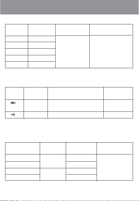
Resistance
Range Resolution Accuracy Overload
Protection
200Ω0.1Ω±(0.8%+5)
2000Ω1Ω250V DC
20kΩ10Ω±(0.8%+2) or AC
200kΩ100Ω
20MΩ10MΩ±(1%+5)
Diodes and Continuity
Range Resolution Remark Overload
Protection
1mV Displays approximate forward
voltage drop: 0.5~0.8V.
250V DC or AC
1ΩBuzzer beeps at ‹70Ω
Temperature
Range Resolution Accuracy Overload
Protection
-40°C~150°C 1°C ±(18%+3)
150°C~1000°C ±(1.5%+15) 250V DC or AC
-40°F~302°F 1°F ±(1%+4)
302°F~1832°F ±(1.5%+15)

300
4
Language page
English . . . . . . . . . . . . . . . . . . . . . . . . . . . . . . . .5-11
Svenska . . . . . . . . . . . . . . . . . . . . . . . . . . . . . .12-17
Norsk . . . . . . . . . . . . . . . . . . . . . . . . . . . . . . . .18-23
Dansk . . . . . . . . . . . . . . . . . . . . . . . . . . . . . . . .24-30
Suomi . . . . . . . . . . . . . . . . . . . . . . . . . . . . . . . .31-36
Deutsch . . . . . . . . . . . . . . . . . . . . . . . . . . . . . . .37-44
Nederlands . . . . . . . . . . . . . . . . . . . . . . . . . . . .45-51
Français . . . . . . . . . . . . . . . . . . . . . . . . . . . . . .52-58
Italiano . . . . . . . . . . . . . . . . . . . . . . . . . . . . . . .59-65
Español . . . . . . . . . . . . . . . . . . . . . . . . . . . . . . .66-72
Português . . . . . . . . . . . . . . . . . . . . . . . . . . . . .73-79
Polska . . . . . . . . . . . . . . . . . . . . . . . . . . . . . . . .80-86
Eesti . . . . . . . . . . . . . . . . . . . . . . . . . . . . . . . . .87-92
Latviski . . . . . . . . . . . . . . . . . . . . . . . . . . . . . .93-100
Lietuvi
Š
kai . . . . . . . . . . . . . . . . . . . . . . . .
101-108
PyÔÔÍËÌ . . . . . . . . . . . . . . . . . . . . . . . . . . . .109-115
Language Contents
Table of contents
Other LIMIT Multimeter manuals


