Southco H3-EM-67-100 User manual


H3-EM-67-100 Electronic Swinghandle
Operating Instructions
J-H3-EM-67-100-M_revE visit www.southco.com for latest version of this document Page 1 of 4
Package Contents
H3-EM-67-x00 Electronic Swinghandle
with Proximity Reader (qty1)
EM-0-45827 M3x25 POZIDRIV®Mounting Screws (qty 4)
EM-0-47151 M3x14 POZIDRIV®Mounting Screw (qty 1)
EM-0-45825 Rotation Limiter (qty 1)
EM-0-58124 Rotation Limiter (qty1)
E5-C-04 Pawl Screw (qty 1)
M3-0-24943-11 Lock Plug Screw (qty 1) (optional)
EM-0-45826 Top Mounting Bracket (qty 1)
EM-0-45822 Bottom Mounting Bracket (qty 1)
Operating Instructions (qty 1)
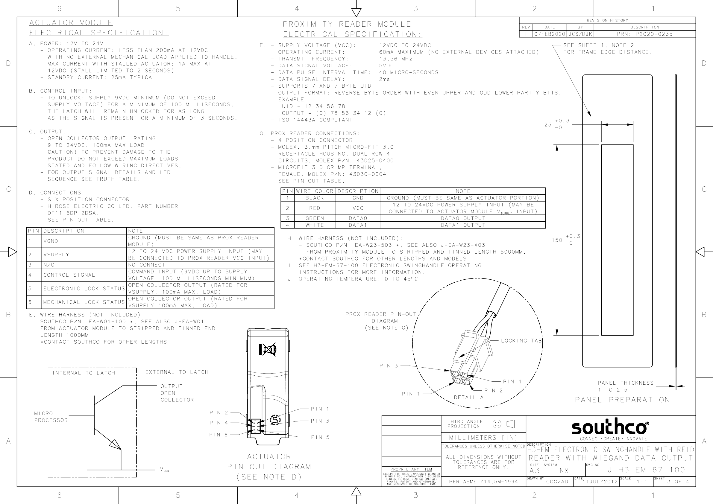
H3-EM-67-x00 Electronic Swinghandle with Proximity Reader
1. Handle
2. Prox Reader
3. Tri-Color Status LED
4. Lock Plug (optional)
Features
Installed 13.56MHz proximity reader module with Wiegand data
output
Compatible with MIFARE® Classic cards with 4 or 7byte Unique
Identifier (UID)
Remote lock and unlock capability
Single or multi-point lock actuation
Momentary or continuous lock actuation
Tri-color LED (blue/magenta/red) to indicate lock and handle
status
DIN lock manual override
Accommodates both left and right doors
For indoor use only
WARNING: The H3-EM-67-000 is shipped without a lockplug. This
product must be paired with a Southco-approved lock to function properly.
Use with an unapproved lockplug voids the product warranty.
Contact Southco for additional support.
Specifications
Actuator Module
Supply Voltage (VSUPPLY): 12VDC to 24VDC (NOTE: Status LED will blink
red if the supply voltage is out of range.)
Standby Current: 50mA maximum at 12VDC
Operating Current: 200mA maximum at 12VDC (with no external
mechanical load applied to handle
Stall Current: 1A maximum (at 12VDC, limited to 2 seconds)
Operating Transit Time: 1 second maximum (NOTE: Power must be
present during transit times. If power is
removed while the lock slide is in transit, it will
complete it’s cycle when power is
restored.)
Electronic Unlock Time: 3 seconds minimum
Open Collector Outputs: Rated for VSUPPLY, 100mA maximum load
Proximity Reader Module
Supply Voltage (VCC): 12VDC to 24VDC
Operating Current: 60mA maximum (no external devices
attached)
Transmit Frequency: 13.56MHz
DATA Signal Voltage: 5VDC
DATA Pulse Interval Time:40µs
DATA Signal Delay: 2ms
Output Format: Reverse Byte Order with Upper and Lower
Parity Bits
Mounting and Installation
Please refer to Southco trade drawing J-H3-EM-67-100 for mounting and
installation details.
NOTE: Use a #1 POZIDRIV®driver when installing the mounting
screws. See Southco trade drawing J-H3-EM-67-100 for additional details.
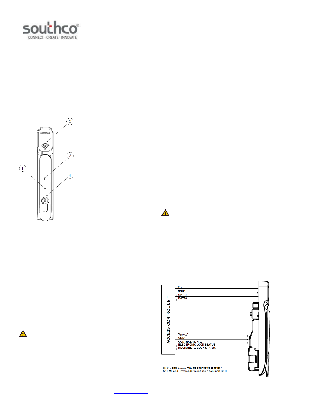
Wiring Diagrams
The H3-EM-67-x00 contains two separate functional modules: the actuator
module and proximity reader module. The actuator module controls and
monitors the locking function of the swinghandle. The proximity module
reads the contents of a compatible proximity card and converts it to
Wiegand format.
These two modules operate independently of each other and require
connection to an access control unit (not provided), as illustrated below,
for the entire product to be fully functional.


