Southworth Powered Dandy PLM 250 User manual

Model# _______________________________
Serial# _______________________________
For equipment manufactured after May 1999.
Powered Dandy Owner’s Manual
PLM 250™
Elevating Powered Helper
September 2016
Southworth Products Corp
P.O. Box 1380/Portland, Maine 04104-1380
Distributed by Ergonomic Partners
Email: [email protected]
Web: www.ergonomicpartners.com
PH: 314-884-8884 | FAX: 800-570-5584

2 PLM 250 — POWERED DANY LIFT
INTRODUCTION
Southworth’s PLM 250 has been designed to take the effort out of lifting and carrying.
The PLM 250 conforms to ergonomic guidelines in order to make them as comfortable
and safe as possible. The battery that powers the platform is sealed for safety and
can be recharged many times.
This manual contains information to acquaint you with the safe, proper use and
upkeep of the PLM 250. You should ensure that this manual is available to personnel
working with the PLM 250.
In the interest of safety please read the entire manual carefully and be familiar with
its contents before you use or service the PLM 250. If you have any questions about
any instructions in this manual, please contact your dealer or Southworth Products
Corporation.
The PLM 250 is tted with an identication plate located on the central cross member
at the base of the actuator. The identication plate is stamped with the model number,
capacity and serial number; this information should be provided when seeking spare
part inquiries or technical support.

PLM 250 — POWERED DANDY LIFT 3
TABLE OF CONTENTS
INTRODUCTION.............................................................................................................................................. 2
RESPONSIBILITY OF OWNERS AND USERS ............................................................................................... 4
SAFETY ALERT SYMBOLS AND SIGNAL WORDS........................................................................................ 5
UNPACKING ................................................................................................................................................... 6
Transit Damage .......................................................................................................................... 6
Hazardous Environments............................................................................................................ 6
High Cycle Applications .............................................................................................................. 6
SPECIFICATIONS............................................................................................................................................ 6
PARTS BREAK DOWN .................................................................................................................................... 6
OPERATION 6
Platform Control.......................................................................................................................... 6
Caster Conguration................................................................................................................... 6
Brake........................................................................................................................................... 6
Direction Lock ............................................................................................................................. 6
Battery......................................................................................................................................... 6
BATTERY LIFE................................................................................................................................................. 7
CONTROL BOX ............................................................................................................................................... 7
ACTUATOR 7
LOAD CAPACITY ............................................................................................................................................. 8
MAINTENANCE ............................................................................................................................................... 8
Monthly ....................................................................................................................................... 9
Annually ...................................................................................................................................... 9
TROUBLE SHOOTING .................................................................................................................................... 9
ORDERING REPLACEMENT PARTS............................................................................................................ 10
RETURN MATERIALS AUTHORIZATION (RMA) ...........................................................................................11
WARRANTY 12
LIST OF FIGURES
Figure 1 PLM 250...................................................................................................................................... 7
Figure 2 Pinch Points................................................................................................................................ 7
Figure 3 Battery Pack & Control Box ........................................................................................................ 8
Figure 4 Labels and Precautionary Markings............................................................................................ 9

4 PLM 250 — POWERED DANY LIFT
Responsibility of Owners and Users
Inspection and Maintenance
The device shall be inspected and maintained in proper working order in accordance with
Southworth’s owner’s manual.
Removal from Service
Any device not in safe operating condition such as, but not limited to, excessive leakage,
missing rollers, pins, or fasteners, any bent or cracked structural members, cut or frayed
electric, hydraulic, or pneumatic lines, damaged or malfunctioning controls or safety de-
vices, etc. shall be removed from service until it is repaired to the original manufacturer’s
standards.
Deection
It is the responsibility of the user/purchaser to advise the manufacturer where deection
may be critical to the application.
Repairs
All repairs shall be made by qualied personnel in conformance with Southworth’s instruc-
tions.
Operators
Only trained personnel and authorized personnel shall be permitted to operate the equip-
ment.
Before Operation
Before using the device, the operator shall have:
•Read and/or had explained, and understood, the manufacturer’s operating instruc-
tions and safety rules.
•Inspected the device for proper operation and condition. Any suspect item shall be
carefully examined and a determination made by a qualied person as to whether
it constitutes a hazard. All items not in conformance with Southworth’s specication
shall be corrected before further use of the equipment.
During Operation
The device shall only be used in accordance with this owner’s manual.
•Do not overload.
•Ensure that all safety devices are operational and in place.
Modications or Alterations
Modications or alterations to any Southworth industrial positioning equipment shall be
made only with written permission from Southworth.

PLM 250 — POWERED DANDY LIFT 5
SAFETY ALERT SYMBOLS AND SIGNAL WORDS
The safety of all persons operating, maintaining, repairing, or in the vicinity of this equipment is of paramount concern. This is
a powerful machine with moving parts, and is capable of causing personal injury if proper precautions are not taken. Therefore,
throughout this manual, certain hazards have been identied which may occur in the use of the machine, and there are appro-
priate instructions or precautions which should be taken to avoid these hazards. In some cases, there are consequences which
may occur if instructions or precautions are not followed. Below are the symbols and signal words along with their denitions
referenced from ANSI Z535.4 - Product Safety Signs and Labels.
Safety Alert Symbols
These are the safety alert symbols.. They are used to alert you to potential physical injury hazards. Obey all
safety messages that follow this symbol to avoid possible injury or death.
For use with DANGER signal word
(Red Background)
For use with WARNING signal word
(Orange Background)
For use with CAUTION signal word
(Yellow Background)
Signal Words
The meaning of different signal words as dened by ANSI Standard Z535.4 indicates the relative seriousness
of the hazardous situation.
DANGER indicates a hazardous situation which, if
not avoided, will result in death or serious injury.
WARNING indicates a hazardous situation which, if
not avoided, could result in death or serious injury.
CAUTION, used with the safety alert symbol, indi-
cates a hazardous situation which, if not avoided,
could result in minor or moderate injury.
NOTICE is used to address practices not related
to personal injury.
(Red Background)
(Orange Background)
(Yellow Background)
(Blue Background)
SAFETY
INSTRUCTIONS
SAFETY INSTRUCTIONS (or equivalent) signs
indicate safety-related instructions or procedures.
(Green Background)

6 PLM 250 — POWERED DANY LIFT
UNPACKING AND
SET-UP OF THE
PLM 250
HIGH CYCLE APPLICATIONS
The PLM 250 is designed for intermittent use.
For high cycle operations, the following
should be observed:
1) The PLM 250 is designed to achieve a
minimum life of approximately 10,000
cycles. For intermittent use, this
equates to many years of service.
2) The PLM 250 linear actuator should
not exceed six (6) full cycles per hour.
The recommended duty cycle for the
actuator motor is 10%. This means that
the motor should not be operated for
more than 6 minutes of every hour.
OPERATING
THE PLM 250
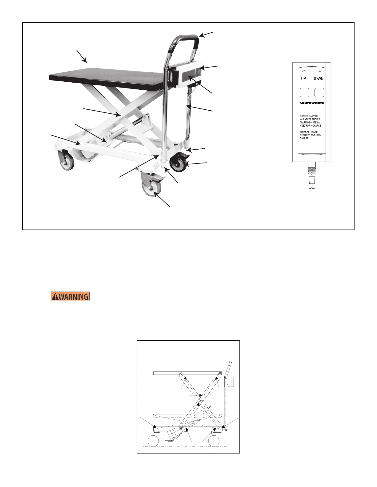
PLATFORM CONTROL
The position of the platform is controlled
with a push button switch located on the
hand control. The PLM 250 can be raised
by pressing the UP button on the switch or
lowered by pressing the DOWN button on
the switch.
WARNING!
As the PLM 250 platform moves
up and down, “pinch points” are
created where the scissor legs
cross, where the legs meet the
base and platform and in the
path on which the rollers travel.
When operating the PLM 250,
be careful to ensure that nobody
1) Cut the banding straps and remove the
PLM 250 from the box. (Make sure all
of the parts are included before the box
is discarded. Figure 1.)
2) Attach the handle to the PLM 250 by
sliding the two threaded ends of the
handle into the pockets that are welded
to the base frame. Using the lock
washers and the nuts, secure rmly.
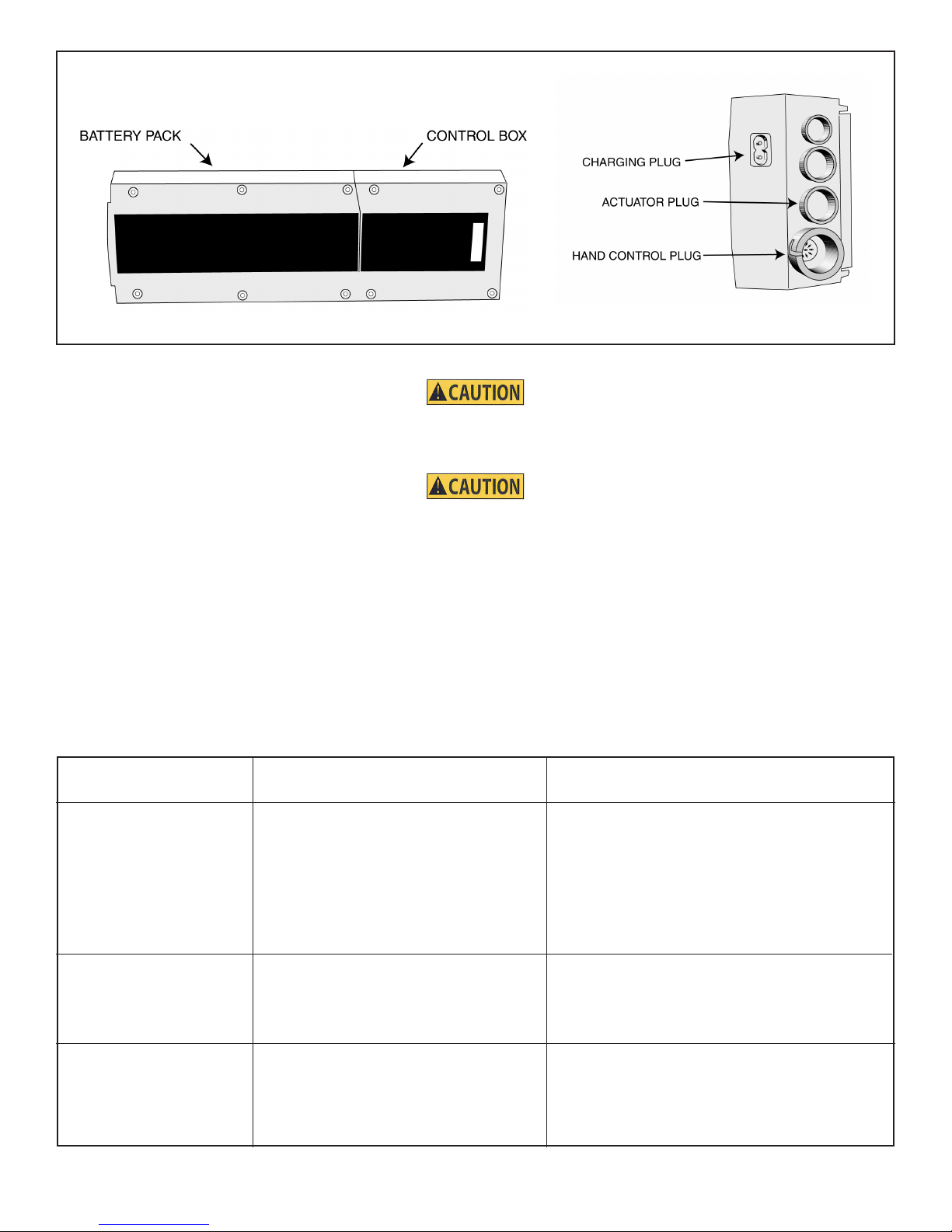
3) Locate the battery control box assembly.
Attach the assembly to the handle using
the 4 self tapping screws, making sure
the control box is to the right and
the battery box is to the left. This
allows the actuator to plug into the
control box.
4) Makeall thecorrect electricalconnections
(gure 3).
TRANSIT DAMAGE
Inspect the PLM 250 for signs of damage
in transit, paying particular attention to
the electrical cabling and connections. If
there is evidence of damage, contact your
Southworth dealer before using the PLM
250.
HAZARDOUS
ENVIRONMENTS
The PLM 250’s electrical equipment is not
suitable for use in ammable or explosive
environments and must never be used
when such hazards exist.
SPECIFICATIONS
Capacity 500 lbs
Platform Size 19-5/8” x 31-1/2”
Lowered Height 14-1/4”
Raised Height 32-1/2”
Vertical Travel 19”
Weight 20 lbs
Dimensions (L x H x W) 38” x 37” x 19-5/8”
Casters 5”
Rise Time 36 Seconds
PARTS BREAK DOWN
PARTS Part #
Platform & Frame 3060649
Directional Caster 5905969
Brake Caster 5905970
Front Caster 5905968
Battery Pack 5905918
Battery Mounting Bracket 5905920
Control Box 5905917
Hand Control 5905958
Actuator 5905916
Decal Kit 3055607
becomes caught in the moving
parts. (Figure 2)
CASTER CONFIGURATION
The PLM 250 is supplied with four swiveling
casters. One of the rear casters is tted
with a brake and the other rear caster has
a direction lock.
BRAKE
The brake prevents the caster from both
swiveling and rolling. Press the lever
located on the top of the caster to engage
the brake.
CAUTION!
The brake is an important safety
device. Please ensure it is
engaged when the PLM 250 is
unattended. Attempt to nd level
ground whenever possible.
DIRECTION LOCK
The direction lock prevents the caster from
swiveling but allows the caster to roll as
usual. Use it when pushing the PLM 250
in a straight line to provide greater stability.
BATTERY
The PLM 250 is supplied with a 24 volt
battery pack which snaps easily on to
the control box. This allows for a quick
exchange of battery packs if needed. The
control box is mounted to the handle of the
PLM 250 for easy access. The control box
PLM 250 — POWERED DANDY LIFT 7
Figure 1. PLM 250
Hand Control
Platform and Frame
Handle
Battery Pack
Control Box
Bottom Pivot
Direction Lock Caster
Brake Caster
Power Lead
Actuator
Center Pivot
Rollers
Lockwasher and Nut
Lockwasher and Nut
includes a quick disconnect hand control,
and an internal charger.
The battery is a VRLA sealed lead acid
battery. It is exempted from DOT Hazardous
Material. VRLA batteries can be shipped by
traditional carriers such as UPS or FEDEX.
WARNING!
The battery contains lead acid and should
not be punctured or damaged. Seek
urgent medical advice if acid contacts
skin or clothing. Ensure that the battery
is disposed of safely and according to
local regulations.
BATTERY LIFE
Because of the batteries self-discharge, over time you
can not expect the battery to be fully charged. When
you receiveyourPLM 250 it is recommended that
you charge the battery immediately. The initial
charge needs to be for a minimum of 24 to 48
hours. After this rst initial charging, there is a
maximum charging time of 6 hours to reach the
batteries full charge capacity.
The life of the battery is determined on the
amount of usage between charging. This is
best explained as follows:
• 100% discharging depth: If the
battery is totally discharged, there is
approximately 180 charging cycles
available.
• 50% discharging depth: If the battery is
50% discharged, there is approximately
400 charging cycles available.
• 30% discharging depth: If the battery is
30% discharged, there is approximately
1200 charging cycles available.
Therefore it is recommended to recharge
the battery as frequently as possible.
Doing this will ensure the longest battery
life available.
CONTROL BOX
Your control box is equipped with some
special features. It has an internal charger
with a 10 ft. charging cord, a soft start and
stop function which eliminates jumping of
the actuator and table. There is a unique
acoustic alarm feature that tells you when
the battery is at 50% capacity. The hand
control, which is clearly marked with UP and
DOWN buttons, comes with a 24” coil cord.
ACTUATOR
The PLM 250’s actuator is one of its best
features. You can hardly tell it’s running
because of its low noise level that’s below
45db. It has built-in end-stop switches
for protection against dead heading or
damaging the actuator. The operating
mechanism is a simple screw jack that’s
driven by an internal DC motor.
Figure 2. PLM 250 Pinch Points
8 PLM 250 — POWERED DANY LIFT
LOAD CAPACITY
The load capacity is stamped into the
identication plate located on the central
cross-member, at the base of the actuator
and capacity stickers on either side of the
table. (figure 4) The PLM 250 contains
an overload protection device that may
cut power to the unit if overloaded. If this
occurs, make sure that the PLM 250 is not
loaded beyond its capacity. The device will
reset within a matter of seconds and power
will be restored. The load capacity is based
on the load applied centrally and uniformly
to the platform.
CAUTION!
Do not overload the PLM 250, as
this may damage the unit.
CAUTION!
Do not let loads significantly
overhang the platform, as this
could result in the platform being
overloaded, and cause the PLM
250 to tip over.
MAINTENANCE
The PLM 250 requires minimal maintenance.
The PLM 250 is designed for a life of
approximately 10,000 cycles after which a
new actuator may be required.
Daily inspection: Make sure there are no
foreign objects in the way of the rollers and
the scissor legs. Make sure all wires are
plugged into the control box.
Figure 3. Battery Pack and Control Box
PROBLEM
PLM 250 will not raise.
PLM 250 is slow to raise or
will not raise to the top.
PLM 250 will not lower.
POSSIBLE CAUSES
1) Power is not supplied to the actuator.
2) Batteries are discharged.
3) An electrical fault may exist or the
actuator may have burned out.
1) Batteries are discharged.
2) A fault may exist with the motor/switch.
1) Power is not supplied to the actuator.
2) Batteries are discharged.
REMEDY
Check whether the power cable is plugged in.
Recharge the batteries.
Contact Southworth Customer Service Dept. 1-800-
743-1000.
Recharge the batteries.
Contact Southworth Service Dept. 1-800-743-1000.
Check whether the power cable is plugged in.
Recharge the batteries.
Quick Check Troubleshooting Chart
PLM 250 — POWERED DANDY LIFT 9
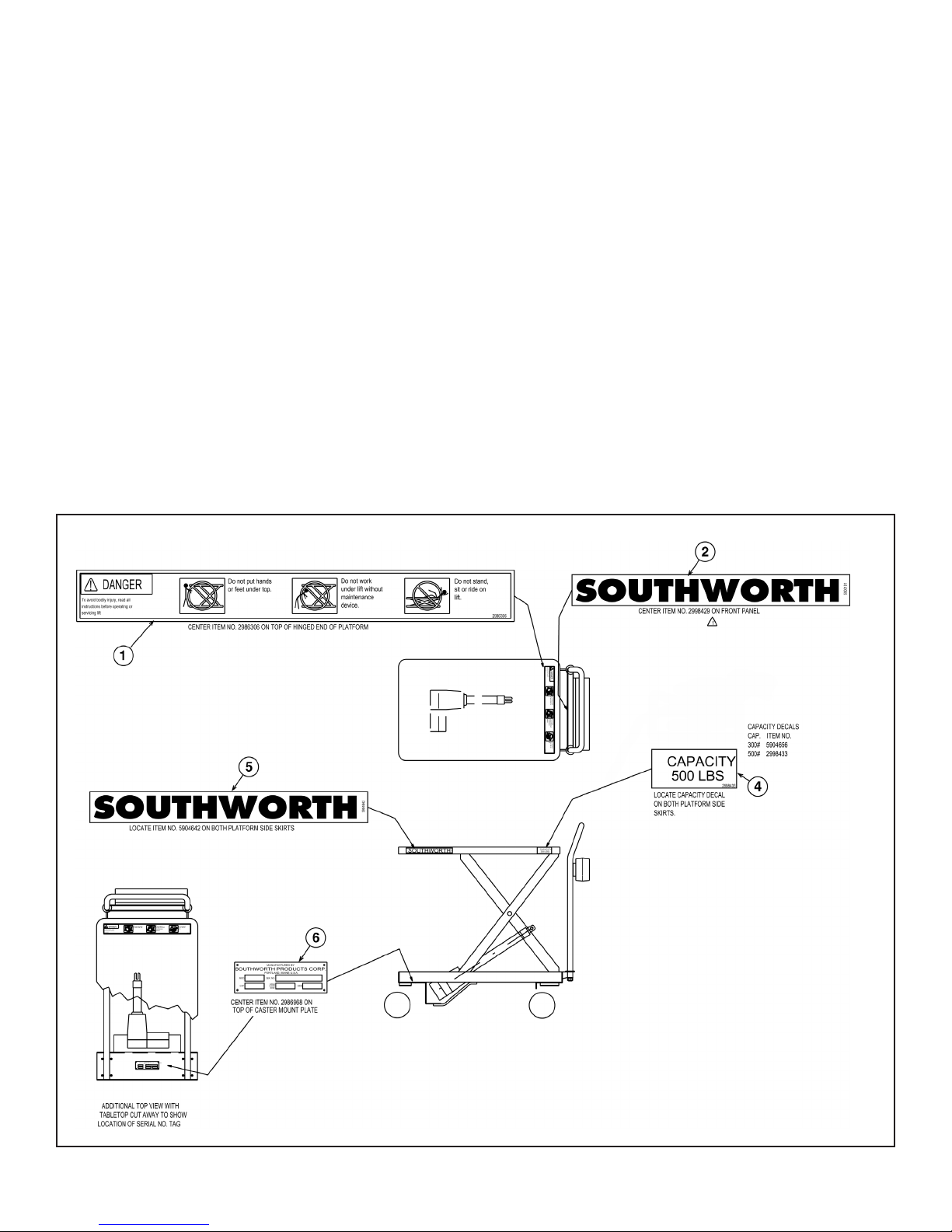
Figure 4. Labels and Precautionary Markings
LABELS AND
PRECAUTIONARY
MARKINGS
#1 2986306 – Danger
#2 2998429 – SOUTHWORTH
#4 2998433 – 500 lb Capacity
#5 5904642 – SOUTHWORTH
#6 2986968 – Name Plate
MONTHLY MAINTENANCE
1) Check all welds, making sure they are
intact, no cracks or broken spots.
2) Turn the PLM 250 on its side and check
that the caster bolts are tight. If the
caster with the direction lock requires
tightening, engage the direction lock
and ensure that the castor is pointing
straight ahead before tightening.
3) Check that the cotter pins on the
actuator pivot bolts are in place.
4) Inspect the cable and plug for signs of
damage.
5) Inspect the battery control box
assembly for obvious signs of abuse.
6) Use a clean rag to wipe the paths along
which the rollers travel.
7) Lubricate (WD-40) pivots and roller
pins.
ANNUALLY OR 3000 CYCLES
1) Dismantle.
2) Lubricate (WD-40) pivots and roller
pins.
3) Clean.
4) Reassemble.
TROUBLE
SHOOTING
The PLM 250 should provide years of
trouble-free service. However, in the event
you experience difculties with the PLM
250, the troubleshooting chart on page 8
may help you identify the problem.
You may, of course, contact Southworth’s
Customer Service Dept. at 1-800-743-1000.

10 PLM 250 — POWERED DANY LIFT
Ordering Replacement Parts
Southworth has carefully chosen the components in your unit to be the best available for the purpose.
Replacement parts should be identical to the original equipment. Southworth will not be responsible
for equipment failures resulting from the use of incorrect replacement parts or from unauthorized
modications to the machine.
Southworth will gladly supply you with replacement parts for your Southworth lift. With your order,
please include the model number and the serial number of the unit. You will nd these numbers on
the name plate.
To order replacement parts, please call the Parts Department at (207) 878-0700. Parts are shipped
subject to the following terms:
• FOB factory.
• Returns only with the approval of our parts department.
• Payment net 30 days (except parts covered by warranty).
• Freight collect (except parts covered by warranty).
• The warranty for repair parts is 30 days from date of shipment.
Parts replaced under warranty are on a “charge-credit” basis. We will invoice you when we ship the
replacement part, then credit you when you return the assumed substandard part, and we verify that
it is covered by our warranty. Labor is not covered under warranty for Parts orders.
Parts Department
Southworth Products Corp
P.O. Box 1380
Portland, ME 04104-1380
Distributed by Ergonomic Partners
Email: [email protected]
Web: www.ergonomicpartners.com
PH: 314-884-8884 | FAX: 800-570-5584

PLM 250 — POWERED DANDY LIFT 11
RETURN MATERIALS AUTHORIZATION
(RMA) PROCEDURES
The Southworth Return Authorization (RMA) Procedure is provided as a courtesy to our custom-
ers in the event a product or a component may need to be returned.
If a customer wishes to return a Southworth product, the rst step in the process is to request an
RMA number from the Customer Service Department. This request must be made on or before
the thirtieth (30th) calendar day following the date of Southworth’s invoice for the merchandise
being returned.
The RMA number must appear on the outside of any packaging material for a return to be
accepted and processed at Southworth manufacturing facility. Customers shipping returns back
to Southworth, from the continental US, Canada or Mexico have thirty (30) days from the effec-
tive date of the RMA to have the merchandise arrive freight prepaid at Southworth. If the RMA
number is missing or expired (beyond 30 days) it may be refused at Southworth. If any RMA is
expired, contact the Customer Service Department before returning to Southworth.
All RMA’s are subject to the appropriate restocking fees. All credits issued are less restocking
fees as applicable, plus any assessed outbound/inbound in-transit damages.
Return addresses: please refer to your RMA for the specic address to which your product
should be returned. Southworth has multiple facilities and returning goods to other than the des-
ignated location will result in goods being refused.
Please contact the Customer Service Department at anytime regarding questions to this proce-
dure.
Southworth Products Corp
P.O. Box 1380
Portland, ME 04104-1380
Distributed by Ergonomic Partners
Email: [email protected]
Web: www.ergonomicpartners.com
PH: 314-884-8884 | FAX: 800-570-5584

12 PLM 250 — POWERED DANY LIFT
Southworth Products Corp warrants this product to be free from defects in material or
workmanship for a period of 1 year of single shift usage from date of shipment, providing
claim is made in writing within that time period. This warranty shall not cover modied
designs for special applications, failure or defective operation caused by misuse,
misapplication, negligence or accident, exceeding recommended capacities, failure to
perform required maintenance or altering or repairing, unless alteration is authorized by
Southworth Products Corp. Except as set forth herein, there are no other warranties,
express or implied, including the warranties of merchantability and tness for a particular
purpose, all of which are hereby excluded.
Southworth Products Corp makes no warranty or representation with respect to the com-
pliance of any product with state or local safety or product standard codes, and any failure
to comply with such codes shall not be considered a defect of material or workmanship
under this warranty. Southworth Products Corp shall not be liable for any direct or conse-
quential damages arising out of such noncompliance.
Southworth Products Corp’s obligation under this warranty is limited to the replacement or
repair of defective components at its factory or another location at Southworth Products
Corp’s discretion. The Southworth Warranty is for product sold with in North America. For
products shipped outside of North America the warranty will be for replacement of defec-
tive parts only. Labor is not included. This is buyer’s sole remedy. Except as stated herein,
Southworth Products Corp will not be liable for any loss, injury or damage to persons or
property, nor for direct, indirect, or consequential damage of any kind, resulting from fail-
ure or defective operation of said product.
This warranty may be altered only in writing by Southworth Products Corp, Portland,
Maine.
SOUTHWORTH PRODUCTS CORP
P.O. Box 1380, Portland, ME 04104-1380
Distributed by Ergonomic Partners
Email: [email protected]
Web: www.ergonomicpartners.com
PH: 314-884-8884 | FAX: 800-570-5584
1 YEAR WARRANTY
Table of contents
Popular Outdoor Cart manuals by other brands


Combi
Combi ANGEL WAGON AW Series Instruction Manual and Inspection Manual

Granite
Granite 97011-4 owner's manual

Oklahoma Sound
Oklahoma Sound MULTI MEDIA CART MMC Product handbook

Rolly Toys
Rolly Toys Double Tyre manual

KitchenAid
KitchenAid KFFU271TSS00 parts list

Great Little Trading
Great Little Trading Time for Tea Trolley quick start guide


