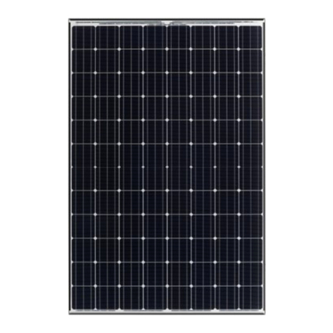
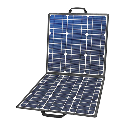
SOVA SOLAR SS35572MC Operating instructions

INSTALLATION & SERVICE INSTRUCTIONS
MANUAL FOR SOLAR PV MODULE
www.sovasolar.com
READ THIS MANUAL BEFORE USING SOVA SOLAR PRODUCTS.
FAILURE TO FOLLOW THE MANUAL MAY RESULT IN SERIOUS INJURY/DAMAGE.
“Preserve the manual for long use”
DISCLAIMER OF LIABILITY
This manual describes the installation, operation and maintenance of the solar photovoltaic module.
The installation, handling and use of Sova Solar crystalline modules are beyond company control. Sova Solar
does not assume any responsibility for loss, damage, injury or expense resulting from the improper
installation, handling, use or maintenance.
Sova Solar assumes no responsibility for any infringement of patents or other rights of third parties that
may result from use of the module. No license is granted by implication or under any patent or patent rights.
Specifications included in this manual are subject to change without prior notice.
SAFETY
Follow the general and national safety and accident prevention regulations.
Instructions relating to the functional safety of the system are in bold type.
Do not connect any defective or damaged equipment (including measurement equipment) to PV
modules.
Follow the charging instructions of the battery manufacturer.
Check the charging process regularly as described by the charger manufacturer.
Never alter or remove the factory plates and identification labels.
Keep children away from PV systems.
Do not use water to extinguish fires of an electrical origin.
Do not walk on the modules.
The warnings, precautions and instruction discussed in this manual cannot cover all possible
conditions and situations that may occur. The module should be used with common sense and
caution by the end user.
INSTALLATION WARNING
DANGER OF EXPLOSION FROM SPARKING! DANGER OF ELECTRIC SHOCK!
Solar modules generate electricity under incident light. The open circuit high voltage is present, even when
the incident light levels are low. So it is recommended that the connection to the charge controller, load and
battery may only be connected by trained personnel and i accordance with the applicable regulations.

INSTALLATION & SERVICE INSTRUCTIONS
MANUAL FOR SOLAR PV MODULE
www.sovasolar.com
FOLLOW THE INSTALLATION AND OPERATING INSTRUCTIONS FOR PV MODULE AND ALSO FOR ALL
COMPONENTS OF THE PV SYSTEM.
Protect the solar modules from incident light during installation, e.g. cover them.
Never touch un-insulated cable ends.
Use only insulated tools.
Handle solar module with care, edges may be sharp.
Module must be connected using UL listed outdoor rated wire of the correct thickness for the
amperage rating and length.
As thumb rule, maximum voltage drop in the loop should be 3%.
Ensure that no cables are damaged.
Verify that installation surface has no hidden obstacles.
At a voltage of > 75 V, particularly with regard to module open circuit voltage (over the entire
temperature range), the entire solar energy system must be installed with protection class Il as per
IEC 61730.
Select appropriate charge controller and battery for the solar module.
Secure all connections using terminals, or solder all wire splices to ensure good connection.
Ensure that all loads to be connected are switched off. If necessary, remove the fuse.
UNPACKING AND STORAGE
At time of receipt, verify that the product delivered is in fact the product ordered.
Leave the product in its original packing box until you are ready to install.
Store packing boxes in a clean, dry area with relative humidity below 85% and ambient
temperatures between -20°C and 50°C.
Do not stack more than the 2 Boxes (Pallets) of each other.

INSTALLATION & SERVICE INSTRUCTIONS
MANUAL FOR SOLAR PV MODULE
www.sovasolar.com
At the installation site, take care to keep modules and particular their electrical contacts clean and
dry before installation. If connector cables are left in damp conditions then the contacts may corrode.
Any module with corroded contacts should not be used.
If pallets are stored temporarily outside then place a protective covering over the pallet to protect it
from direct weathering and do not stack more than 1 pallet high.
Two people are required to unpack the modules from the packing box, when handling modules
always use both hands.
Protect the module edges for temporary storage outside the pallet.
Do not use a knife to cut the zip-ties, but use wire cutting pliers.
Do not place modules directly on top of each other.
CLIMATE CONDITION
Install the SOVA SOLAR Photovoltaic modules in the following conditions: Operating temperature: -
40°C to +85°C.
Storage temperature: -40°C to +50°C.
Humidity: below 85RH%.
Wind pressure: below 2400Pa. (speed 130km/h for 1hr)
Snow Load Pressure: below 5400Pa.
Corrosion resistance: except for corrosive salt area and sulfurous area.
MOUNTING
Before installing your system, contact local authorities to determine the necessary permit,
installation and inspection requirements.
Mounting location for solar module must be facing SUN and not be blocked by shadows. It is
recommended to tilt to horizon equal to the latitude of the location for annual optimized power
generation.
Do not install PV modules in a location where they will be immersed in water or continually exposed
to water from a sprinkler or fountain, etc.
Avoid using a mounting method that will block the drainage holes in the module frame.

INSTALLATION & SERVICE INSTRUCTIONS
MANUAL FOR SOLAR PV MODULE
www.sovasolar.com
Panels are not subjected to wind or snow loads exceeding the maximum permissible loads, and are
not subject to excessive forces due to the thermal expansion of the support structures.
The minimum mechanical means is to be used for securement of the module or panel to the roof as
per the instructions below, For a non-integral module or panel, the assembly is to be mounted over
a fire resistant roof covering rated for the application
Structure must be strong enough to support the weight of the solar module and wind load. Mounting
system consists of corrosion-proof bolts and nuts through the mounting holes in the mounting frame.
Mounting holes details for all modules are given in table below-
Model
Range(Polycrystalline)
Model Range
(MONO PERC)
Module
Dimension(mm)
Mounting
hole (Oblong-
mm)
Vertical(mm)
Horizontal(mm)
SS29572MC - SS35572MC
SS33072MP - SS40072MP
1961 x 991 x 40
8 x 10
978
943
SS28066MC - SS34066MC
SS30566MP - SS36566MP
1802 x 991 x 40
8 x 10
901
943
SS26060MC - SS31060MC
SS28060MP - SS34060MP
1646 x 991 x 40
8 x 10
820
943
SS23054MC - SS28054MC
SS25054MP - SS30054MP
1485 x 991 x 40
8 x 10
743
943
SS21048MC - SS25048MC
SS22548MP - SS26548MP
1326 x 991 x 40
8 x 10
663
943
SS16036MC - SS19036MC
SS17036MP - SS20036MP
1008 X 991 X 40
8 x 10
504
943

INSTALLATION & SERVICE INSTRUCTIONS
MANUAL FOR SOLAR PV MODULE
www.sovasolar.com
SERIES / PARALLEL CONNECTIONS
Modules can be wired in series to increase voltage. Connect wires from positive terminal of one module to
the negative terminal of the next module. All modules connected in series should be of the same model
number and/or type. Make sure the number of modules connected in series does not exceed: ((Maximum
system voltage / Open circuit voltage of the module) —1) at standard condition, AM1.5G, 25 degrees
temperature, 1,000 W/m2.Connect modules in parallel to increase current. Connect wires from the positive
terminal of the one module to the positive terminal of the next module. Do not connect modules in parallel
without using a connection box. The number of parallel strings depends on the system integrator’s
requirements and the inverter ratings.
This can be done using the formula below,
Max System voltage = X * Voc * [1 + ((Tα-Voc (%) x (25 - Tmin))] Where
X - No: modules which are connected in series.
Voc - Open circuit voltage of each module (Refer to the Data Sheet)
Tα-Voc - Thermal coefficient of open circuit voltage for the module in Percentage (refer to Sova
Solar Spec sheet)
Tmin - Minimum ambient temperature of the location of the plant
GROUNDING
Module frames should be connected to an earth ground for safety and protection from lightning. The array
frame shall be grounded in accordance with NEC Article 250 (USA) or CEC in Canada. A good connection
between the grounding hardware is essential for an effective ground. The anodization on a module frame
provides a coating to minimize the corrosion due to weather and it acts as a barrier that reduces the
effectiveness of the grounding connection. For an adequate ground, the grounding hardware should pierce
the anodization layer.
1. Stainless steel Bolt -304 with hexagonal and cheese head
Bolt Size: 8 —32 (As per ASME standard chart)
In Metric standard: M4 x 16 mm lon engage thread is
13.5 mm with the frame (2.5 mm frame thickness and
16mm length of the screw)
2. Stainless Steel Cupped Washer —M4 Stainless steel 304.
3. Stainless Steel Flat Washer —M4 Stainless steel 304.
4. Tar Washer —M4 Stainless steel 304
5. Stainless Steel Nut —M4 stainless steel 304.

INSTALLATION & SERVICE INSTRUCTIONS
MANUAL FOR SOLAR PV MODULE
www.sovasolar.com
ROOF MOUNTING
Clearance between the module frame and the mounting surface is required to allow cooling air to
circulate around the back of the module. This also allows any condensation or moisture to dissipate.
The module should never be sealed to the mounting surface with sealant that prevents air from
circulating under the module.
Leave 4 inches of clearance between the roof and the module frame.
Refer to your local authority for guidelines and requirements for building or structural fire safety.
For roof application, the modules should be mounted over a fire resistant covering rated for the
application
Sova Solar PV Modules have a Class C fire resistance rating in accordance with IEC 61730
certification. The fire rating of this module is valid only when mounted in the manner specified in
the Mechanical mounting instructions. Rooftop installations should be placed over fire resistant roof
Coverings only. Roof constructions and installations may affect the fire safety of a building; improper
installation may create hazards in the event of a fire.
Under normal conditions, a photovoltaic module is likely to experience conditions that produce
more current and/or voltage than reported at Standard Test Conditions. Accordingly, the values of
Isc and Voc marked on this module should be multiplied by a factor of 1.25 when determining
component voltage ratings, conductor capacities, fuse sizes, and size of controls connected to the PV
output.
Do not drill through the Aluminium frame. You may damage the frame or break the glass.
ELECTRICAL PARAMETERS
The tolerance of Voltage and Current within ±3% for grid and ±5% for battery charging.
For Multi Crystalline Modules-
Temperature coefficient for Voc/°C is -0.25%
Temperature coefficient power/°C is -0.277%
MODULE WIRING
Refer to section 690-8 of the National Electric Code (NEC) for an additional multiplying factor of
125% (80% de-rating) which may be applicable.
Conductor recommendations: Stranded copper cables with a cross sectional area of 4mm² which are
rated for 1000VDC/ 1500VDC, 90°C and are UV resistant.( For TSM-PE05A.**, PE14A.**, 1500 V DC,
90°C and are UV resistant) All other cables used to connect the DC system should have a similar (or
better) specification .
Artificially concentrated sunlight shall not be directed on the module or panel.

INSTALLATION & SERVICE INSTRUCTIONS
MANUAL FOR SOLAR PV MODULE
www.sovasolar.com
FUSING
When fuses are fitted they should be rated for the maximum DC voltage and connected in each, non-
grounded pole of the array (i.e. if the system is not grounded then fuses should be connected in both
the positive and negative poles).
The maximum rating of a fuse connected in series with an array string is typically 15A but the actual
module specific rating can be found on the product label and in the product datasheet.
This fuse rating value also corresponds to the maximum reverse current that a module can
withstand (when one string is shaded then the other parallel strings of modules will be loaded by the
shaded string and current will flow) and therefore impacts the number of strings in parallel.
Bypass Diode qty. in Junction Box: 3nos –Model no: GF3045
TYPE OF PRODUCT APPLICATION
“The modules are qualified for application class A: Hazardous voltage (IEC61730: higher than 50V DC;
EN61730: higher than 120V), hazardous power applications (higher than 240W) where general contract
access is anticipated (Modules qualified for safety through EN IEC61730-1 and EN IEC61730- 2 within this
application class are considered to meet the requirements for Safety class Il).
SERVICING
Before service and maintenance or cleaning follow these to prevent from electric shock:
Wear electrically insulated gloves.
Cover the solar module with blanket or any dense cover.
Disconnect module connection to the battery and load and then check the module and mounting
system.
Clean with mild, non-rough cleanser and soft cloth then dry and inspect the solar module system
every after 15days to get optimum output. The frequency may vary depending on the dust pollutant
level in your surroundings.

INSTALLATION & SERVICE INSTRUCTIONS
MANUAL FOR SOLAR PV MODULE
www.sovasolar.com
PRODUCT TEST & LIMITED WARRANTY
Product certified by IS 14286 and IS 61730-1 & 2. Test conducted such as wind speed, mechanical load,
damp-heat, reverse current high voltage test etc.
Upto 20watt: Manufacturing defect: 2years. Rated power: 8 years to 90%:10years to 80%.
Above 20watt: Manufacturing defect: 5years. Rated power: 12 years to 90%: 25years to 80%.
TECHNICAL DATA SHEET
Model Name
System
Voltage
(V)
Electrical Ratings (Polycrystalline Module)
Fuse
rating (A)
Module
weight (Kg)
Voc (V)
Vm (V)
Isc (A)
Im (A)
Pm (W)
FF
Eff (%)
72 Cells
SS35572MC
1500
46.77
37.69
9.73
9.42
355
78%
18.27
20
21.3
SS35072MC
1500
46.68
37.53
9.62
9.33
350
78%
18.01
20
21.3
SS34572MC
1500
46.60
37.25
9.56
9.27
345
78%
17.75
20
21.3
SS34072MC
1500
46.56
37.01
9.48
9.20
340
77%
17.50
20
21.3
SS33572MC
1500
46.42
36.87
9.41
9.10
335
77%
17.24
20
21.3
SS33072MC
1500
46.31
36.77
9.30
8.98
330
77%
16.98
20
21.3
SS32572MC
1500
46.15
36.68
9.21
8.87
325
77%
16.72
20
21.3
SS32072MC
1500
45.92
36.58
9.12
8.76
320
77%
16.47
20
21.3
SS31572MC
1500
45.69
36.45
9.08
8.65
315
76%
16.21
20
21.3
SS31072MC
1500
45.46
36.32
8.94
8.54
310
76%
15.95
20
21.3
SS30572MC
1500
45.23
36.22
8.85
8.43
305
76%
15.69
20
21.3
SS30072MC
1500
45.00
36.11
8.76
8.31
300
76%
15.44
20
21.3
SS29572MC
1500
44.77
36.05
8.67
8.19
295
76%
15.18
20
21.3
66 cells
SS34066MC
1500
43.76
34.85
9.95
9.76
340
78%
19.04
20
19.6
SS33566MC
1500
43.43
34.74
9.90
9.65
335
78%
18.76
20
19.6
SS33066MC
1500
43.22
34.47
9.79
9.58
330
78%
18.48
20
19.6
SS32566MC
1500
42.99
34.37
9.68
9.46
325
78%
18.20
20
19.6
SS32066MC
1500
42.77
34.27
9.57
9.34
320
78%
17.92
20
19.6
SS31566MC
1500
42.64
34.19
9.54
9.22
315
78%
17.64
20
19.6
SS31066MC
1500
42.50
34.08
9.40
9.10
310
78%
17.36
20
19.6
SS30566MC
1500
42.45
33.93
9.29
8.99
305
77%
17.08
20
19.6
SS30066MC
1500
42.30
33.84
9.20
8.87
300
77%
16.80
20
19.6
SS29566MC
1500
42.12
33.72
9.10
8.75
295
77%
16.52
20
19.6
SS29066MC
1500
41.93
33.61
8.96
8.63
290
77%
16.24
20
19.6
SS28566MC
1500
41.82
33.50
8.82
8.51
285
77%
15.96
20
19.6
SS28066MC
1500
41.73
33.39
8.68
8.39
280
77%
15.68
20
19.6
60 cells
SS31060MC
1500
39.78
31.76
9.95
9.77
310
78%
19.00
20
18
SS30560MC
1500
39.48
31.58
9.90
9.66
305
78%
18.70
20
18
SS30060MC
1500
39.29
31.34
9.86
9.58
300
78%
18.39
20
18
SS29560MC
1500
39.08
31.29
9.68
9.43
295
78%
18.09
20
18
SS29060MC
1500
38.88
31.06
9.57
9.34
290
78%
17.78
20
18
SS28560MC
1500
38.76
30.95
9.54
9.21
285
77%
17.47
20
18
SS28060MC
1500
38.64
30.81
9.42
9.10
280
77%
17.17
20
18
SS27560MC
1500
38.59
30.67
9.29
8.98
275
77%
16.86
20
18
SS27060MC
1500
38.45
30.56
9.22
8.85
270
76%
16.55
20
18
SS26560MC
1500
38.29
30.48
9.10
8.72
265
76%
16.25
20
18
SS26060MC
1500
38.12
30.36
8.96
8.59
260
76%
15.94
20
18

INSTALLATION & SERVICE INSTRUCTIONS
MANUAL FOR SOLAR PV MODULE
www.sovasolar.com
54 cells
SS28054MC
1500
35.80
28.67
9.98
9.78
280
78%
19.03
20
16.2
SS27554MC
1500
35.53
28.50
9.92
9.66
275
78%
18.69
20
16.2
SS27054MC
1500
35.36
28.21
9.85
9.58
270
78%
18.35
20
16.2
SS26554MC
1500
35.17
28.09
9.64
9.44
265
78%
18.01
20
16.2
SS26054MC
1500
34.99
27.95
9.59
9.32
260
77%
17.67
20
16.2
SS25554MC
1500
34.88
27.86
9.54
9.18
255
77%
17.33
20
16.2
SS25054MC
1500
34.78
27.65
9.36
9.06
250
77%
16.99
20
16.2
SS24554MC
1500
34.73
27.55
9.22
8.90
245
77%
16.65
20
16.2
SS24054MC
1500
34.61
27.44
9.14
8.76
240
76%
16.31
20
16.2
SS23554MC
1500
34.46
27.35
9.10
8.60
235
75%
15.97
20
16.2
SS23054MC
1500
34.31
27.26
8.96
8.45
230
75%
15.63
20
16.2
48 cells
SS25048MC
1500
31.82
25.60
9.97
9.78
250
79%
19.02
20
14.6
SS24548MC
1500
31.58
25.37
9.94
9.66
245
78%
18.64
20
14.6
SS24048MC
1500
31.43
25.07
9.84
9.58
240
78%
18.26
20
14.6
SS23548MC
1500
31.26
24.92
9.63
9.44
235
78%
17.88
20
14.6
SS23048MC
1500
31.10
24.80
9.57
9.29
230
77%
17.50
20
14.6
SS22548MC
1500
31.01
24.65
9.54
9.13
225
76%
17.12
20
14.6
SS22048MC
1500
30.91
24.51
9.35
8.98
220
76%
16.74
20
14.6
SS21548MC
1500
30.87
24.45
9.24
8.80
215
75%
16.36
20
14.6
SS21048MC
1500
30.76
24.40
9.15
8.61
210
75%
15.98
20
14.6
36 cells
SS19036MC
1500
23.82
19.52
9.98
9.74
190
80%
19.01
20
10.8
SS18536MC
1500
23.56
19.20
9.92
9.65
185
79%
18.51
20
10.8
SS18036MC
1500
23.43
18.95
9.85
9.51
180
78%
18.01
20
10.8
SS17536MC
1500
23.34
18.77
9.62
9.33
175
78%
17.51
20
10.8
SS17036MC
1500
23.28
18.51
9.51
9.20
170
77%
17.01
20
10.8
SS16536MC
1500
23.16
18.39
9.36
8.98
165
76%
16.51
20
10.8
SS16036MC
1500
22.96
18.29
9.12
8.75
160
76%
16.01
20
10.8
This manual suits for next models
36
Table of contents
Popular Solar Panel manuals by other brands

Larson Electronics
Larson Electronics SPG530-500AH-24V-TLR10 Operation manual
Curtech
Curtech CT-K35 user manual
STC
STC Solar SPA Collector Kit installation guide
Sunport
Sunport SPP M60S Series Installation and user manual

LONGI
LONGI LR6-60 M Series installation manual

MidNite Solar
MidNite Solar MNE250SMA installation manual


