Sovema FC-2 Series Manual


OPERATION & MAINTENANCE MANUAL Revision 2017
Dear Owner,
Thank ou for bu ing a SOVEMA manufactured product.
Your new machine has been carefull designed and manufactured to give ou superior
performance and dependable service, if properl operated and maintained.
You will find this machine to be stead and reliable when matched to the suggested
horsepower operating range.
Much time has been invested in providing safet and protection. Please carefull read
this manual. It tells ou how to safel and easil assemble, operate and maintain our
machine.
Be sure that ou and an other operator carefull follow the recommended safet
practices at all times. Failure to do so could result in personal injur or propert damage.
Of course, should ou ever have an problems or questions, please contact our local
SOVEMA dealer or contact us at the addresses or numbers indicated in this manual.
SOVEMA manufactures a variet of innovative equipment. If ou are interested in
discovering our entire range, please contact us.
Thanks for our choice.
Pier Silvio Ma er
President

OPERATION & MAINTENANCE MANUAL page 2 Release 2017
CONTENTS
- SYMBOLS page 3
- GENERAL INFORMATION page 4
- SAFETY DECALS page 5
- SAFETY INSTRUCTIONS page 7
- MAIN CHECKS LIST page 10
- TECHNICAL SPECIFICATIONS page 11
- CONNECTING THE MACHINE page 12
- CUTTING HEIGHT REGULATION page 14
- OPERATING THE IMPLEMENT page 17
- TROUBLESHOOTING page 19
- DISCONNECTING THE MACHINE page 21
- STORAGE page 22
- MAINTENANCE page 24
- LIMITED WARRANTY POLICY page 30
- WARRANTY REGISTRATION page 31
- SOVEMA PRODUCT LINE page 34
- DECLARATION OF CONFORMITY page 35

OPERATION & MAINTENANCE MANUAL page 3 Release 2017
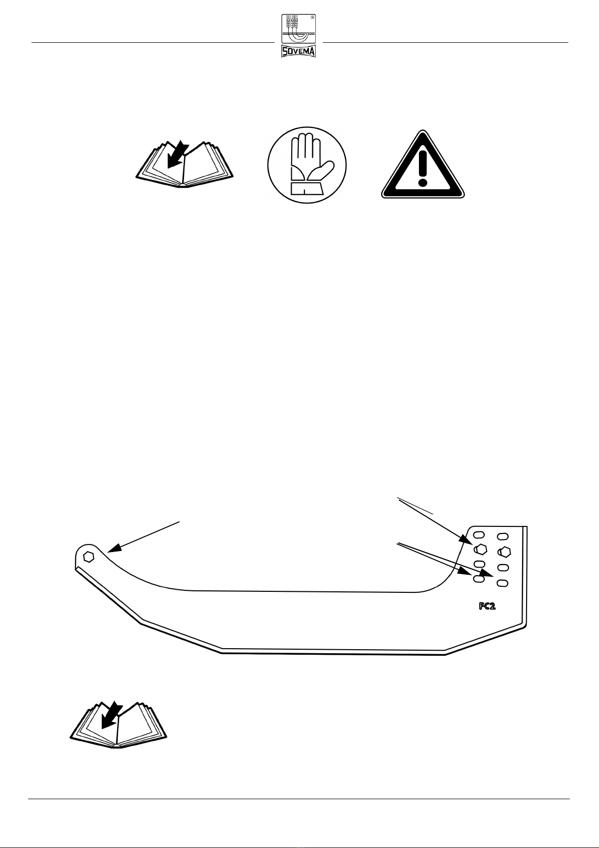
SYMBOLS
These s mbols appear throughout the manual.
Remember their meaning and advice.
CAUTION! YOUR SAFETY IS IN DANGER!
READ CAREFULLY
USE PROTECTIVE GLOVES

IOPERATION & MAINTENANCE MANUAL page 4 Release 2017
GENERAL INFORMATION
All implements with moving parts are potentiall hazardous. The manufacturer has
designed the implement to be used with all the safet equipment properl connected. The
purpose of this manual is to assist ou in safel maintaining and operating the implement.
These instructions have been compiled from our experience.
B following these instructions, ou should be able to develop operating procedures
suitable to our needs.
Illustrations and data used in this manual ma var slightl in some details. Throughout
this manual references are made in left and right directions. These are determined b
standing at the rear of the equipment and facing the direction of advancement.
Even if some illustrations in this manual show the machine
with safet shields removed for a better view, never operate
in these conditions.
BEFORE OPERATING THE IMPLEMENT, ALL SAFETY
SHIELDS OR DEVICES MUST BE MOUNTED!
RIGHT
LEFT
OPERATION & MAINTENANCE MANUAL page 5 Release 2017
SAFETY DECALS
Safet decals on the implement contain important safet warning messages. To prevent
injuries we invite the operator to read them carefull and keep them clean.
Check that all the decals are on the machine. If not, DO NOT USE the machine and
report to the Dealer immediatel to get the decals.
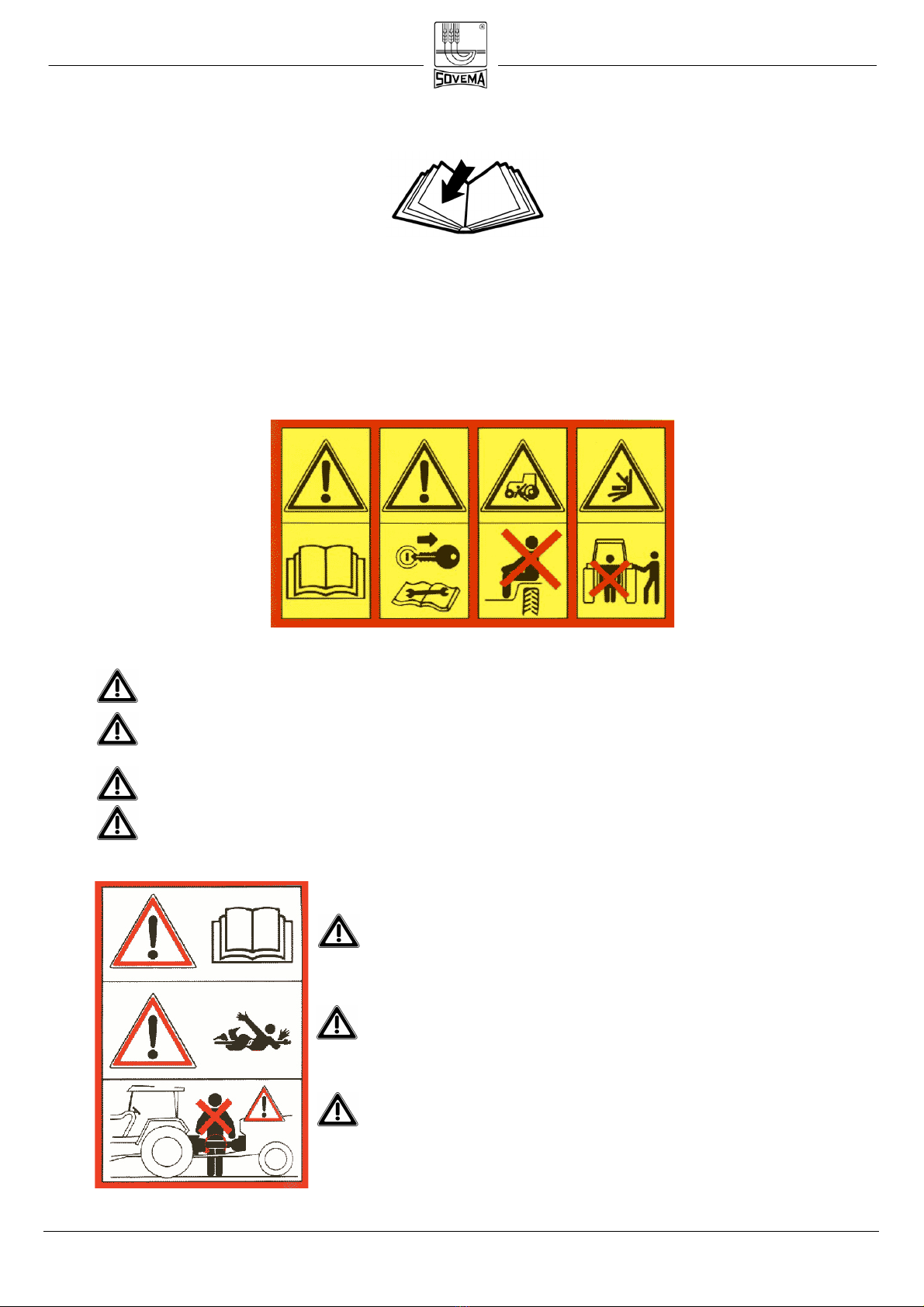
Decals on the machine are as follows:
1 2 3 4
1Before starting operations, read carefull the instruction manual.
2Before maintenance operations, lower the implement to the ground, turn off
the engine, disengage the PTO and read the instruction manual.
3Do not allow riders on the tractor or implement., fatal injuries ma occur.
4Do not stand behind the tractor during operations.
5Before connecting the implement to the PTO, read
the instruction manual carefull .
6Danger of entanglement to the PTO shaft.
7KEEP AWAY from the PTO shaft in operation:
contact can cause death!

OPERATION & MAINTENANCE MANUAL page 6 Release 2017
8 10 11
8Danger. Hands and feet can be injured b moving knives. Keep awa from
the implement.
Danger. Your feet can be injured. Keep awa from the implement.
10 Danger. Your hands can be injured. Do not remove safet shields and keep
awa from moving parts.
11 Danger. Your hands can be injured. Do not remove the cover and keep awa
from moving parts.
12 The machine is designed to be used on
tractors with 540 or 1000 RPM PTO .
13 Caution! During working operations all b -
standers must sta be ond the shown di-
stances from the implement.

OPERATION & MAINTENANCE MANUAL page 7 Release 2017
SAFETY INSTRUCTIONS
Before using the implement ou must be sure to know the main safet precautions; in fact
man accidents are caused b not observing these simple rules.
Sovema S.r.l. declines to the full extent allowed by the applicable laws all liability
and responsibility for any damages of any kind resulting from the breach of the
rules and guidelines expressed in this manual
PRE-OPERATIONAL AND OPERATIONAL RULES.
• Make sure that no one operates the machine unless the have first thoroughl
read and studied this instruction manual and understood all the safet
precautions.
• Keep all guards, shields and safet decals in place and in proper working order
before operating the machine.
• Onl operate with a tractor equipped with an approved Roll Over Protective
S stem (ROPS) and alwa s wear our seat-belt.
• Operate onl in da light or good artificial light.
• Onl trained personnel shall operate the tractor and the implement.
• Personal protection equipment, including safet shoes, safet glasses, hard hat
and gloves are recommended during the different operations. Do not allow long
hair, loose fitting clothing or jeweller to be around moving parts.
• Do not leave the seat until the engine is completely turned off, brakes
locked and ignition key removed.
• Do not allow riders on the machine or tractor at an time.
• Before starting operations, make sure that the tractor's PTO is set to match the
PTO requirements of the implement. The speed is indicated in this manual and
on the implement.
• Alwa s use the PTO shaft supplied b the manufacturer

OPERATION & MAINTENANCE MANUAL page 8 Release 2017
• Make sure the PTO shaft is firml connected to the tractor and the implement and
that the locking pins have snapped shut.
• For connecting and disconnecting the PTO shaft, please refer to the
manufacturer’s instruction manual and to our tractor’s instruction manual.
• Connection and disconnection of the PTO shaft must be performed with the
tractor’s engine turned off.
• Keep hands, feet, hair and clothing awa from moving parts
• To prevent injur b thrown objects DO NOT operate unless all personnel,
livestock and pets are 20 m (65 ft) awa .
• The rotating parts of the machine have been designed and tested for rugged
use. However the can fail upon impact with heav solid objects. Such impact
can cause fragments to be thrown outward at ver high speed. To reduce the
possibilit of serious injur , or even death, never allow the rotating parts to
contact such obstacles.
• Stop the machine and tractor immediatel upon hitting an obstruction. Turn off
the engine, remove the ke , inspect and repair an damage before resuming
operation.
• No repairs or adjustments should be attempted while the machine is connected
to the tractor that is turned on
.
• Disengage tractor PTO and place transmission into neutral before attempting to
start engine.
TRANSPORT SAFETY
• Plan our route to avoid heav traffic.
• For public roads, compl with state and local safet and movement rules.
• Be sure that the implement is in the raised position for transport.
• When ou must drive, do not drink.
• Pa attention to traffic when operating near or crossing roadwa s.
• Reduce speed when transporting mounted implement to avoid bouncing and
loss of steering control.
MAINTENANCE SAFETY
• Good maintenance is our responsibilit . Poor maintenance is an invitation to
trouble.
•Please follow these common practices:
- keep service area clean;
- make sure the area is well lit;
- make sure the tools and the electric appliances are properl grounded;
- make sure the service area is properl ventilated.

OPERATION & MAINTENANCE MANUAL page 9 Release 2017
• Before performing maintenance on this machine, drive to a level area, turn off
the engine, disengage the PTO, lower the machine, set the brakes and remove
the ignition ke
.
• Keep all persons awa from the service area while performing maintenance.
•Always use personal protective equipment.
• Periodicall tighten all bolts, nuts and screws.
• When replacing a mechanical part, alwa s use original spare parts in order not
to compromise the machine and our own safet . The implement manufacturers
assumes no liabilit if replacement parts other than originals are used.
• After servicing, be sure that all safet shields are re-installed properl .
• Make sure that all safet decals are installed, clean and in good condition.
• If the machine is modified from the original design, no responsibilit for the man-
ufacturer can be claimed.

OPERATION & MAINTENANCE MANUAL page 10 Release 2017
MAIN CHECKS LIST
Before connecting the machine to the tractor, read the following instructions:
• Make sure the weight and power of the tractor is suitable to the machine ou want to
connect. If ou have an doubt, please refer to the technical specifications.
• Ensure that all safet decals are properl installed and clean.
• Check the oil level in the gearbox. An low oil level can damage the gears.
• Be sure that all safet shields are properl installed and in good condition.
OPERATION & MAINTENANCE MANUAL page 11 Release 2017
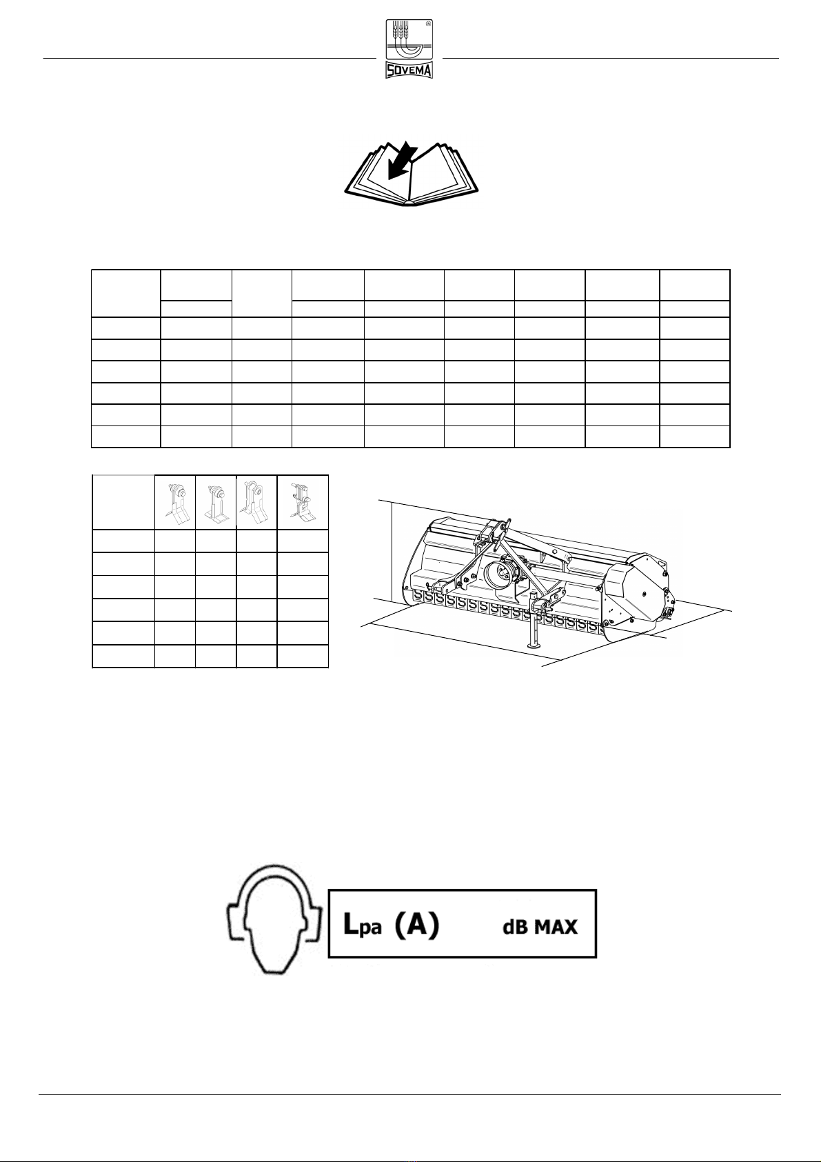
TECHNICAL SPECIFICATIONS
The implement described in this manual is a flail mower from the FC-2 series.
NOISE LEVEL WHEN IDLE
MOD.
FC-2 180 32 32 56
32+16
FC-2 200 40 40 80
40+20
FC-2 230 48 48 96
48+24
FC-2 250 48 48 104
48+24
FC-2 2 0 56 56 120
56+28
FC-2 320 64 64 120
64+32
80
Working
Width PTO Rotor Weight Width -A- Depth -B- Height -C-
cm/inches ( rpm ) ( rpm ) Kg./Lbs. cm/inches cm/inches cm/inches
FC-2 180 185 / 73" 50 - 80 540 1959 600 / 1324 134 / 53" 208 / 82" 107 / 42"
FC-2 200 203 / 80" 55 - 80 540 1959 670 / 1479 134 / 53" 226 / 89" 107 / 42"
FC-2 230 238 / 94" 60 - 80 540 1959 740 / 1633 134 / 53" 261 / 103 " 107 / 42"
FC-2 250 258 / 102" 70 - 100 540 / 1000 1845 / 1950 810 / 1788 137 / 54" 282 / 111" 109 / 43"
FC-2 2 0 290 / 118" 80 - 100 540 / 1000 1845 / 1950 880 / 1942 137 / 54" 323 / 127" 109 / 43"
FC-2 320 320 / 126" 90 - 100 540 / 1000 1845 / 1950 950 / 2097 137 / 54" 343 / 135" 109 / 43"
MOD. HP
A
C
B

OPERATION & MAINTENANCE MANUAL page 12 Release 2017
CONNECTING THE MACHINE
The machines described in this manual do appl to an kind of tractor provided of
universal three-point hitch.
The characteristics (length, diameter of the holes for the lifting pins) of the tractor's lifting
arms depend on the t pe of tractor, therefore it is necessar to prepare the machine in
order to properl hitch the implement.
Before connecting the machine to the tractor ou must make sure that the engine is
turned off, brakes are locked and the ignition ke is removed.
This operation must be performed on a flat area as it is ver dangerous.
Do not allow an one between tractor and implement
while the engine is running.
Follow these instructions:
• Connect the two drawbar of the tractor to the lower plates of the mower b using
two pins and two cotter ke s to lock the pins in place (fig. 1).
PLATES
LOWER
PLATES
Fig.1
UPPER
OPERATION & MAINTENANCE MANUAL page 13 Release 2017
• Connect the 3rd point of the tractor to the high plates of the implement b using a
pin and a cotter ke (fig. 1).
• Lift the implement and fix the stand support high in its socket with the supplied pin.
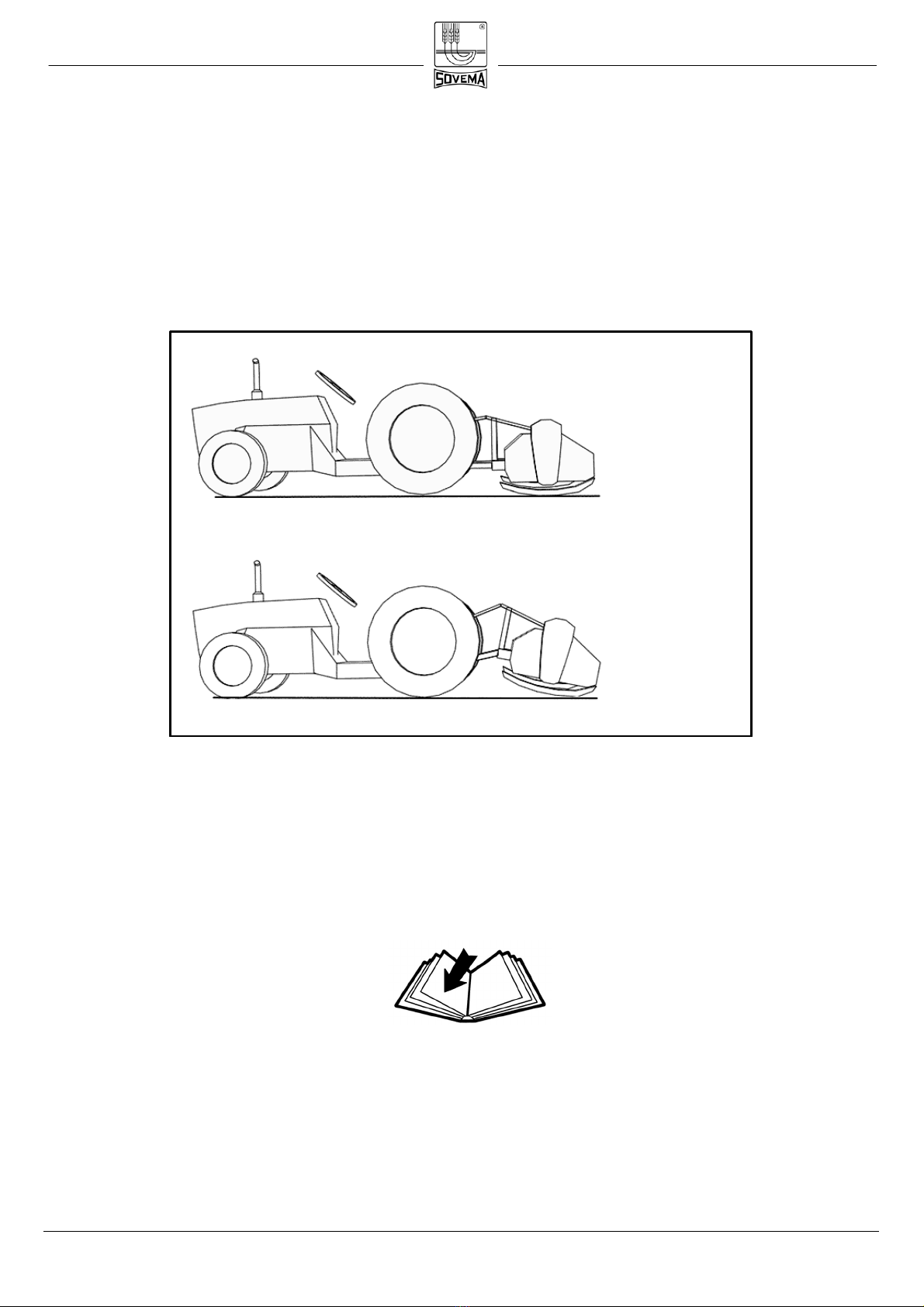
• Lower the implement and adjust it so that it is parallel to the ground. Do this b
adjusting the 3rd point drawbar (fig. 2). This will improve the life-span of the
implement and the PTO.
• Connect the PTO shaft and make sure it is correctl connected to the tractor and to
the implment.
NOTE ON THE PTO SHAFT
Alwa s refer to the manufacturer’s instruction manual. Read it carefull .
Fig.2
NO!
YES!
OPERATION & MAINTENANCE MANUAL page 14 Release 2017
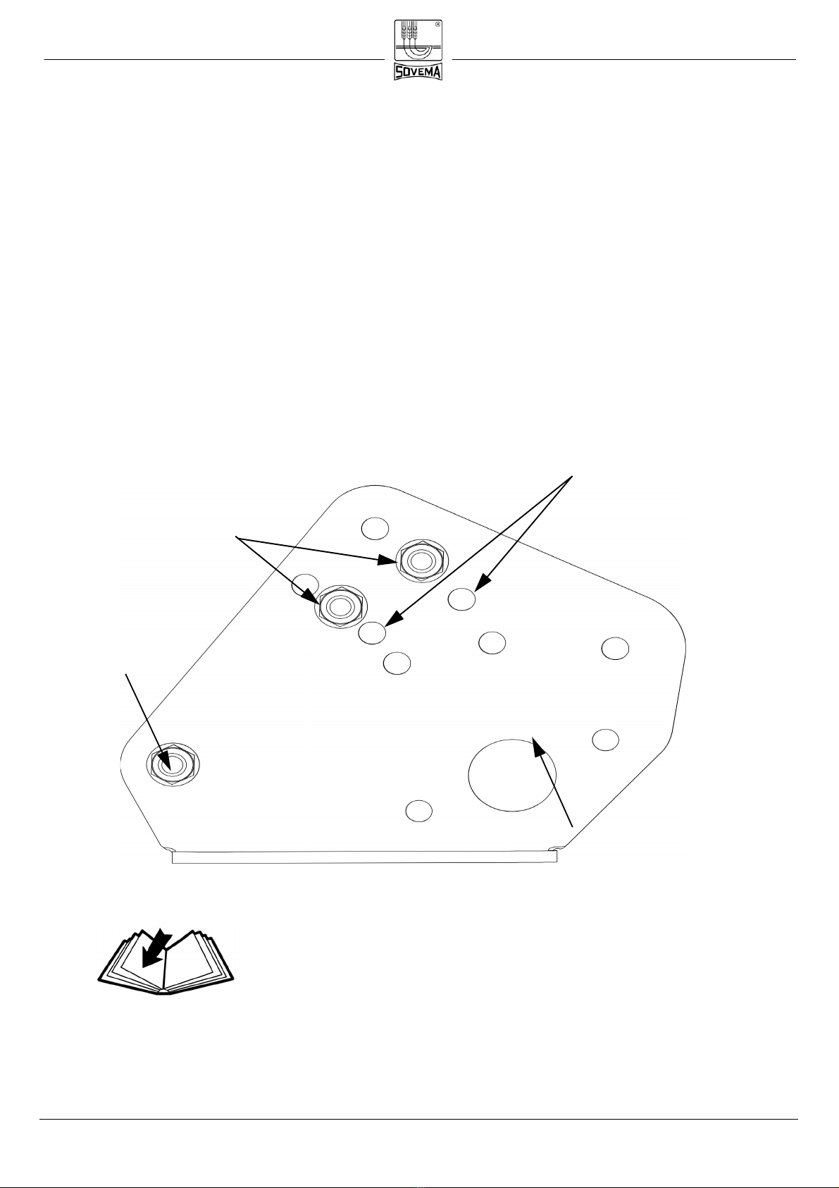
CUTTING HEIGHT REGULATION
Skid-equipped machines
If our implement is equipped with side skids, the height adjustment is made b
regulating the height of the skids as per following instructions: (fig. 1):
• Loosen screw “a”;
• Unscrew screws “b”.;
• Adjust the skid as needed, screwing back screws “b” in one of the pair of holes
located in the skid itself
• Tighten screw “a”.
In order to get an even cut, it is suggested to adjust the
two skids at the same height.
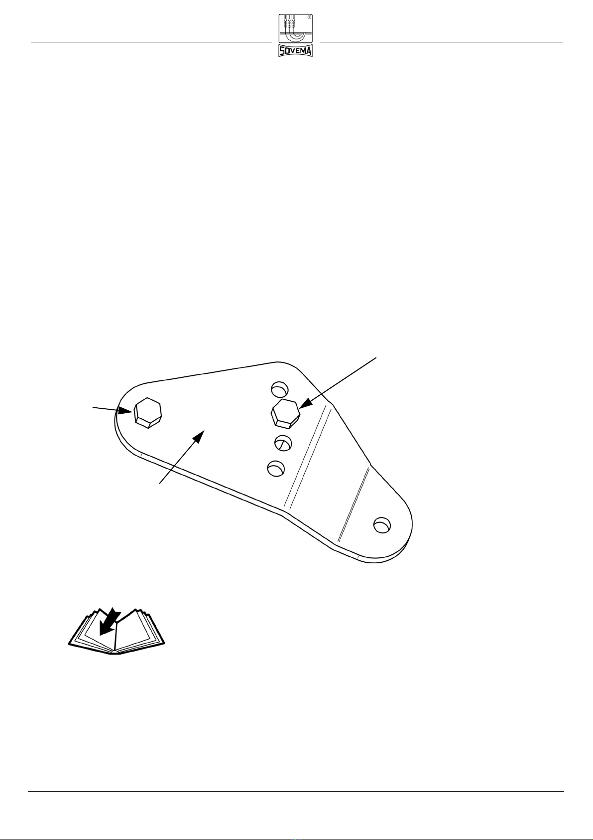
Roller-equipped machines
b
holes
Fig.1
a
OPERATION & MAINTENANCE MANUAL page 15 Release 2017
If our mower is equipped with a rear roller, the adjustment is carried out b regulating
the two roller support plates as follows (fig. 2):
• Loosen screw “c”.
• Unscrew screws “d”.
• Adjust the roller as needed, screwing back screws “d” in one pair of holes located in
the support plate.
• Tighten screw “c”.
In order to get an even cut, it is suggested to adjust the
two plates at the same height.
Holes
c
d
Support plate
Fig.2
OPERATION & MAINTENANCE MANUAL page 16 Release 2017
Wheel-equipped machines
If our mower is equipped with two rear wheels, the cutting height adjustment is carried
out b adjusting the two supports of each wheel. (fig. 3):
• Loosen screw “e”.;
• Unscrew screw “f”;
• Adjust the skid as needed, screwing back screw “f” in one of the holes located in the
support itself;
• Tighten screw “e”.
For each wheel, please adjust the two support at the
same height in order to obtain an even soil.
Support
f
e
OPERATION & MAINTENANCE MANUAL page 17 Release 2017
OPERATING THE IMPLEMENT
After having completed all safet checks and made sure the mower is parallel to the
ground, proceed as follows::
• Raise the machine off the ground in order to let the knives start moving without
touching ground to avoid damages.
• Maintaining the machine raised, engage the tractor PTO at suggested engine RPM.
• Start moving the tractor forward and then graduall lower the machine
CUTTING TIPS
Proper ground speed for cutting will depend upon the
height, t pe and densit of the grass to be cut. However
we suggest not to exceed 7 Kph (4.3 Mph)
.
Lower ground speed allows tall and dense grass cutting. Taking a partial cut and/or
reversing the direction of travel ma also produce a cleaner cut. Remember, sharp knives
produce cleaner cuts and require less power.
Important: Ver low cutting heights should be avoided.
Damaging shock loads occur when the knives strike the
ground repeatedl . This can cause damage to the ma-
chine.
During operation, alwa s raise the machine off the
ground before doing a curve to avoid damage to the roller
supports and to the lateral sides where the skids are po-
sitioned.

OPERATION & MAINTENANCE MANUAL page 18 Release 2017
The machine must be used onl if equipped with all its
components as supplied b the Manufacturer (safet
devices included). The implement must not operate
without the rear shield or modified as to leave the rear
shield open. No other component can be modified.
This manual suits for next models
6
Table of contents
Other Sovema Farm Equipment manuals


Popular Farm Equipment manuals by other brands

LEMKEN
LEMKEN VariTansanit operating instructions

Chore-Time
Chore-Time ATF PLUS Installation and operator's manual

MASCHIO GASPARDO
MASCHIO GASPARDO DINO Use and maintenance / spare parts

LELY
LELY LOTUS 460 Stabilo Operator's manual

agrifac
agrifac CONDOR 2 user manual

sitrex
sitrex Action 120 Use and maintenance manual

horsch
horsch Maestro SW Series owner's manual

LOFTNESS
LOFTNESS Kwik-Pik 480 Operator's manual & parts

Farmet
Farmet KOMPAKTOMAT K500PS operating manual

Alpego
Alpego SKAT K1 Series Use and maintenance manual

Ferrari
Ferrari FPA MULTIPLA Operating and service manual

Wintex Agro
Wintex Agro 1000S instruction manual


