Wintex Agro 1000S User manual

P A G E | 2
Wintex Agro, Vilhelmsborgvej 8C, DK-7700 Thisted
+45 97990800, contact@wintexagro.com, www.wintexagro.com
202203
CONTENTS
1. Safety 3
2. Mounting guidelines 5
a. Mounting on a regular frame 5
b. Mounting on a reversed frame 6
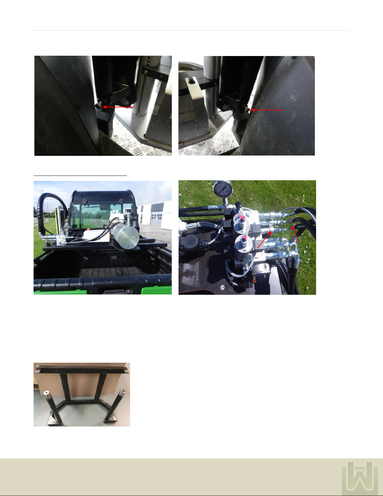
c. Mounting on a pickup frame 7
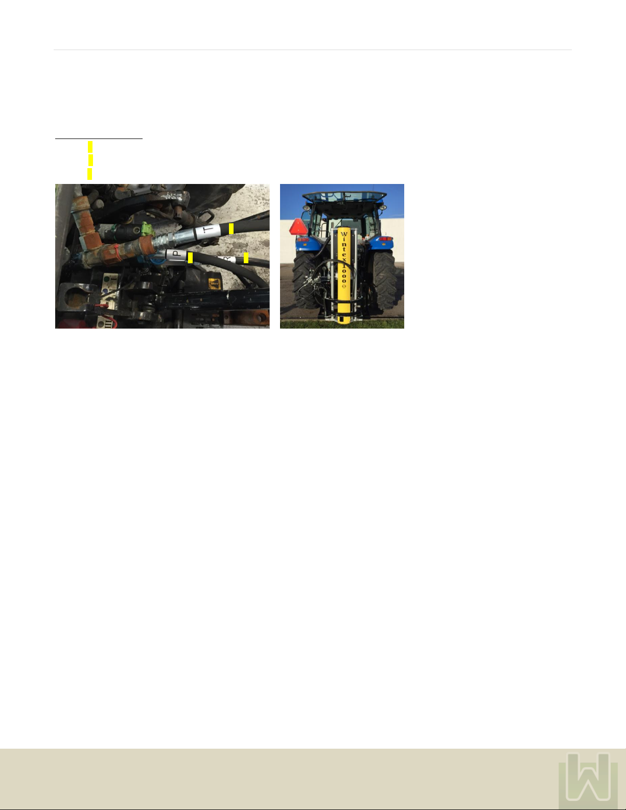
d. Mounting on a tractor 9
3. Using the WINTEX 10
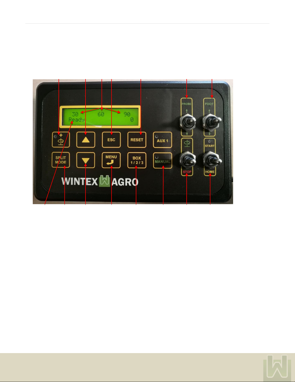
a. Description of the control system 10
b. Connection and start up 10
c. Set up menu 11
d. Settings: depth 11
e. Settings: sticks per sample 12
f. Settings: layers per sample, split mode, soil box 13
g. Soil sampling 13
h. Double rotation 14
i. Foot pressure 14
j. Test menu 15
k. Sensor adjustment 17
4. Maintenance 19
a. Replacement of o-ring, scraper and probe 19
b. Adjustment of chain for rotation 21
c. Adjustment of chain for probe up or down 21
d. Hydraulics 22
e. Manual activation of the hydraulic valves 23
f. Adjustment of the hydraulics 24
g. Dismounting the accumulator 25
h. Control of the accumulator 26
i. Changing oil and oil filter 27
j. Maintenance schedules 29
k. Replacement of sensors 30
5. Problem solving 31
a. Fault location soil sampler 31
b. Fault location hammer 32

P A G E | 3
Wintex Agro, Vilhelmsborgvej 8C, DK-7700 Thisted
+45 97990800, contact@wintexagro.com, www.wintexagro.com
202203
Manufactured by: Wintex Agro
Vilhelmsborgvej 8C
7700 Thisted
Denmark
Type designation: WINTEX 1000s
WINTEX 2000
WINTEX 3000
Voltage: 12 volt DC
Year of production: 2022
1. SAFETY
______________________________________________________________________________________________________________
Please maintain a sufficient distance and stay clear of the working space before starting the soil sampler
When inspecting the soil sampler, you must always activate the emergency stop, and the vehicle must be turned off.
Every time you start the soil sampler you must test the emergency stop. Do not use the soil sampler if the emergency stop does not turn it
off.
The soil sampler has moving, sliding and rotating parts. Keep your limbs away from the soil sampler unless it is turned off and stay away
from the foot / the base of the soil sampler.

P A G E | 4
Wintex Agro, Vilhelmsborgvej 8C, DK-7700 Thisted
+45 97990800, contact@wintexagro.com, www.wintexagro.com
202203
Noise from hammer,
ear protection required
Moving parts,
danger of harming hands
Moving parts,
danger of harming hands
Moving parts,
danger of harming
hands
Entrapment hazard
Danger of cutting,
probe has sharp edges.
Moving parts,
danger of harming
hands
CAUTION required
at the following parts:
IMPORTANT:
Never disconnect the ground
connection to the control system!

P A G E | 5
Wintex Agro, Vilhelmsborgvej 8C, DK-7700 Thisted
+45 97990800, contact@wintexagro.com, www.wintexagro.com
202203
2. MOUNTING GUIDELINES
__________________________________________________________________________________________________________________
2.a. MOUNTING THE WINTEX ON A REGULAR FRAME
Fitting the mounting frame
There are four brackets enclosed in the Wintex package which you need for mounting the soil sampler on the frame.
Please note that it might be necessary to drill new holes for the brackets or weld the brackets to the chassis of the vehicle.
The mounting frame must be located 20 cm above the ground. Optional: The WINTEX can be delivered with 10 cm longer cylinders
which allow the mounting frame to be mounted up to 30 cm above the ground.
The mounting frame under the vehicle The mounting frame on the side of the vehicle
Mounting the stabilizers
Mount the stabilizers at the front and at the back. Then tighten the bolts on the side of the frame.

P A G E | 6
Wintex Agro, Vilhelmsborgvej 8C, DK-7700 Thisted
+45 97990800, contact@wintexagro.com, www.wintexagro.com
202203
The bolts must be tightened to the mounting frame.
Fitting oil pump and Honda GX200 motor
Oil pump and Honda GX 200 motor on a John Deere 855D The numbers on the hoses and the numbers on the hydraulic block
must match and be connected accordingly.
2.b. MOUNTING THE WINTEX ON A REVERSED FRAME
The reversed frame always needs to be customized so that it fits the vehicle in question. Therefore the frame is delivered unpainted

P A G E | 7
Wintex Agro, Vilhelmsborgvej 8C, DK-7700 Thisted
+45 97990800, contact@wintexagro.com, www.wintexagro.com
202203
Here are some examples on how customers have mounted the reversed frame on their vehicles:
2.c. MOUNTING THE WINTEX ON A PICKUP FRAME
The pickup frame includes everything you need to mount the soil sampler in the bed of a pickup truck, but not for mounting the hydraulic
unit. Some vehicles have a bed which is big enough to place the hydraulic unit beside the soil sampler. Other vehicles are narrower or
shorter. Therefore it might be necessary to make a bracket to mount the hydraulic unit on top of the wheel tub or even on the side of the
cargo bed.
Make sure that there is enough space in the bed of the pickup so that the soil sampler can be carried in transport position. Then make
sure that the soil sampler can be tilted at the rear end of the vehicle, and that it can withstand bumper and tow bar.

P A G E | 8
Wintex Agro, Vilhelmsborgvej 8C, DK-7700 Thisted
+45 97990800, contact@wintexagro.com, www.wintexagro.com
202203
The frame needs to be bolted down into these six mounting points. It might be necessary to put big washers underneath the frame to
reinforce the bed.
When the soil sampler is mounted, you need to loosen the position lock bolts on the frame and pull the inner frame backwards. When you
reach the stop, make sure that the position lock bolts engage in the holes to secure the soil sampler. Then release the position lock bolts
of the tilting frame and raise the soil sampler by hand into the working position. Make sure that the lock bolts engage.
The tilting part of the frame is locked with position lock bolts. You can adjust the angle so that you can tilt the soil sampler in a 90-degree
angle to the ground.
Depending on the size of the pickup you need to find a suitable mounting
position for the hydraulic unit. There is no harm in offsetting the soil
sampler to one side of the bed to make space for the hydraulic unit.

P A G E | 9
Wintex Agro, Vilhelmsborgvej 8C, DK-7700 Thisted
+45 97990800, contact@wintexagro.com, www.wintexagro.com
202203
2.d. MOUNTING THE WINTEX ON A TRACTOR
The Wintex is delivered with a 12 V socket which must be connected to the 12 V plug of the tractor.
Connecting the hoses:c
Hose P (1) must be connected to the hydraulic pressure port of the tractor.
Hose R (2) must be connected to the hydraulic return port of the tractor.
Hose T (3) must be connected directly to the pressure less return part of the tractor.
3
2
1

P A G E | 10
Wintex Agro, Vilhelmsborgvej 8C, DK-7700 Thisted
+45 97990800, contact@wintexagro.com, www.wintexagro.com
202203
3. USING THE SOIL SAMPLER
__________________________________________________________________________________
3.a. DESCRIPTION OF THE CONTROL SYSTEM
1 2 3 4 5 6 7
8 9 10 11 12 13 14 15
1: Extra rotation 8: Programme process
2: Up / plus 9: Split mode
3: Preset depth 10: Down / minus
4: Escape 11: Menu / ENTER
5: Reset 12: Sample mode
6: Probe up / down + STOP 13: Manual override
7: Foot up / down + STOP 14: Rotation + STOP
15: START + HOME
Any activation of part no. 6, 7 and 14 will stop the soil sampler.
3.b. CONNECTION AND START UP
Connect the control system to 12 V DC as indicated on the cables. The system needs a 10-amp fuse which must be connected to the
battery as close as possible.
At the start-up, the display shortly shows the version of the software, and then automatically moves on to the start display.
The first row of the display shows the depths which are preset from the factory:

P A G E | 11
Wintex Agro, Vilhelmsborgvej 8C, DK-7700 Thisted
+45 97990800, contact@wintexagro.com, www.wintexagro.com
202203
-WINTEX 1000s: at 30 cm
-WINTEX 2000: at 30 and 60 cm
-WINTEX 3000: at 30, 60 and 90 cm
The second row of the display shows the activated mode of operation. If the soil sampler is resting in “HOME” position, the display will
show the mode “Ready”.
3.c. SETUP MENU
In the “Setup Menu” you can pre-set and adjust several settings.
Press “MENU”. The display will now show “Setup Menu”.
You can shift between settings by using the arrow up and arrow down keys.
The settings can be adjusted by holding the “MENU” key down until the number of the display flashes. Then adjust the figure by using the
arrow up or the arrow down keys. When you have entered the preferred number, press “MENU” (enter) again, and the setting is saved.
3.d. SETTINGS: DEPTH
You can adjust the depth in which the soil samples are taken.
Depending on the type of soil sampler, you can adjust the following depths:
-WINTX1000s: depth 1
-WINTEX 2000: depth 1 and dept 2
-WINTEX 3000: depth 1, depth 2 and depth 3.

P A G E | 12
Wintex Agro, Vilhelmsborgvej 8C, DK-7700 Thisted
+45 97990800, contact@wintexagro.com, www.wintexagro.com
202203
Adjust the depth by using the “MENU”and arrow keys as mentioned previously. Shift or scroll down to the next depth by using the arrow
down key.
3.e. SETTINGS: STICKS PER SAMPLE
You can preset the number of sticks (arrow up for rising the numbers, arrow down for lowering the numbers) for each sample. When
the soil sampler has taken the entered number of sticks, it will not take another sample before you press “RESET”. By entering the
number 99, you can disable this function, and the soil sampler will sample indefinitely.
There is a counter at the bottom on the right which counts the number of sticks in each sample. The counter can be reset to 0 by
pressing “RESET”. You can get access to this function from the start screen, and then press the arrow down key.
You can also see the total amount of sticks taken. This value cannot be reset.

P A G E | 13
Wintex Agro, Vilhelmsborgvej 8C, DK-7700 Thisted
+45 97990800, contact@wintexagro.com, www.wintexagro.com
202203
3.f. SETTINGS: LAYERS PER SAMPLE, SPLIT MODE, SOIL BOX
Determine number of layers
Press the “SPLIT MODE” key to determine the number of the layers.
Depending on the type of soil sampler, it is possible to take samples from one, two or three layers at the same time.
WINTEX 1000s: One number will appear at the top of the display as it only is possible to take a sample from one layer.
WINTEX 2000: Two numbers will appear on the display which means that you will take a sample from two layers. You can also use the
WINTEX 2000 to take a sample from just one layer. In this case press “SPLIT MODE” until just one number appears
on the screen. Use the “SPLIT MODE” key to shift between these options.
WINTEX 3000: Three numbers will be shown on the screen meaning that you are about to take a sample from three layers at the
same time. With the WINTEX 3000 you do also have the option to take a sample from one or two layers. As mentioned
above, use the “SPLIT MODE” key to shift between these possibilities (one number on the screen = sampling will
happen in one layer, two numbers on the screen = sampling from two layers).
Choose soil box
Choosing to deliver the soil into a specific soil box is an option which you have with the WINTEX 2000 and the WINTEX 3000. Shift
between the soil boxes by using the “BOX 1/2/3” key.
Soil box right (WINTEX 2000 and 3000) Soil box left (WINTEX 2000) Soil box left (WINTEX 3000)
Soil box middle (WINTEX 3000)
3.g. SOIL SAMPLING
When everything is set, stay clear of the soil sampler and flip the “START / HOME” switch towards “START”. The soil sampler will now
take a complete soil sample

P A G E | 14
Wintex Agro, Vilhelmsborgvej 8C, DK-7700 Thisted
+45 97990800, contact@wintexagro.com, www.wintexagro.com
202203
Stop the soil sampler
Should you encounter a problem during sampling, you can either activate the emergency stop, or you can flip any of the switches on the
control unit to stop the soil sampler. When flipping the “START / HOME” switch to “HOME”, the soil sampler will return into the start
position.
3.h. DOUBLE ROTATION
Press the key with the rotation symbol to perform an extra rotation which can be advantageous in some kinds of soil.
3.i.
3.i. FOOT PRESSURE
If the soil sampler is not pressed firmly against the ground, you need to adjust the foot pressure by using MENU and arrow keys as
mentioned above.
The pressure should be set at a value that makes the foot of the sampler lift the suspension of the vehicle just a little. If the sampler is
lifted of the ground during sampling, you need to adjust the pressure of the probe.

P A G E | 15
Wintex Agro, Vilhelmsborgvej 8C, DK-7700 Thisted
+45 97990800, contact@wintexagro.com, www.wintexagro.com
202203
3.j. TEST MENU
By entering the test menu you can see the current
-power supply
-pressure
-depth
You can also monitor and see the control system’s
-keys
-switches
-LEDs
-digital inputs
-analog / current inputs
-outputs
-current outputs
-current software version
Enter the test menu by pressing the “MENU” key. The screen will now show “Set up Menu”. Press the arrow down key, and the “Test Menu”
will appear.
Press ”MENU” again, and you will now have access to the above-mentioned content.
You can shift between the content by using the arrow up and arrow down keys.
In some cases it seems like you only can see for example one of four (1/4) “pages” on the screen. To view the other “pages”, press the
“MENU / ENTER” key.

P A G E | 17
Wintex Agro, Vilhelmsborgvej 8C, DK-7700 Thisted
+45 97990800, contact@wintexagro.com, www.wintexagro.com
202203
Diagnostic sheet
3.k. SENSOR ADJUSTMENT
Make sure that the gap between each sensor and the sensor rail is 2-3 mm.
The gap between the sensors for rotation and the rotary sensor plate as well as the gap between the foot sensor and the bolt with the
detector must be 1 mm.
Plug
Type of
signal
Function
Out / in
Trouble shooting
A
12 V
Power supply
12 V
B
-
-
-
C
Can
Terminal
-
D
-
-
-
E2
Out
Foot up valve
12 V; 1,7 A
E3
Out
Foot down valve
12 V; 1,7 A
F2
Out
Probe up valve
12 V; 1,7 A
F3
Out
Probe down valve
12 V; 1,7 A
G2
Out
Rotation valve
12 V; 1,7 A
G3
Out
Main valve
12 V; 1,4 A
H2
Impulse
GPS
12 V; 0,1 A
H3
Power
Transducer power
12 V; 0,01 A
I2
In
Probe up sensor
2,7 V / 10 V
2,7 V indicates that
the sensor is active.
10 V indicates that the
sensor is not active.
12 V indicates that the power
supply for the sensor/cable is
broken.
0 V indicates that the
sensor/cable is shortened.
I3
In
Foot up sensor
2,7 V / 10 V
J2
In
Upper rotation sensor
2,7 V / 10 V
J3
In
Lower rotation sensor
2,7 V / 10 V
K2
In
Height sensor 1 (lower sensor))
2,7 V / 10 V
K3
In
Height sensor 2 (upper sensor)
2,7 V / 10 V
L2
Analog
Oil pressure (foot)
0 –10 V
L3
Analog
Oil temperature
0 –10 V

P A G E | 18
Wintex Agro, Vilhelmsborgvej 8C, DK-7700 Thisted
+45 97990800, contact@wintexagro.com, www.wintexagro.com
202203
If a sensor is adjusted correctly and is in front of the sensor rail, the sensor will light up green. This means that the sensor works.
If the sensor light is orange, the sensor is still working, but either the gap is incorrect, or the sensor is on the edge of one of the sensor rail
holes. If the sensor is adjusted to far away from the rail, the light will also turn orange. The sensor will still give the correct signal, but there
is a risk of wrong readings, thereby giving an incorrect height.
When the soil sampler is moving downwards, the sensors will flash orange and green. This is perfectly normal, as the sensors pass the
holes in the rail. If the sensor stays orange over a longer distance, (10-15 cm) they need to be adjusted, or the rail might be bend.

P A G E | 19
Wintex Agro, Vilhelmsborgvej 8C, DK-7700 Thisted
+45 97990800, contact@wintexagro.com, www.wintexagro.com
202203
4.. MAINTENANCE
______________________________________________________________________________________________________________
4.a. REPLACEMENT OF O-RING, SCRAPER AND PROBE
Revolving platform
Sraper
Probe
O-ring
Replacement of probe
Remove the soil box and unscrew the six bolts with a 5 mm hex key. Both halves of the retainer can now be removed.
Unscrew the three bolts. The revolving platform can now be pulled down along the probe.
Caution: The probe has sharp edges!
Remove the retainer with the special key which is delivered together with the WINTEX. It is now possible to remove the probe
Retainer
Special key

P A G E | 20
Wintex Agro, Vilhelmsborgvej 8C, DK-7700 Thisted
+45 97990800, contact@wintexagro.com, www.wintexagro.com
202203
Replacement of o-ring
When the probe is removed, it is possible to replace the O-ring.
Replacement of scraper
At first force the spring roll pin out. Then replace the scraper and replace the old spring roll pin with a new one.
Other manuals for 1000S
1
This manual suits for next models
2
Table of contents
Other Wintex Agro Farm Equipment manuals
Popular Farm Equipment manuals by other brands

Sulky
Sulky TRAMLINE SE Original instructions

Smithco
Smithco Spray Star 1000 Parts & Service

Poettinger
Poettinger TOP 692 A Operator's manual

Bridgeview
Bridgeview BALE KING 7400 Operator's manual

Amazone
Amazone Precea 9000-TCC Original operating manual

AGRIMASTER
AGRIMASTER GL 60 Use and maintenance manual