Alpego SKAT K1 Series User manual

HYDROPNEUMATIC SUBSOILERS
Codice D08974/9
GB
USE AND MAINTENANCE MANUAL
Da matr:
33930
A matr:
INSTRUCTIONS TRANSLATED FROM THE ORIGINAL
K1
SKAT
K2

MANUALE SKAT K1
-
K2
Old Cod.D08974
New Cod. MANT2010/00722 R.9
2
Copyright ©2009 della Alpego spa® - All rights are reserved. Reprinting or unauthorized use of this manual is strictly forbidden without written permission by Alpego spa
ALPEGO S.p.a.
Sede Amministrativa: Via torri di Confine, 6
36053 GAMBELLARA (VICENZA) - ITALY
Sede legale:
Via Giovanni e Giuseppe Cenzato,9
36045 LONIGO (VICENZA) - ITALY
Tel +39 0444/64.61.00
Fax +39 0444/64.61.99
web site : www.alpego.com
- MACCHINE PER LA LAVORAZIONE
DEL TERRENO
- ERPICI ROTANTI FISSI E PIEGHEVOLI
- COLTIVATORI A DENTI ED A DISCHI
- SEMINATRICI MECCANICHE,
PNEUMATICHE E COMBINATE
- DISSODATORI E RIPUNTATORI
- FRESATRICI E ZAPPATRICI
- TRINCIASARMENTI
- TRINCIASTOCCHI
I
GB
D
F
E
Dichiarazione CE
di conformità’
ai sensi della direttiva
CE 2006/42
La ditta
sottoscritta
EC Certificate
of conformity
conforming to
EEC Directions
2006/42
We
EG Konformitatserklarung
entsprechend der
EG-Richtlinie
2006/42 EWG
Wir
Déclaration de
conformité pour la
CE
conforme à la directive
de la 2006/42 CE
Nous
Declaraciòn CE
de conformidad.
Conforme a la
directiva CE 2006/42
la empresa / el
productor
ALPEGO s.p.a.
VIA TORRI DI CONFINE N°6
36053 GAMBELLARA -(VI)-ITALIA
dichiara sotto
la propria
responsabilità’
che la macchina
modello :
declare in sole
responsability,
that the
product
model :
erklaren in alleineger
Verantwortung,
da das
Produkt
Typ :
déclarons sous
notre seule
responsabilite’
que le produict
modéle :
declara bajo su
propia
responsabilidad que
la màquina
modelo:
Codice / Code: MODELLO MACCHINA
RIPUNTATORI«SEMIN_AS3__40032_IDRO_PLUS»
N° matricola / serial n°:
È’ Conforme ai
requisiti Essenziali
di Sicurezza e di
Tutela della Salute
di cui alla
Direttiva CE
2006/42
Per l’adeguamento
delle macchine
sono state adottate
le norme:
UNI EN ISO 4254-1
UNI EN 982
ISO 11684
to which this
applies, conforms
to the basic safety
and health
requirements of
EC Directions
2006/42
For the adaptation of
it blots some have
been adopted the
norms:
UNI EN ISO 4254-1
UNI EN 982
ISO 11684
auf das sich diese
Erklarung bezeith,
den einschlagigen
grundlegenden
Sicherheits und
Gesundheitsan-
forderungen
der EG-Richtlinie
2006/42 EWG
Für die Anpassung von ihr
befleckt einiges sind
angenommen worden den
Normen:
UNI EN ISO 4254-1
UNI EN 982
ISO 11684
faisant l’objet de
la déclaration est
conforme aux
prescriptions
fondamentales en
matière de sècuritè et
de santè stipulèes
dans la Directive de la
CE
2006/42
Pour l'adaptation d'elle
en éponge ont été
adoptés les normes :
UNI EN ISO 4254-1
UNI EN 982
ISO 11684
està conforme a los
requisitos esenciales de
seguridad y de defeusa de
la salud de la directiva
CE 2006/42
Para la equparaciòn de
las màquinas nan sido
adoptado las normas
UNI EN ISO 4254-1
UNI EN 982
ISO 11684
Gambellara: La ditta

MANUALE SKAT K1
-
K2
Old Cod.D08974
New Cod. MANT2010/00722 R.9
3
Copyright ©2009 della Alpego spa® - All rights are reserved. Reprinting or unauthorized use of this manual is strictly forbidden without written permission by Alpego spa
Consult this manual carefully before using
the machine. Knowing in detail the machine
is essential for safe usage.
Thank you for choosing Alpego, you have purchased a top quality product that is
guaranteed by a decade of experience.
Before leaving the factory, each machine is accurately inspected to guarantee that it is in
perfect condition.
Should you however, find any faults in the material, please contact your retailer
immediately.
Please do not hesitate to contact us should you need further information or assistance,
our aim is to constantly improve the product, keeping it at top level.
LOOK OUT FOR THE TRIANGLE. IT INDICATES DANGER
THE TERM MACHINE REPLACES THE COMMERCIAL DESCRIPTION OF THE ITEM
DESCRIBED IN THIS MANUAL
ALL DATA AND DESCRIPTIONS REPORTED IN THIS MANUAL ARE TO BE CONSIDERED
INFORMATIVE. THE PRODUCER IS NOT BOUND TO MAINTAIN THESE
CHARACTERISTICS WHICH COULD BE VARIED WITHOUT FOREWARNING.

Sommario
Copyright ©2009 della Alpego spa® - All rights are reserved. Reprinting or unauthorized use of this manual is strictly forbidden without written permission by Alpego spa
1. GENERAL INFORMATION........................................................................................................................................1
1.1. PURPOSE OF THE MANUAL .............................................................................................................................1
1.2. DOCUMENTS THAT COME WITH THE MACHINE............................................................................................1
1.3. GUARANTEE.......................................................................................................................................................1
1.4. MACHINE IDENTIFICATION...............................................................................................................................1
2. TECHNICAL SPECIFICATIONS................................................................................................................................2
2.1. MACHINE DESCRIPTION...................................................................................................................................2
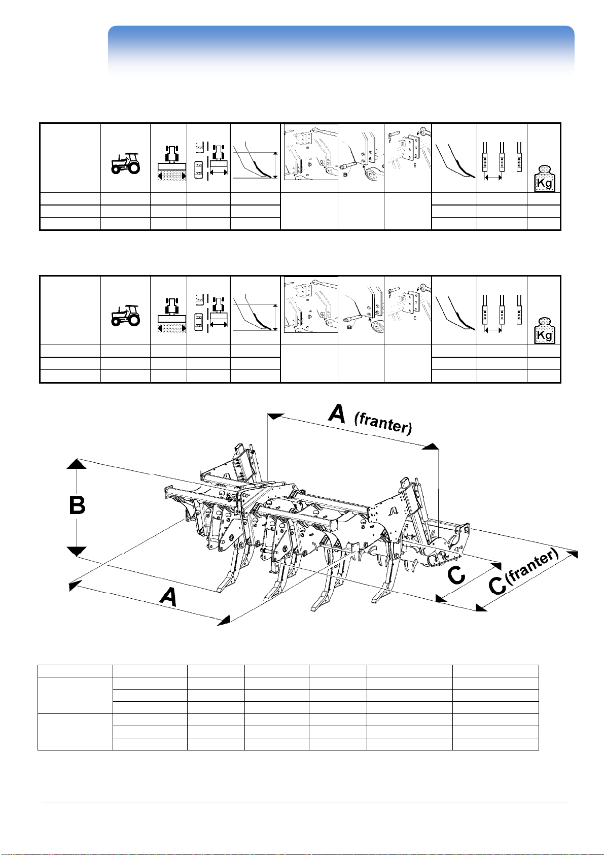
2.2. TECHNICAL INFORMATION CHART K1..........................................................................................................3
2.3. TECHNICAL INFORMATION CHART K2...........................................................................................................3
3. SAFETY REGULATIONS ..........................................................................................................................................4
3.1. USING THE MACHINE SAFELY.........................................................................................................................4
3.2. CARRYING OUT MAINTENANCE SAFELY .......................................................................................................5
3.3. HYDRAULIC CONNECTION...............................................................................................................................5
3.4. ROAD CIRCULATION .........................................................................................................................................5
3.5. CLOTHING...........................................................................................................................................................5
3.6. ECOLOGY............................................................................................................................................................5
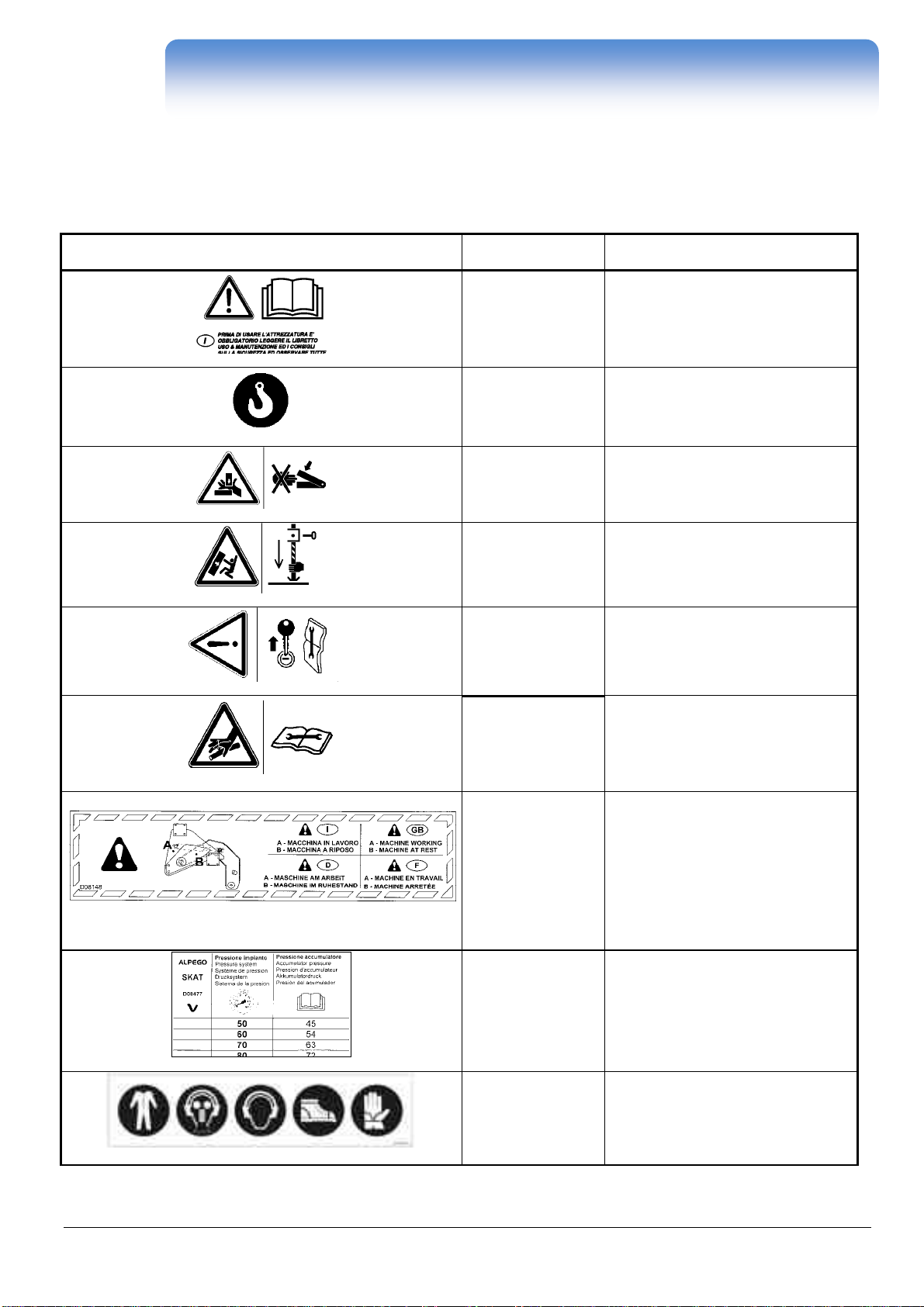
3.7. SAFETY SIGNS...................................................................................................................................................6
4. INSTALLATION .........................................................................................................................................................7
4.1. LIFTING................................................................................................................................................................7
4.2. PREPARATION BEFORE USE...........................................................................................................................7
4.3. CONNECTION TO TRACTOR K1......................................................................................................................9
4.4. CONNECTION TO TRACTOR K2......................................................................................................................9
4.5. CHECKING THE TRACTOR LIFTING FORCE AND STABILITY.....................................................................10
4.6. CONNECTION TO A 3 POINT HITCH K1-K2 ...................................................................................................11
4.7. HYDRAULIC CONNECTIONS TO THE TRACTOR..........................................................................................12
5. USER INSTRUCTIONS............................................................................................................................................13
5.1. USE WITH TRACTORS EQUIPPED WITH CONTROLLED LIFTER STRESS................................................13
5.2. USE WITH TRACTORS WITHOUT CONTROLLED LIFTER STRESS............................................................13
5.3. HYDRRAULIC OPERATION..............................................................................................................................13
5.4. SPECIAL VALVE OPERATION.........................................................................................................................14
5.5. VALVE SETTING – ACCUMULATOR SETTING ..............................................................................................14
5.6. MECHANICAL SAFETY.....................................................................................................................................15
5.7. END OF SEASON OPERATIONS.....................................................................................................................15
6. MAINTENANCE .......................................................................................................................................................16
6.1. CHECKS AND CONTROLS...............................................................................................................................16
6.2. LUBRICATION...................................................................................................................................................16
7. ACCESSORIES........................................................................................................................................................17
7.1. SOD CONTAINING KIT.....................................................................................................................................17
7.2. WINGED SOIL SWEEP....................................................................................................................................17
7.3. REAR WHEEL SET ...........................................................................................................................................17
7.4. FRANTER ROLLER SET K1 – K2.....................................................................................................................18

MANUALE SKAT K1
-
K2
Old Cod.D08974
New Cod. MANT2010/00722 R.9
GENERAL INFORMATION - 1
Copyright ©2009 della Alpego spa® - All rights are reserved. Reprinting or unauthorized use of this manual is strictly forbidden without written permission by Alpego spa
1. GENERAL INFORMATION
1.1. PURPOSE OF THE MANUAL
This manual has been prepared by the machine manufacturer and it is an integral part of the documentation that comes with the
machine.
In this manual you can find detailed and precise explanations regarding the correct use of the machine and it also establishes
correct machine application and its limits.
To guarantee the safety of persons using the machine; working economy and longer duration, you must follow the indications
given in this manual at all times.
This manual has been divided into various sections. Consulting the index makes searching for specific topics easier.
The illustrations in this manual are indicative. Even if you notice a difference with the machine you possess, safety and
information given are still fully guaranteed.
In order to follow a policy of constant development and updating, the manufacturer can make modifications without forewarning.
LOOK OUT FOR THE TRIANGLE. IT INDICATES DANGER
1.2. DOCUMENTS THAT COME WITH THE MACHINE
The following documents must be supplied with the machine:
•User and maintenance manual
•EC declaration of conformity
•Spare parts catalogue
1.3. GUARANTEE
On arrival of the machine, make sure that machine and accessories have not been damaged during transportation.
Any complaints must be made in writing within 6 days from delivery date.
GUARANTEE FORFEITURE
The guarantee is rendered null and void immediately if:
•there is a manoeuvre error
•you use bolts with different dimensions or different material than the one indicated on the cardan shaft limiting device
•the consented power limits are exceeded (see table 2.3)
•the instructions described in this manual are not followed
•original spare parts are not used
•any modification is made to the machine without prior authorisation by the manufacturer.
1.4. MACHINE IDENTIFICATION
At the 3 points of connection to the tractor is placed the identification plate of the machine bearing the following data:
1. Model of the machine
2. Serial number
3. Maximum weight of the machine
4. Costruction year [es: 1305 = 13 (2013) + 05 (may)]
The specified weight refers to the machine provided with the
accessories.

MANUALE SKAT K1
-
K2
Old Cod.D08974
New Cod. MANT2010/00722 R.9
TECHNICAL SPECIFICATIONS - 2
Copyright ©2009 della Alpego spa® - All rights are reserved. Reprinting or unauthorized use of this manual is strictly forbidden without written permission by Alpego spa
2. TECHNICAL SPECIFICATIONS
2.1. MACHINE DESCRIPTION
The machine should be used to work agricultural soil; it breaks the soil deeply without remixing the layers and it is a valid
alternative to ploughing.
The machine can only be used while the soil is flaky enough to obtain sods that pass through the shanks without causing
clogging.
It should be applied to agricultural tractors equipped with a three point hitch which is compatible with the characteristics indicated
in charts 2.2 and 2.3 in the technical information section.
The main parts are:
A) Main frame
B) Shank body
C) Shank support
D) Fast ploughshare
E) Shank protection
F) 3 point hitch
G) Tractor lower hitch
H) Hydropneumatic
accumulator
I) Max. pressure valve
L) Tractor connection
pin
M) Supporting leg

MANUALE SKAT K1
-
K2
Old Cod.D08974
New Cod. MANT2010/00722 R.9
TECHNICAL SPECIFICATIONS - 3
Copyright ©2009 della Alpego spa® - All rights are reserved. Reprinting or unauthorized use of this manual is strictly forbidden without written permission by Alpego spa
2.2. TECHNICAL INFORMATION CHART K1
model
KW mm
mm
mm cat.
ø mm
3° ø mm
n°
mm
K1 5
–
250
67 – 132
2500 2416 500 2° 28 25 5 480 1050
K1 7
-
300
67 – 132
3000 2972 500 7 440 1520
K1 9
-
400
67 - 132
4000 3906 500 9 440 2000
2.3. TECHNICAL INFORMATION CHART K2
model
KW mm
mm
mm cat. ø mm
3° ømm
n°
mm
K2 5
–
250
95 - 191 2500 2416 600 3° 36.5 31.75 5 480 1410
K2 7
-
300
95 - 191 3000 2972 600 7 430 1695
K2 9
-
400
95 - 191 4000 3906 600 9 440 2290
SKAT
Mod.
A (mm)
B (mm)
C (mm)
A (franter) mm
C (franter) mm
K1
K1 5
–
250
2416
1455
1580
2498
2860
K1 7
-
300
2972
1455
1580
3055
2860
K1 9
-
400
3906
1455
1580
3965
2860
K2
K2 5
–
250
2416
1655
1850
2498
3060
K2 7
-
300
2972
1655
1850
3055
3060
K2 9
-
400
3906
1655
1850
3965
3060

MANUALE SKAT K1
-
K2
Old Cod.D08974
New Cod. MANT2010/00722 R.9
SAFETY REGULATIONS - 4
Copyright ©2009 della Alpego spa® - All rights are reserved. Reprinting or unauthorized use of this manual is strictly forbidden without written permission by Alpego spa
3. SAFETY REGULATIONS
3.1. USING THE MACHINE SAFELY
•Read the user and maintenance manual carefully before starting-up, before using the machine and before carrying out
maintenance on the equipment.
•The manufacturer cannot be held responsible for injuries caused to people and animals, or damages caused because
the safety regulations have not been observed by the user.
•The machine cannot be used for different purposes other than those expressly indicated in this manual.
•It is forbidden for people to drive the tractor if they do not have a valid driving licence, if they do not have the necessary
experience, or if they are not in good health.
•Examine carefully the adhesive labels on the machine and make sure you follow their indications.
•Safety stickers should always be legible. They should be kept clean and they must be replaced when they cannot be
read properly (if required, replacements can be requested from your dealer).
•People or animals should never approach the moving area of the machine while it is manoeuvring.
•When you are at work, do not allow people, animals or things to approach the working range of the sods and the stones
that are ejected by the machine.
•It is absolutely forbidden to enter the area between the
tractor and the machine to activate the external commands
of the hydraulic lifter.
•When carrying out any operation on the machine, make
sure nobody gets into the tractor.
•You must always remain seated in the tractor driving seat and you must get off only when the handbrake is pulled up.
•During working stops: switch off the motor, place the machine on the ground and pull the tractor handbrake up.
•Make sure you never work if protections have
been removed.
•Do not use the machine as a means of
transportation for people, animals or things.
•Do not work on ground or in places that could
compromise stability of machine.
•While working do not make any turns while the
machine is planted in the soil, and do not work in
reverse. Always lift machine from soil when
changing direction and reversing
•Do not drop machine violently to the ground. Lower it slowly to have a gradual insertion of the shanks into the ground.
Violent falls would shake all the machine components and you could compromise their integrity.

MANUALE SKAT K1
-
K2
Old Cod.D08974
New Cod. MANT2010/00722 R.9
SAFETY REGULATIONS - 5
Copyright ©2009 della Alpego spa® - All rights are reserved. Reprinting or unauthorized use of this manual is strictly forbidden without written permission by Alpego spa
3.2. CARRYING OUT MAINTENANCE SAFELY
Do not allow unauthorised people to carry out maintenance or any other type of intervention on the machine.
Maintenance and repairs should be carried out in suitably equipped workshops.
When carrying out maintenance on the machine, disconnect the hydraulic pipes from the tractor intake points.
When carrying out any operation on the machine you must always disable the tractor power takeoff, pull the handbrake up,
remove the ignition key and make sure that nobody gets into the tractor.
Use always original accessories and spare parts to respect requirements of the manufacturer. Remember that if you do not follow
these instructions the guarantee will become null and void, and you could cause operational defects that would prejudice machine
safety.
3.3. HYDRAULIC CONNECTION
•When connecting the hydraulic pipes to the tractor, make sure that the machine and tractor hydraulic systems are not under
pressure.
•When connecting the tractor and machine functions (e.g. the hydraulic system), plugs and intakes should be marked by
colours to exclude incorrect connection. You can cause accidents if plugs and intakes are exchanged.
•The hydraulic system is pressurised. To avoid injuries, make use of suitable auxiliary instruments when searching for leaks.
•The pressure indicated for the oleodynamic system should never be exceeded.
3.4. ROAD CIRCULATION
If necessary, the machine can be transported on the roads while hitched to the tractor. The operator must check, compare and
adapt the implement so that it fully complies with the Highway Code in force in the country of use.
Bear in mind the following recommendations:
1) Comply with the instructions in this manual when you hitch the machine to the tractor;
2) The machine must remain blocked and raised from the ground during transport.
3) You must take all possible precautions and comply with the pertinent laws in order to safeguard yourselves and others.
4) Projecting parts and those beyond the width of the tractor must be fitted with the relative protections.
5) The entire implement must be equipped with its own lighting system complete with flashing lights and indicators.
6) Warning boards to indicate the projecting parts of the implement must be affixed where necessary.
7) The braking distance and steering capacity of the tractor are influenced by the weight of the machine hitched to its power lift.
When driving round bends, take great care and allow for the action of the centrifugal force that shifts the machine’s center of
gravity.
8) Comply with the load limits on the axles.
9) Bear in mind the limits imposed by the overhang and projection from the sides of the tractor.
3.5. CLOTHING
Always wear safety gear and clothes. Make sure no dangling parts are present as they may get caught in moving parts.
For the same reasons please always remove watches, rings, necklaces, wristbands etc. Long hair may be a danger as well,
please keep them tied.
If it is Always wear safety gear as required by your local authorities
(safety shoes, gloves, earplugs, masks, etc.)
3.6. ECOLOGY
Regulations in your country regarding the use and disposal of lubricating products; maintenance operations and cleaning of
machine must be respected. Observe carefully the indications given on the packaging of the products used.
Respect current norms also for scrapping of machine.

MANUALE SKAT K1
-
K2
Old Cod.D08974
New Cod. MANT2010/00722 R.9
SAFETY REGULATIONS - 6
Copyright ©2009 della Alpego spa® - All rights are reserved. Reprinting or unauthorized use of this manual is strictly forbidden without written permission by Alpego spa
3.7. SAFETY SIGNS
A good number of labels on the machine point out the sources of danger. Observe them carefully and follow the indications for a
safe use of the machine. These stickers should be kept clean and legible; if damaged they should be replaced.
LABEL
code
INDICATION
D02612
It is a MUST to read the user and
maintenance manual and safety
instructions before using the
equipment. These must be followed
during use.
D02627 Indicates hooking point for machine
transportation
D02613 Indicates the danger of shearing while
machine is working
D02617 Indicates where the supporting leg
should be positioned when the
machine is not being used. This
guarantees stability.
D02615 Indicates the need to switch off the
tractor and remove the ignition key
during maintenance operations
D02624
Indicates danger caused by
pressurised oil should the hydraulic
pipes break. Consult the instruction
manual before repairing hydraulic
systems.
D08148
Indicates the position of the safety pin
onto shank supports. The pin should
be placed in position Awhen the
hydraulic system is pressurised and
the machine is working. The pin
should be placed in position Bwhen
the hydraulic system is no longer
pressurised and the machine is not
working.
D08477
Indicates the pressure setting of
the hydraulic system and the
corresponding accumulator
pressure. The hydraulic system is
standard set at 80 bar, the
accumulator at 60 bar
Q15A00531 The sticker depicts the compulsory
PPE (Personal Protective
Equipment): coverall, mask,
earplugs, safety shoes, gloves

MANUALE SKAT K1
-
K2
Old Cod.D08974
New Cod. MANT2010/00722 R.9
INSTALLATION - 7
Copyright ©2009 della Alpego spa® - All rights are reserved. Reprinting or unauthorized use of this manual is strictly forbidden without written permission by Alpego spa
4. INSTALLATION
4.1. LIFTING
The machine should be lifted and transported with the right means, suitable for its weight, and by personnel trained in this kind of
work.
Hook the machine in the two points indicated in the figure below and go ahead. The loads should not be raised by
more than 200 mm from the ground while carrying out these operations.
Machine ready for shipment
4.2. PREPARATION BEFORE USE
Should the machine be delivered in a “ready for shipment” position (see section 4.1), please proceed as follows:
1) Remove the shanks from the group support assembled on the frame and place them in the correct position on the shank
support.
Shanks on the group support

MANUALE SKAT K1
-
K2
Old Cod.D08974
New Cod. MANT2010/00722 R.9
INSTALLATION - 8
Copyright ©2009 della Alpego spa® - All rights are reserved. Reprinting or unauthorized use of this manual is strictly forbidden without written permission by Alpego spa
2) Insert shaft Donto support Cthen assemble the articulation bolt Awithout
tightening it; just position the screw head and the bolt against the shank
support sheet. Rotate the shank and assemble safety bolt B, then tighten
all the bolts.
3) Lower the rear supporting leg into its position and lock it using the pins.
Insert safety pins B into the 2 front side shank supports.
When the hydraulic system of the machine has been loaded and/or while working, move pins to position A
CENTRAL HOLE
POS.
K1-K2
4) When the previous phases have been carried out the subsoiler can be positioned on a horizontal surface with the
supporting legs and shanks lowered.
Make sure that the pins are in position A.
When moving the subsoiler use the
hooking points indicated on the sticker
(see section 4.1).
As this operation could be dangerous, maximum
caution is expected. Keep unauthorised people away
from the area and check suitability of the available
means. Do not touch hanging loads and keep safety
distance.

MANUALE SKAT K1
-
K2
Old Cod.D08974
New Cod. MANT2010/00722 R.9
INSTALLATION - 9
Copyright ©2009 della Alpego spa® - All rights are reserved. Reprinting or unauthorized use of this manual is strictly forbidden without written permission by Alpego spa
4.3. CONNECTION TO TRACTOR K1
The machine is set for category 2 hitches. Above all check the weight on the axes and, if necessary, ballast the tractor at the
front.
After checking that the tractor can be connected to the machine, move it closer to couple the three points.
Switch off the motor, pull up the handbrake, then get off the tractor and prepare connection of the three points.
4.4. CONNECTION TO TRACTOR K2
The machine is set for category 3ª / 3ª USA / 4ª hitches.
Above all check the weight on the axes and, if necessary, ballast the tractor at the front.
After having made sure that the tractor can be connected to the machine, move it closer in order to couple the three points.
Switch off the motor, pull up the handbrake, then get off the tractor and prepare for connection of the three points.
*

MANUALE SKAT K1
-
K2
Old Cod.D08974
New Cod. MANT2010/00722 R.9
INSTALLATION - 10
Copyright ©2009 della Alpego spa® - All rights are reserved. Reprinting or unauthorized use of this manual is strictly forbidden without written permission by Alpego spa
4.5. CHECKING THE TRACTOR LIFTING FORCE AND STABILITY
When an extra machine is added to the tractor, becoming a part of the tractor itself, as far as road circulation
is concerned, stability is different and driving and working become more difficult.
Depending on the composition of the machine, it is therefore advisable to add ballast to the front part of the tractor so
as to adequately distribute the weight on the axles.
A
Distance of the f ront axle f rom the f ront ballast (m)
1
1
B
Tractor wheelbase (m)
2
C
Distance of the rear axle f rom the implement’s lower hitch (m)
2
Gv
Ballast weight (kg)
3
Te
Empty weight of the tractor
2
Tv
Load on the tractor’s f ront axle when empty
2
Th
Load on the tractor’s rear axle when empty
2
Lb tot
Distance f rom the lower hitch to the center of grav ity of the complete implement combination (m)
3
Lb1
Distance f rom the lower hitch to the center of grav ity of the f irst combi machine (m)
1
Lb2
Distance f rom the lower hitch to the center of grav ity of the second combi machine (m)
1
Mb1
Ov erall weight of the f irst implement (kg)
4
Mb2
Ov erall weight of the second implement (kg)
4
Mb tot
Ov erall weight of the complete implement combination (kg)
3
1) Must be measured.
2) Consult the tractor’s operation and maintenance manual.
3) Must be calculated.
4) Consult the operation and maintenance manual of the required implement.

MANUALE SKAT K1
-
K2
Old Cod.D08974
New Cod. MANT2010/00722 R.9
INSTALLATION - 11
Copyright ©2009 della Alpego spa® - All rights are reserved. Reprinting or unauthorized use of this manual is strictly forbidden without written permission by Alpego spa
The ballast to add is calculated with the f ormula
Gv min. = (Mb tot x (C + Lb tot)) – (Tv x B) + (0,2 x Te x B)
-----------------------------------------------------------------
A+B
- The distance f rom the center of grav ity of the combi machine to the lower hitch of the tractor is calculated with
the f ormula
Lb tot = (Lb1 x Mb1) + (Lb2 x Mb2) + (Lb….x Mb….)
---------------------------------------------------------------
Mb1+Mb2 +Mb…
- The ov erall weight of the entire combi machine is calculated with the f ormula
Mb tot = Mb1+Mb2+Mb…..
On the front bridge of the tractor it must, in any case,
burden at least 20% of the total mass tractor-tool in march
order. It is how ever to hold present that, beyond to the
appropriated one chosen the connection tractor-tool, the
application of ballasts in front position, the limits and with
the modalities indicated from the constructor of the tractor,
can improve of the stability . Moreover, with firm tractor it
must be made to come down to earth the too lavoiding the
ref ore possible in voluntary reductions, improving at the
same time, the stability .
4.6. CONNECTION TO A 3 POINT HITCH K1-K2
Proceed with connection of the lower arms and the third tractor point as
indicated in the figure:
a) Remove nuts and bolt A
b) Remove pins Band C
c) Insert the detent of the tractor lower arms into the lower sockets D.
If using category 3 hitches, respect the position of distancers Eand F
(with category 2 hitches, the distancers should be inverted)
d) insert pins C, nuts and bolts A.
e) connect the tie rod of the third tractor hitch in the same way, inserting pin B
and nuts and bolts Ainto one of the three holes. Select hole according to
tractor lifting force.
Tractor wheelbase B= m
Distance of the front axle
from the front ballast:A= m
Tractor weight Te= Kg
Ballast weight: Gv= Kg
Load on the tractor’s axle
when empty: Tv= Kg
Implement weight: Mb tot= Kg
Tot center of gravity length: Lb tot= m

MANUALE SKAT K1
-
K2
Old Cod.D08974
New Cod. MANT2010/00722 R.9
INSTALLATION - 12
Copyright ©2009 della Alpego spa® - All rights are reserved. Reprinting or unauthorized use of this manual is strictly forbidden without written permission by Alpego spa
4.7. HYDRAULIC CONNECTIONS TO THE TRACTOR
The good performance of the implement depends largely from its correct use and from a regular maintenance program.
It is therefore advisable to follow carefully what is described in order to prevent any trouble which may impair the
performance of the machine and shorten its lifespan. It is also important to comply with the rules contained in this
manual, since the Manufacturer disclaims all responsibility for damages due to negligence or the non-observance of
said rules.
1. Connect the quick-plug of the hydraulic circuit to a socket of the tractor
( a pressure between 160/190 bar is required);
2. Gradually put the hydraulic system under pressure - shown by the manometer -
until the working pressure necessary for your particular type of soil is reached
Suggested pressure = 80/100 bar (see chart 5.5)
Remove the two pins from the side shaft support B and place
them in their correct place in the tractor connections A

MANUALE SKAT K1
-
K2
Old Cod.D08974
New Cod. MANT2010/00722 R.9
USER INSTRUCTIONS - 13
Copyright ©2009 della Alpego spa® - All rights are reserved. Reprinting or unauthorized use of this manual is strictly forbidden without written permission by Alpego spa
5. USER INSTRUCTIONS
Follow all the safety regulations described in section 3 of this manual and consult the
documentation regarding tractor use carefully.
When the machine is connected to the tractor, activate the lifting
device then raise the support leg as indicated in the diagram
(do not move machine while leg is in resting position).
5.1. USE WITH TRACTORS EQUIPPED WITH CONTROLLED LIFTER STRESS
Start working by moving forward at a slow speed and lowering the shanks slowly until you reach the working depth needed.
Select working speed according to the soil and the power you have, keeping in mind that the faster the speed forward, the better
the soil breaking effect is.
5.2. USE WITH TRACTORS WITHOUT CONTROLLED LIFTER STRESS
If you are working with a tractor that does not have a controlled lifter stress device, the working depth can be regulated with the
right accessories that can be supplied upon request, such as a SET OF FRANTER ROLLERS or a set of rear wheels.
These accessories support the machine and regulate the working depth. It is advisable to start working at minimum depth then to
lower gradually until you reach the required working depth.
5.3. HYDRRAULIC OPERATION
The SKAT K1 – K2 series hydraulic subsoilers come with a cylinder hydraulic system. The single-acting cylinders work on the
shanks, lifting them while working (when there is an excessive force) and immediately repositioning them when the obstacle has
been passed.
Valve connection chart
(letters are highlighted on
the valve).
A) Accumulator entry
P) Tractor oil entry
L) Single-acting cylinder
T) Oil discharge
M) Pressure gauge entry
U) Cylinder connections

MANUALE SKAT K1
-
K2
Old Cod.D08974
New Cod. MANT2010/00722 R.9
USER INSTRUCTIONS - 14
Copyright ©2009 della Alpego spa® - All rights are reserved. Reprinting or unauthorized use of this manual is strictly forbidden without written permission by Alpego spa
5.4. SPECIAL VALVE OPERATION
This hydraulic device (ref. V) makes it possible to send to the accumulator A
the oil of the pistons of the shanks which are working under particularly severe
conditions.
Under extreme conditions, should all the shanks of the implement kick back at
the same time, a pressure of over 180 bar (max. service pressure in the
accumulator) would suddenly build up. In this case the valve will discharge
through the transparent tube T the quantity of oil necessary to keep the pressure under the maximum level allowed.
Above the valve there is a manometer M which shows the actual pressure in the
circuit.
Underneath there is a valve of max. pressure E, already calibrated at 180 bar to
guarantee the safety of the entire circuit.
The working pressure is adjusted directly from the tractor through its hydraulic
distributor.
In order to disconnect the hydraulic hose P for the connection to the tractor
hydraulic system it is necessary to eliminate the pressure from the
quick-coupling plug by shutting off the tap which is mounted at the end.
When storing the implement it is necessary to insert the pins into the
supports of the front shanks when these are in the idle position (see sticker).
While operating with the implement frequently check on the manometer M that the working pressure is of 80 bar.Should a
decrease caused by excessive stress occur, it is mandatory to restore the pressure by supplying more oil from the tractor.
5.5. VALVE SETTING – ACCUMULATOR SETTING
The working pressure of the shanks can be adjusted directly
from the tractor by acting on the distributor.
The recommended pressure is shown on the sticker -
reproduced here at the side - which is applied on the
accumulator .
This pressure is correct for working in medium-hard soils at
medium working depths.
Should the working conditions be different, it is possible to
increase or decrease the working pressure through the tractor
distributor, although remaining within the following range of
values: min. 70 bar, max. 110 bar.
(●) Recommended working pressure

MANUALE SKAT K1
-
K2
Old Cod.D08974
New Cod. MANT2010/00722 R.9
USER INSTRUCTIONS - 15
Copyright ©2009 della Alpego spa® - All rights are reserved. Reprinting or unauthorized use of this manual is strictly forbidden without written permission by Alpego spa
5.6. MECHANICAL SAFETY
As well as being equipped with a
hydraulic safety device, each
machine shank has a bolt that
breaks by traction each time there
is a force above the machine
capacity. This safeguards
machine structure from excessive
forces. In addition, to guarantee
structure resistance, do not make
turns and do not change direction
while shanks are underground
because you would modify the
safety devices effect.
5.7. END OF SEASON OPERATIONS
If the machine is not used for long periods, the following operations should be carried out to maintain integrity
of parts of parts and machine:
•Lower supporting leg and lock it with the pin.
•Insert safety pins in the shank lateral supports as shown in pos. B(see section 4.2).
•Depressurise the hydraulic system (see section 5.4).
•Separate the tractor and the subsoiler.
•Wash machine carefully, then dry it.
•Make sure that the machine is in perfect condition.
•
Protect all unpainted metal parts with lubricants, then cover the machine or place it in a dry area.
The ground should be solid to guarantee machine stability. It is an advantage for you to find machine ready for use.

MANUALE SKAT K1
-
K2
Old Cod.D08974
New Cod. MANT2010/00722 R.9
MAINTENANCE - 16
Copyright ©2009 della Alpego spa® - All rights are reserved. Reprinting or unauthorized use of this manual is strictly forbidden without written permission by Alpego spa
6. MAINTENANCE
6.1. CHECKS AND CONTROLS
During the first 50 working hours it is a good idea to check the tightness of all the bolts, because the power generated while
working creates structure movement. If necessary, tighten as indicated in the chart below.
Repeat this operation on a regular basis, every 200 working hours.
DRIVING TORQUE RECOMMENDATIONS FOR NUTS AND BOLTS
nominal diameter
M8
M10
M12
M14
M16
M20
M22
M24
hexagon wrench mm. 13 17 19 22 24 30 32 36
driving torque Kgm
3
6
10
14
21
40
54
70
driving torque Nm
30
59
98
137
205
390
350
685
6.2. LUBRICATION
The machine should be lubricated through greasing holes A
positioned on the articulation head of the cylinders and on the
shank supports.
Lubricate every 120 working hours.
For machines that come with FRANTER rollers, lubricate also roller supports through position B
Lubricate every 8 / 10 working hours.
This manual suits for next models
7
Table of contents
Other Alpego Farm Equipment manuals
Popular Farm Equipment manuals by other brands

WALTERSCHEID
WALTERSCHEID HOLHS Mounting and operating instructions

Raven
Raven SmarTrax Spra-Coupe 220 installation manual

Kubota
Kubota AP-SRF2772 Operator's manual

MacDon
MacDon M155E4 Operator's manual

Landoll
Landoll Icon 1205 Carry All Service and parts manual

Toro
Toro Groundsmaster 4500-D Operator's manual