Sovema EM-3 User manual


Pag.1
CONGRATULATIONS
Dear Owner,
Thank you for buying a SOVEMA manufactured product.
Your new machine is carefully designed and manufactured to give you
superior performance and dependable service, if properly operated and
maintained.
You will find this machine to be rugged and reliable when matched to
the suggested horsepower operating range.
Much time has been invested in providing safety and protection. Please
carefully read this manual. It tells you how to safely and easily assemble,
operate and maintain your machine.
Be sure that you and any other operator carefully follow the recom-
mended safety practices at all times. Failure to do so could result in per-
sonal injury or property damage.
Of course, if you should ever have any problems or questions, please
contact your local SOVEMA dealer or contact us at the addresses or
numbers indicated in this manual.
SOVEMA manufactures a variety of innovative equipment. If you are
interested in reviewing our full line, please contact us.
Thanks for your choice.
Ginettino Mayer
President

Pag.2
TABLE OF CONTENTS
- SYMBOLS Page 3
- GENERAL INFORMATION Page 4
- SAFETY AND WARNING DECALS Page 5
- SAFETY INSTRUCTIONS Page 7
- MAIN CHECK Page 10
- TECHNICAL SPECIFICATIONS Page 11
- ATTACHING THE MACHINE TO THE TRACTOR Page 12
- CUTTING HEIGHT ADJUSTMENT Page 16
- BEGINNING WORK Page 18
- TROUBLE SHOOTING Page 19
- DISCONNECTING THE MACHINE FROM THE TRACTOR Page 22
- STORING OF THE MACHINE Page 23
- MAINTENANCE Page 24
- TOXICOLOGICAL INFORMATION Page 27
- SPARE PARTS LIST Page 29
- WARRANTY POLICY Page 36
- SOVEMA PRODUCT LINE Page 40

Pag.3
MEANS: CAUTION!
YOUR SAFETY IS INVOLVED
MEANS: USE PROTECTIVE GLOVES
MEANS: READ CAREFULLY
SYMBOLS
These symbols appear throughout the manual.
Remember their meaning and advice.
Pag.4
GENERAL INFORMATION
All implements with moving parts are potentially hazardous. The manufacturer has designed
the implement to be used with all the safety equipment properly attached. The purpose of this
manual is to assist you in safety maintaining and operating the implement.
These instructions have been compiled from our experience.
Through this experience and these instructions, you should be able to develop operating proce-
dures suitable to your particular situation.
Illustrations and data used in this manual may vary slightly in some details. Throughout this
manual references are made in left and right directions. These are determined by standing at the
rear of the equipment and facing the direction of forward travel.
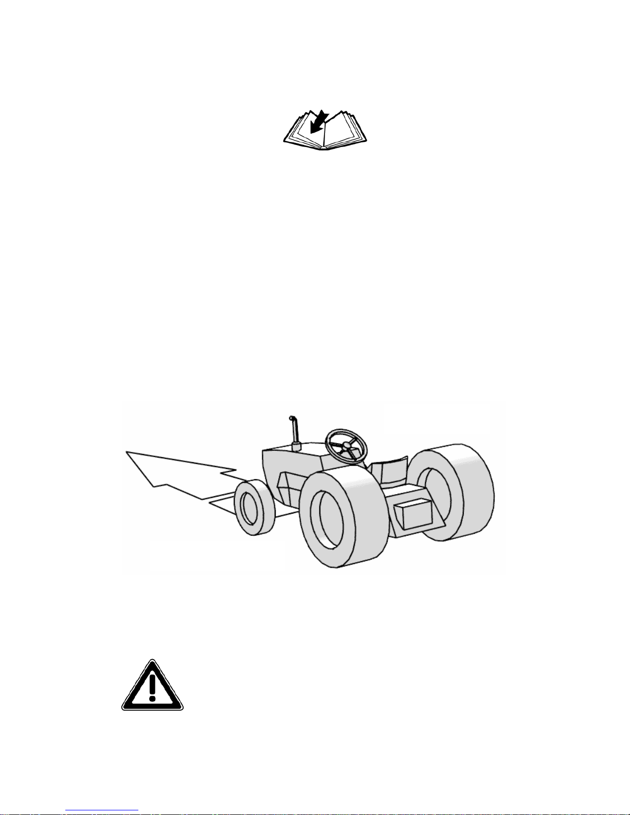
Even if some illustrations in this manual show the machine
with safety shields removed for a better view, never operate in
these conditions.
BEFORE OPERATING THE IMPLEMENT, ALL SAFETY
SHIELDS OR DEVICES MUST BE MOUNTED
RIGHT
LEFT
Pag.5
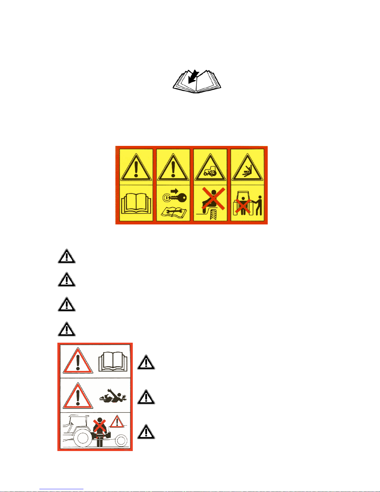
SAFETY AND WARNING DECALS
Safety decals on the implement contain important safety warning messages. To prevent injuries
we invite the operator to read them carefully and keep them clear. Check that all the decals are on
the machine. If not, DO NOT USE the machine and report to the Dealer immediately to get the
decals. Decals on the machine are the following and mean:
1 2 3 4
1. Before operating the equipment, read carefully the operator’s manual.
2. Before maintenance operation, lower the implement, shut off the engine and read the
operator’s manual.
3. Do not allow riders on tractor or implement.
4. Do not stand behind the tractor during the operations.
5. Before operating the equipment, read carefully the opera-
tor's manual.
6. DANGER! Entanglement of driveline..
7. KEEP AWAY from driveline in operation: contact can
cause death!
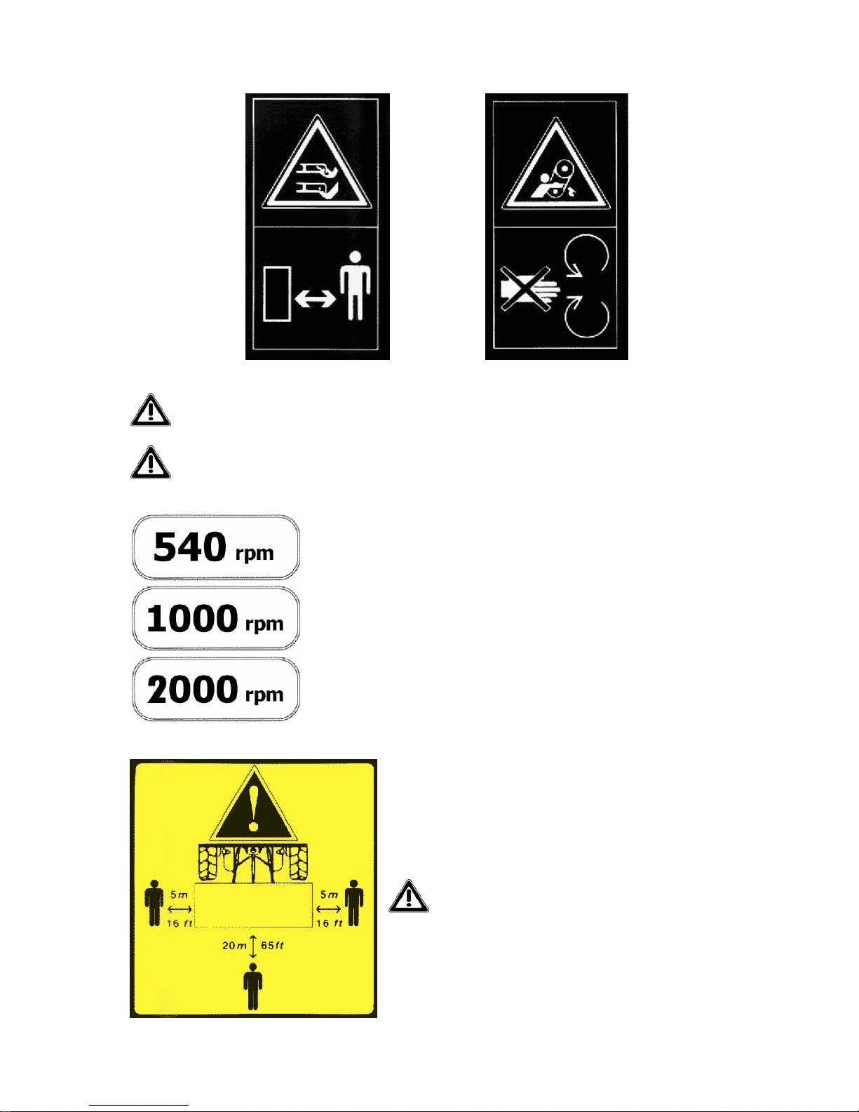
8. Danger. Your hands and feet can be injured by moving parts. Keep away from the im-
plement.
9. Danger. Your hands can be injured. Do not remove the cover and keep away from
moving parts.
10. The machine is designed for use on tractors with 540 RPM PTO
only
11. The machine is designed for use on tractors with 1000 RPM
PTO only
12. The machine is designed for use on tractors with 2000 RPM
PTO only
13. Caution! During working operations all by-
standers must stay beyond the shown distances
from the implement.
Pag.6
8 9

Pag.7
SAFETY INSTRUCTIONS
Before using the implement you must be sure to know the main safety precautions; in fact many
accidents are caused by not observing these rules.
Pre-operational and operational safety rules
Make sure that no person operates this machine unless they first, thoroughly read and
studied the operator instructions for this machine and understood all the safety precau-
tions.
Keep all guards, shields and safety decals in place and proper working order before oper-
ating this machine.
Operate only with a tractor equipped with an approved Roll Over Protective System
(ROPS) and always wear your seat-belt.
Operate only in daylight or good artificial light.
Only trained personnel can operate with the tractor and the implement.
Personal protection equipment, including safety shoes, safety glasses, hard hat and
gloves are recommended during the different operations. Do not allow long hair, loose
fitting clothing or jewellery to be around moving parts.
Do not leave the tractor seat until the engine is completely turned off, brakes locked
and ignition key removed.
Do not allow riders on the machine or tractor at any time. No safe place for any rider.
Before starting to operate, be sure that the tractor's PTO is set to match the PTO require-
ments of the implement. The speed is indicated in this manual and on the implement.
Do not use different driveline . Always use type and size supplied by the manufacturer.
Make sure driveline spring-activated locking pin operate freely and are seated firmly in
tractor PTO stub shaft groove.
Pag.8
For engaging or disengaging the tractor PTO, refer to your tractor manual.
Connect and disconnect PTO shaft only when tractor engine is turned off.
Keep hands, feet, hair and clothing away from moving parts.
To prevent injury by thrown objects DO NOT operate unless all personnel, livestock and
pets are 20 m (65 ft) away.
The rotating parts of the machine have been designed and tested for rugged use. However
they could fail upon impact with heavy solid objects. Such impact could cause the broken
objects to be thrown outward at very high speed. To reduce the possibility of serious in-
jury, or even death, never allow the rotating parts to contact such obstacles.
Stop the machine and tractor immediately upon striking an obstruction. Turn engine off,
remove key, inspect and repair any damage before resuming operation.
No repairs or adjustments should be attempted while the machine is attached to a tractor
that is turned on.
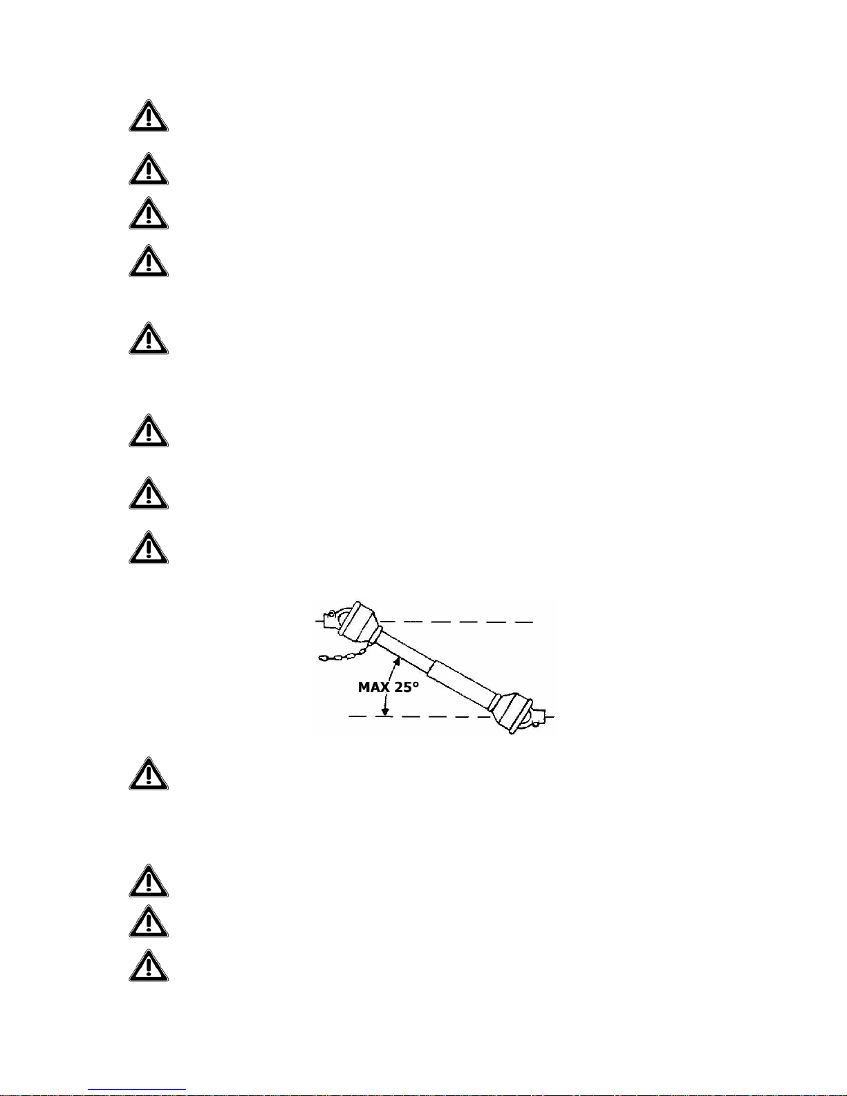
Working inclination of PTO driveline must not exceed 25° (see fig.1). Greater working
angles will damage the PTO and serious personal injury could occur as well.
Disengage tractor PTO and place transmission into neutral before attempting to start en-
gine.
Transport safety
Plan your route to avoid heavy traffic.
For public roads, comply with state and local safety and movement rules.
Be sure that the implement is in the raised position for transport.

Pag.9
When you must drive, do not drink.
Pay attention to traffic when operating near or crossing roadways.
Reduce speed when transporting mounted implement to avoid bouncing and loss of steer-
ing control.
Pay attention when you turn curves or you go up and down on hills with the implement.
Be sure that at least 25% of the tractor’s weight is on the front wheels to maintain safe
steering. Drive at a low speed.
NEVER allow riders on implement or tractor. Falling off can kill.
Be a safe and courteous driver.
Maintenance safety
Good maintenance is your responsibility. Poor maintenance is an invitation to trouble.
For maintenance follow these common practises:
- keep service area clean;
- use adequate illumination for the job;
- be sure tools and electrical outlets are properly grounded;
- make sure there is plenty of ventilation.
Before making maintenance on this machine, drive to a level area, disengage the PTO,
lower the machine, turn off the engine, set the brakes and remove the ignition key.
Keep all persons away from operator control area while performing maintenance.
ALWAYS use personal protection devices.
Periodically tighten all bolts, nuts and screws.
The implement manufacturers assumes no liability if replacement parts other than the
original factory parts are used.
After servicing, be sure that all safety shields are re-installed properly.
Be sure that all safety decals are installed, clean and in good condition.
If the machine is modified from the original design, no responsibility for the manufacturer
can be claimed.

Pag.10
MAIN CHECK LIST
Before connecting the machine to the tractor, read the following instructions:
• Be sure the weight and power of the tractor is correct with the machine you want to con-
nect. If you have any doubt, see the technical specifications.
• Ensure that all safety decals are properly installed and clean.
• Check oil in the gearbox. With low oil, gears get damaged.
• Be sure that all safety shielding is properly installed and in good condition.
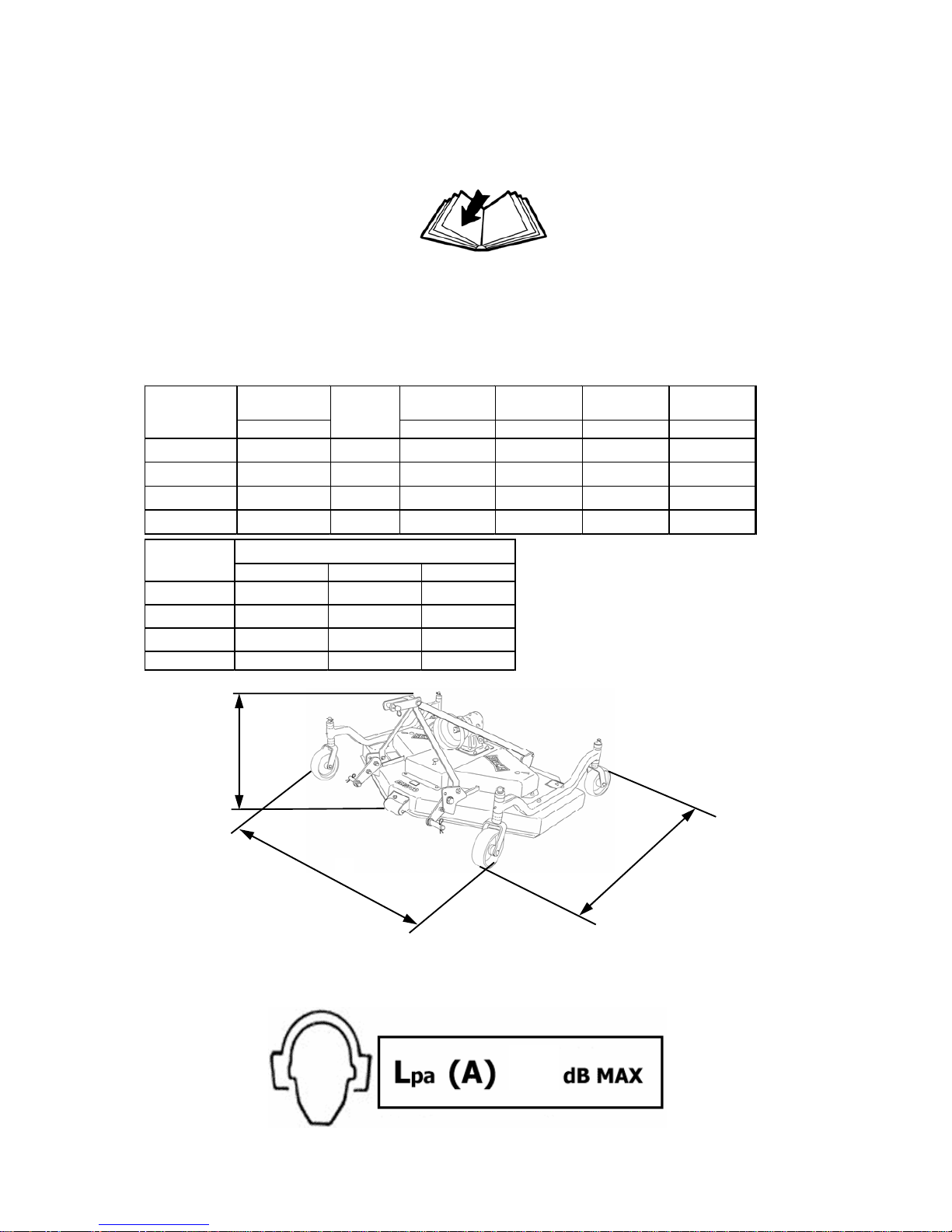
TECHNICAL SPECIFICATIONS
The machine described in this manual is a grass cutter of the EM 3 series.
EM 3 SERIES
LEVEL OF NOISE RESULT WHEN IDLING
A
B
C
Pag.11
84
Working width Weight Width -A- Height -B- Depth -C-
cm/inches Kg./Lbs. cm/inches cm/inches cm/inches
EM-3 48 120 / 48" 20 - 40 172 / 387 134 / 53" 72 / 28" 119 / 47"
EM-3 60 150 / 59" 25 - 45 201 / 452 162 / 64" 72 / 28" 134 / 53"
EM-3 72 180 / 72" 30 - 50 257 / 578 194 / 76" 72 / 28" 155 / 61"
EM-3 84 208 / 82" 35 - 50 294 / 662 220 / 87" 72 / 28" 173 / 68"
MOD. HP
Pto 540 ( rpm ) Pto 1000 ( rpm ) Pto 2000 ( rpm )
EM-3 48 3265 3128 3175
EM-3 60 2690 2576 2615
EM-3 72 2285 2190 2220
EM-3 84 2285 2190 2220
MOD. Rotor
ATTACHING THE MACHINE TO THE
TRACTOR
The machines described in this manual do apply to any kind of tractor provided of universal
third hitch point.
The characteristics (length, diameter of the holes for the lifting pins) of the tractor’s lifting arms
depend on the type of tractor, therefore it is necessary to prepare the machine in order to con-
clude the attachment correctly.
Before attaching the machine to the tractor you must be sure that the engine is turned off, brakes
are locked and the ignition key is removed.
This operation must be made on a flat area as it is very dangerous.
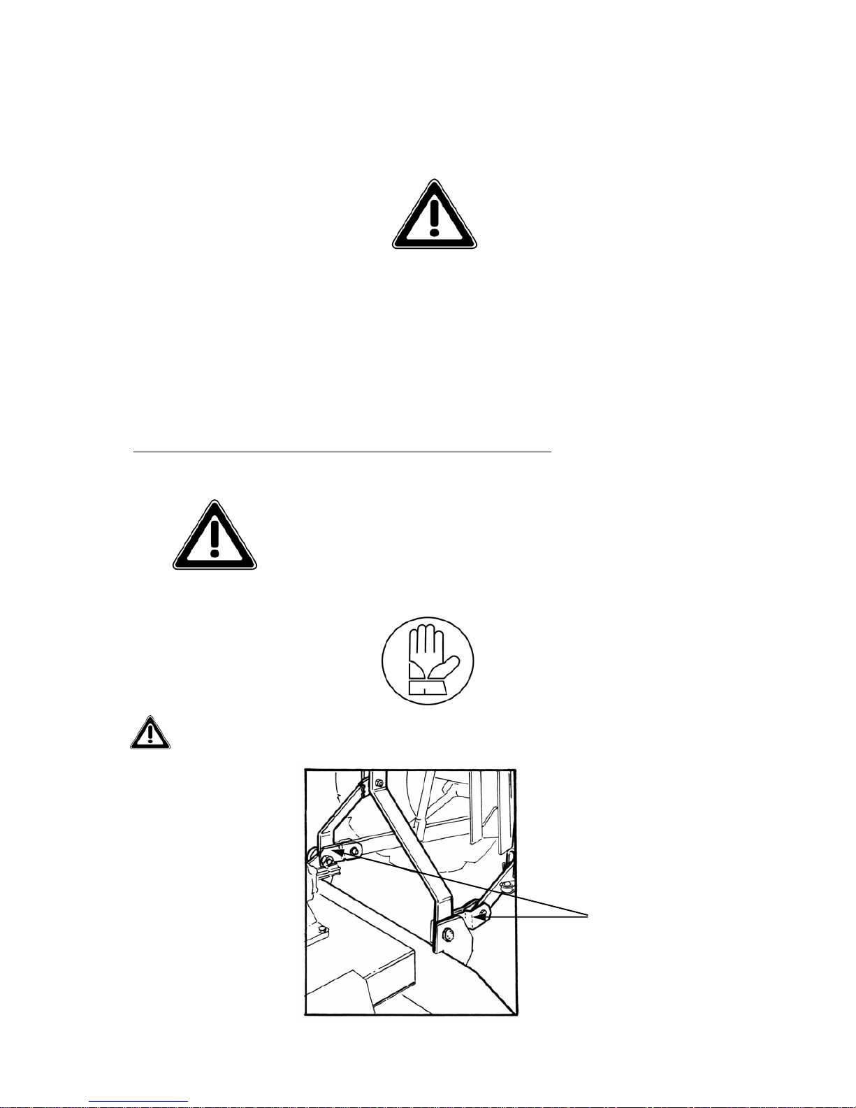
Do not allow anyone between tractor and implement when the
engine is running.
Follow these instructions:
Connect the hitch of the drawbar to the tractor using a hitch pin and the hair clip pin (see
fig. 1)
LOWER
PLATES
FIG. 1
Pag.12
Pag.13
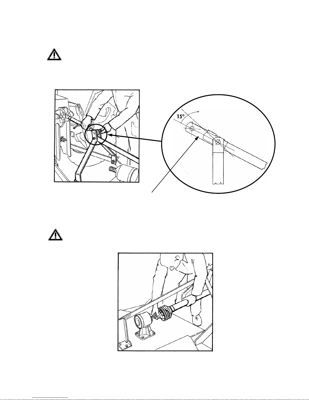
Connect the hitch point of the tractor to the floating upper plates of the machine using a
hitch pin and the hair clip pin (see fig. 2). This connection must guarantee a 15° inclina-
tion of the upper plates (see fig. 3) in order to let the machine adapt to the terrain and to
protect its frame from possible damage. The inclination is obtained by regulating the tie
rod of the hitch point of the tractor.
Connect the PTO shaft and be sure it is correctly connected to the tractor and the ma-
chine (see fig.4).
FLOATING UPPER
PLATES
FIG. 2 FIG. 3
FIG. 4
Pag.14
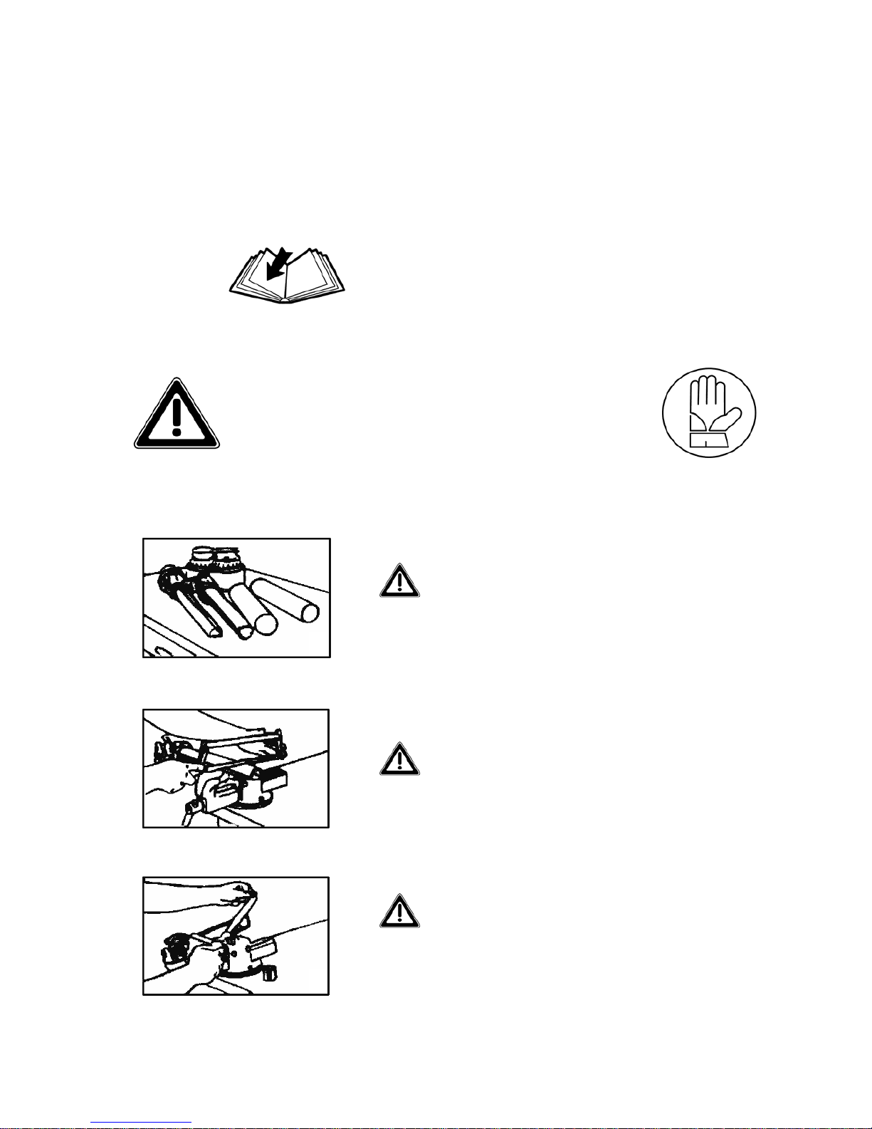
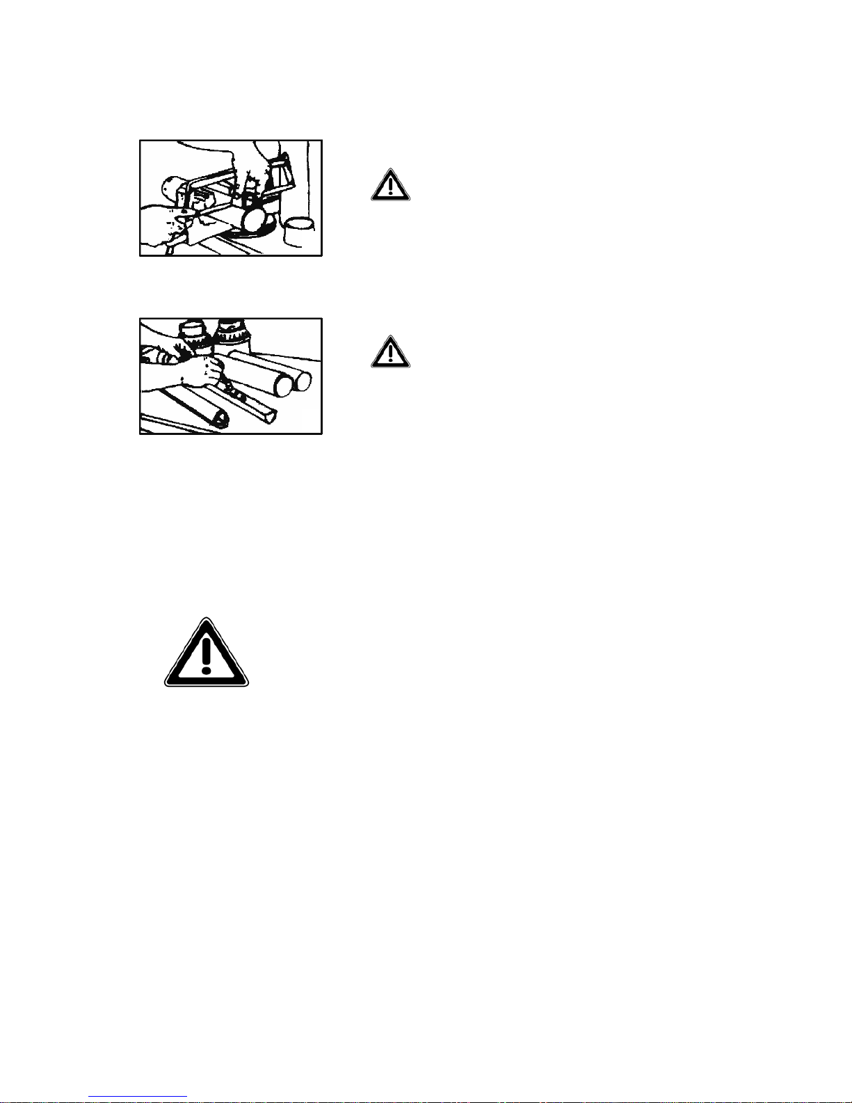
Shortening the PTO shaft
Due to the many different types of tractors, it may be necessary to shorten the PTO shaft.
Always refer to the manual of the driveline’s manu-
factures. Read it carefully.
In case shortening is needed, listed below are some basic guide-
lines on performing this modification. Determine how much
length is to be removed, then:
1) Remove plastic protection (both sec-
tions)
2) Cut the excess length of both tubes
3) Deburr and clean the saw-dust off ends
of tubes. Remove packing inside shaft
tubing
1
2
3
Pag.15
4) Cut the plastic protection to the same
length you have cut the joints
5) Grease the male joint section and reassem-
ble protection
Do not use PTO shafts without proper shielding installed.
4
5
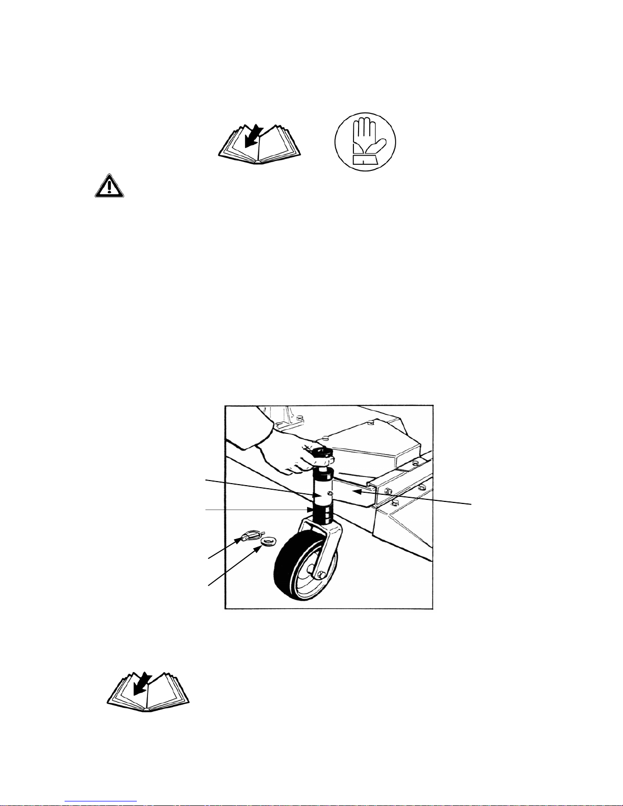
CUTTING HEIGHT ADJUSTMENT
To adjust the cutting height of your machine, follow the next instructions (see fig. 1):
• For each wheel unthread the split pin from the fork in which the cutting height regulation
spacers are threaded.
• If you wish to increase cutting height, add spacers under the bush of the support arms, for
each wheel.
• If you wish to reduce cutting height, add spacers over the bush of the support arms, for
each wheel.
• After concluding regulation as desired, insert the split pins in its respective forks.
To get uniformity on cut, the regulation described before
(by spacers) must be the same for the four wheels of the ma-
chine.
Pag.16
SUPPORT
ARSM
FIG. 1
BUSH
SPACERS
SPLIT PIN
WASHER
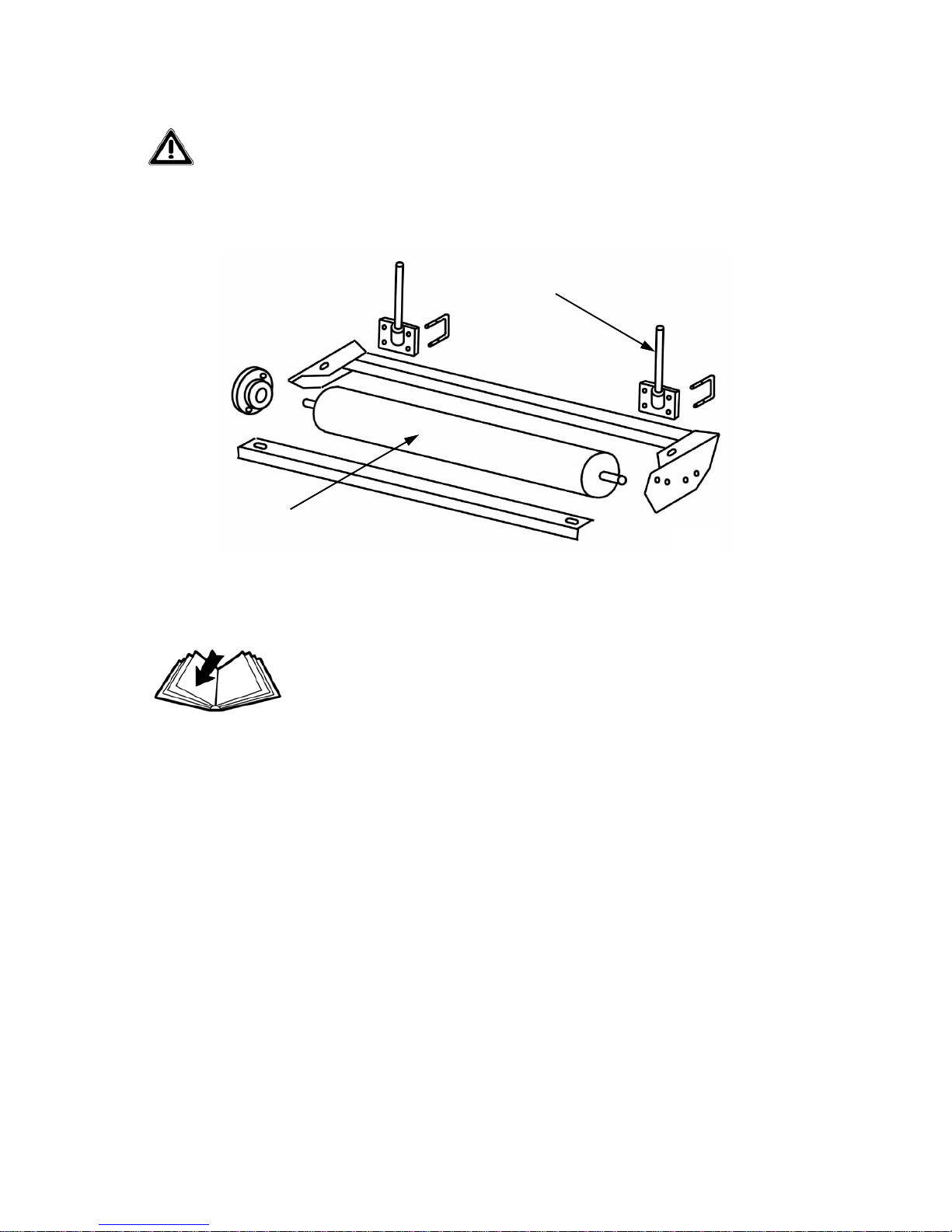
If your machine is equipped with a rear roller instead of the two wheels, the regulation is
carried out by unthreading the split pins from the forks of the two front wheels and from
the two frame-supports of the roller, to proceed by using the spacers, as explained before
(see fig. 2).
To get uniformity on cut, after regulating as explained before
(by rear roller), be sure the machine results parallel to terrain.
Minimum cutting height possible (following the two types of regulation) is 2,5 cm; the maxi-
mum possible is 12 cm.
REAR ROLLER FIG. 2
Pag.17
FRAME SUPPORT

BEGINNING WORK
After completing all safety controls, and being sure the machine is set out parallel to terrain (see
fig. 1), to avoid damage start as follows:
• Raise the machine off the ground in order to let the knives start moving without touching
ground.
• Maintaining the machine raised, engage the tractor PTO at suggested engine RPM.
• Start moving the tractor forward and then gradually lower the machine.
Cutting tips
Proper ground speed for cutting will depend upon the height, type and density of the grass to be
cut. However we suggest not to exceed 7 Km/h. Lower ground speed allows tall and dense grass
cutting. Taking a partial cut and/or reversing the direction of travel may also produce a cleaner
cut. Remember, sharp knives produce cleaner cuts and require less power.
To avoid damage to frame and gearbox as a consequence of im-
pact of the knives with soil or solid objects, it is advisable not
to carry out very low cuts.
Pag.18
Table of contents
Other Sovema Farm Equipment manuals


Popular Farm Equipment manuals by other brands


GREAT PLAINS
GREAT PLAINS PH-15 Operator's manual

Hoegger Home Farm Products
Hoegger Home Farm Products Milking System Training Series manual

APV
APV PS 800 M1 Translation of the original operating manual

LELY
LELY HIBISCUS 725 Master Operator's manual

MacDon
MacDon M105 2011 Operator's manual

HAYGAIN
HAYGAIN HG-GO user manual


