Sovema ERX-3 Series User manual

OPERATION & MAINTENANCE MANUAL Revision 2022
_____________________________________________________________________________________
CONTENTS - 1/1
CONTENTS
INTRODUCTION
I – GENERALITY
I.A – SYMBOLS
I.B – GENERAL INFORMATIONS
II – SAFETY
II.A – LABELS
II.B – RECOMMENDATIONS
III – OPERATION
III.A – C ECKLIST
III.B – TEC NICAL DATA
III.C – ITC ING
III.D – PREPARATION FOR WORK
III.E – USAGE
III.F – UN ITC ING
III.G – TROUBLES OOTING
IV – STORAGE
V – MAINTENANCE
VI – TOXICOLOGICAL INFORMATIONS
VII – DISPOSAL & RECYCLING
VIII – WARRANTY
8.A – TERMS & CONDITIONS
8.B – WARRANTY REGISTRATION
INDEX
ANNEX
A1 – EU DECLARATION OF CONFORMITY
A2 – SOVEMA PRODUCT RANGE
A3 – SPARE PARTS CATALOGUE

OPERATION & MAINTENANCE MANUAL Revision 2022
____________________
____________________
____________________
____________________
_____
INTRODUCTION - 1/1
INTRODUCTION
Dear Owner,
thank ou for bu ing a SOVEMA product.
Your new implement has been carefull designed and manufactured to give ou excellent
performance and dependable service, if properl operated and maintained.
Do not use the implement for operations far from the “intended use” of the manufacturer.
You will find this implement to be stead and reliable when matched to the suggested
tractor power.
Much time has been invested in providing safet and protection. Read carefull the present
manual, giving guidance for the correct, safel and easil , use and routine basic
maintenance of implement. Moreover, it contains warnings for foreseeable hazards as well
as definitions of terms, s mbols and pictograms used compl with the relevant international
standard. Keep manual for future reference.
Be sure that ou and an other operator carefull follow the recommended safet practices
at all times. Failure to do could result in personal injur or propert damage.
Of course, if ou should have an problems or questions, please do not hesitate to contact
our local SOVEMA dealer or, alternativel , to contact us at the addresses or numbers
indicated in this manual.
The reproduction in whole or in part of this manual is prohibited without prior written
agreement with SOVEMA.
SOVEMA manufactures a wide variet of agricultural equipment. If ou are interested in
discovering our entire range, please contact us.
Thanks for our choice.
Pier Silvio Ma er
President
OPERATION & MAINTENANCE MANUAL Revision 2022
____________________
____________________
____________________
____________________
_____
I - 1/2
I - GENERALITY
The manual is the translation of the ori inal manual in italian lan ua e (official lan ua e).
If you should notice any unclear points, omissions, etc., feel free to contact SOVEMA.
I.A - SYMBOLS
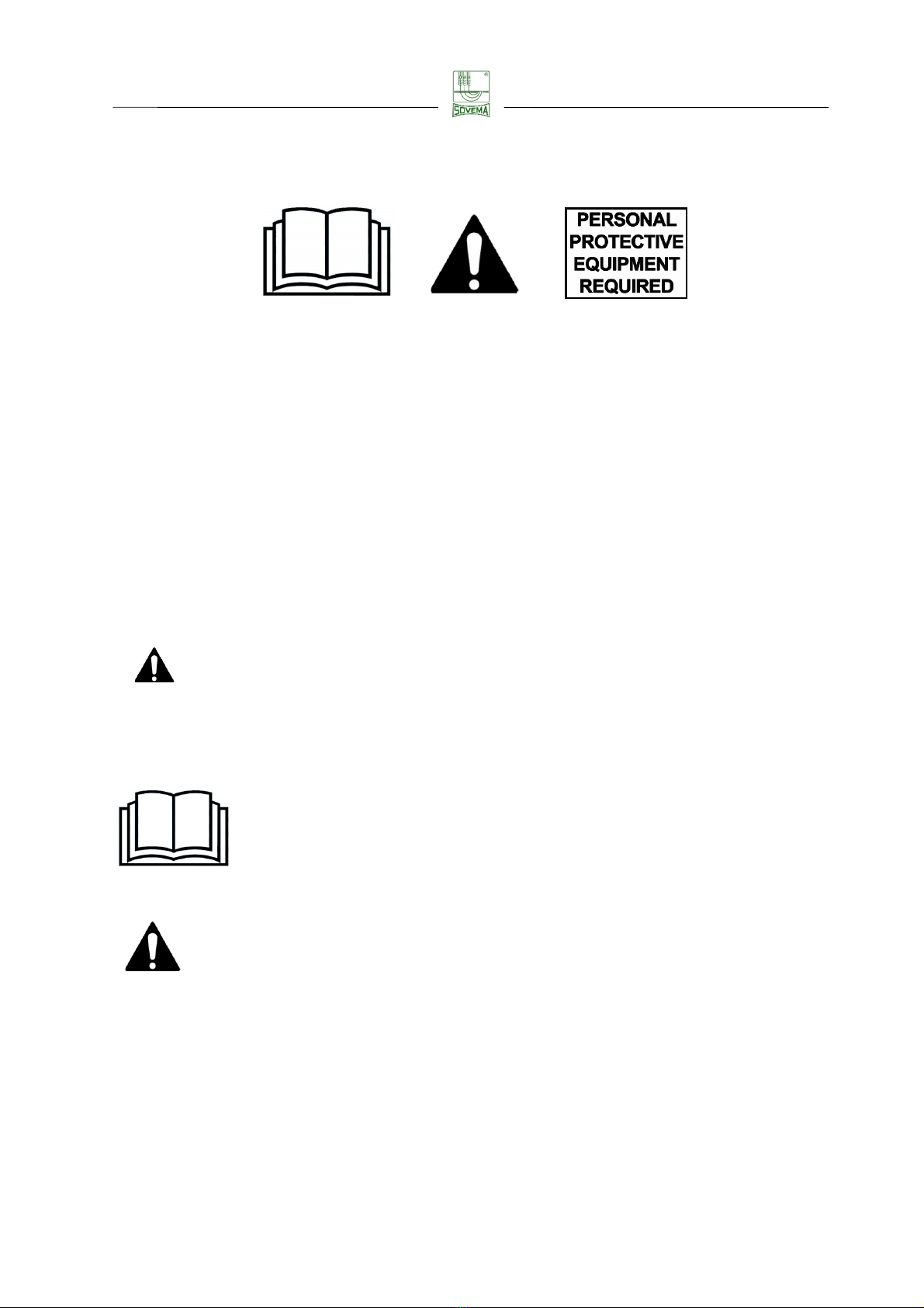
These followin safety picto rams appear throu hout the manual.
Remember their meanin .
READ CAREFULLY!
YOUR SAFETY IS IN DANGER!
USE PERSONAL PROTECTIVE EQUIPMENT!
(safety shoes, protective loves, helmet, o les, overalls and FFP1 mask)
IMPORTANT INFORMATION!
OPERATION & MAINTENANCE MANUAL Revision 2022
_____________________________________________________________________________________
I - 2/2
I.B - GENERAL INFORMATIONS
All implements with movin parts are potentially hazardous. The manufacturer has desi ned
the implement to be used with all the uards properly fitted.
The purpose of this manual is to provide important informations on technical specifications,
safety, operatin , maintenance and troubleshootin of the implement, so you can use it in a
proper, safe and efficient way. Compliance with this manual contributes to avoid risks,
reducin repair costs and downtime and increasin the reliability and lifetime of the
implement.
This manual have been filled in by our decennial experience. Followin the instructions, you
should be able to develop operatin procedures suitable to your needs.
The ima es contained in this manual are indicative and may differ from reality, their purpose
is illustrative only.
Illustrations used in this manual may vary sli htly in some details compared to your
implement.
Even if some illustrations in this manual could show the implement with safety uards
removed for a better understandin , never operate in these conditions.
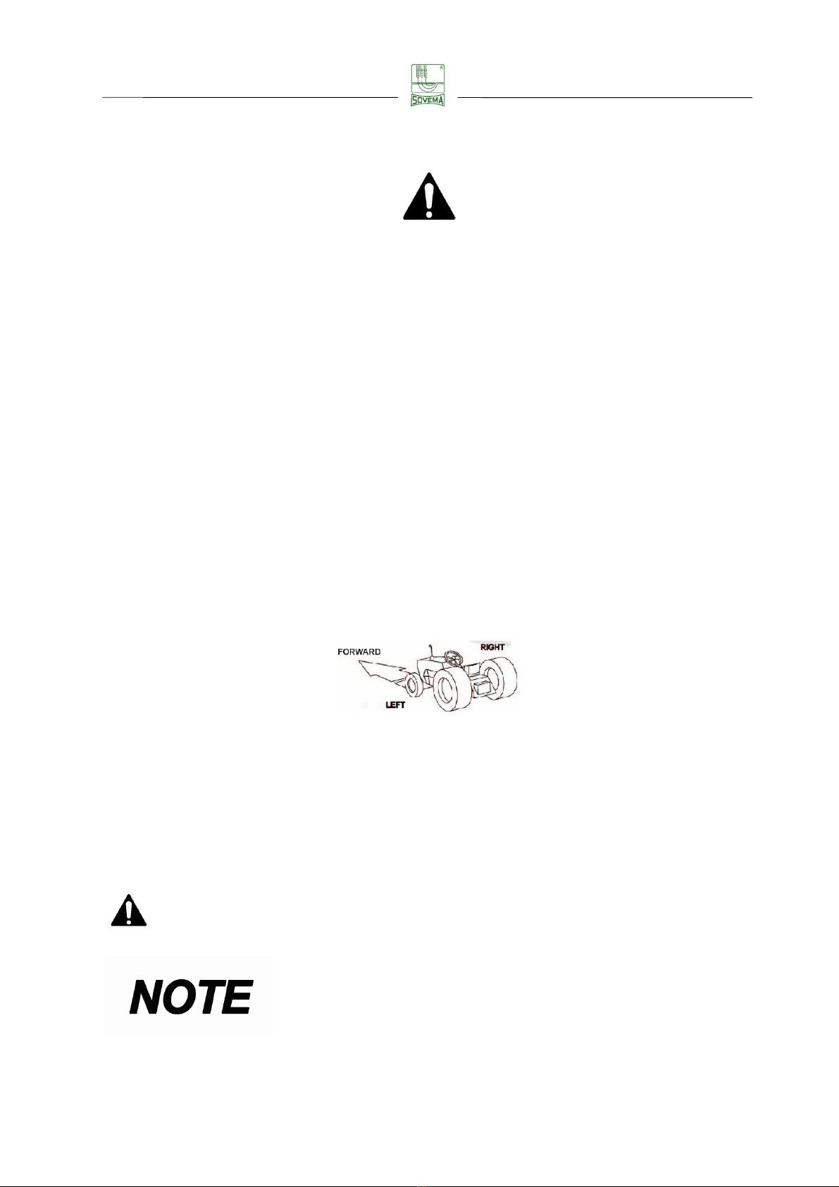
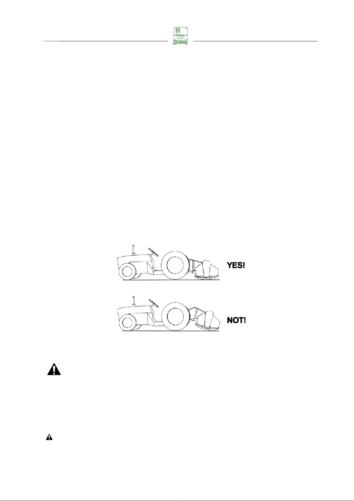
In this manual references to “forward”, “ri ht” and “left” are referred as indicated in ima e
below, with the implement connected to the tractor on its rear three-point hitch.
FIELD OF USE : The implement must be used for a ricultural activities. The operator, on the
basis of workin conditions always available, must pay particular attention to the
performance limits of the implement. At the first si n of overloadin , the implement must be
stopped immediately.
This manual is protected under copyri ht law. Any reproduction and distribution, partial or
complete, of document is not permitted unless expressly permitted in writin .
BEFORE OPERATING THE IMLEMENT ALL SAFETY GUARDS MUST BE
MOUNTED!
KEEP THE MANUAL IN A
SAFE AREA FOR ALL OF LIFE OF
THE IMPLEMENT. IF IT IS PARTIALLY RUINED OR LOST YOU
HAVE TO REQUEST A NEW ONE CONTACTING A DEALER
SOVEMA OR SOVEMA ITSELF.
OPERATION & MAINTENANCE MANUAL Revision 2022
____________________
____________________
____________________
____________________
_____
II - 1/6
II – SAFETY
This section is very important ecause even if the implement is well-designed and even if
safety guards are present on the implement, residual risks remain and the operator have to
know them in order to avoid injuries.
II.A - LABELS
Safety pictograms (hereafter decals), placed in a visi le position on the implement contain
important safety warnings. To prevent injuries the operator have to read and understand
them carefully and keep them clean and visi le.
Check that all the decals are on the implement and in a good condition. If not, do not use the
implement without decals and refer to the dealer immediately to get them.
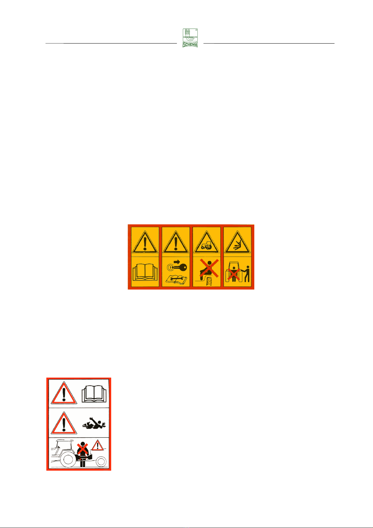
The meaning of decals that are on the implement is the following:
1 2 3 4
1
Before starting operations, read carefully the instruction manual
2
Before performing the maintenance, lower the implement to the ground, turn off
the engine, disengage the PTO and read the operator manual
3
People, animals or o jects must never e transported on wrong place of the
tractor or of the implement, fatal injuries may occur
4
Do not stand ehind the tractor during operations
5
Before connecting the implement to the PTO, read
carefully the operation & maintenance manual
6
Hazard of entanglement in PTO drive shaft
7
Keep away from the PTO drive shaft in operation: the
contact can cause death

OPERATION & MAINTENANCE MANUAL Revision 2022
____________________
____________________
____________________
____________________
_____
II - 2/6
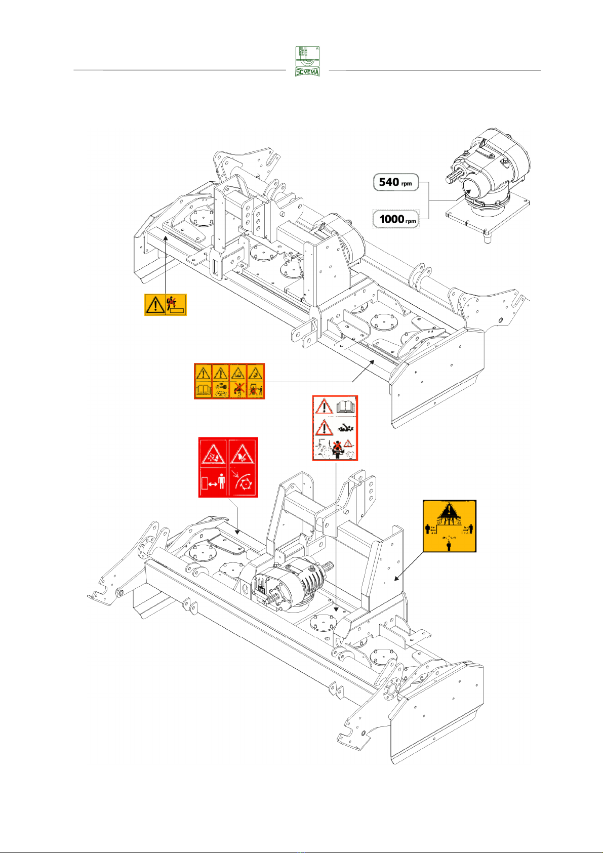
8 9 10 11
8 Hands and feet can e injured y moving tines. Keep away from the
implement
9 Your feet can e injured. Keep away from the implement
10 Your hands can e injured. Do not remove safety guards and keep away from
moving parts
11 Your hands can e injured. Do not remove the cover and keep away from
moving parts
The implement is designed for 540 rpm PTO
The implement is designed for 1000 rpm PTO
During working operations all ystanders must stay
eyond the shown distances from the implement
Do not step or stand on this surface
OPERATION & MAINTENANCE MANUAL Revision 2022
____________________
____________________
____________________
____________________
_____
II - 3/6
In the following figure it is indicated the location of decals descri ed a ove.

OPERATION & MAINTENANCE MANUAL Revision 2022
____________________
____________________
____________________
____________________
_____
II - 4/6
II.B - RECOMMENDATIONS
Before using the implement you must e sure to know the main safety recommendations;
many accidents are caused y not o serving these simple rules.
SOVEMA Srl declines to the full extent allowed y the applica le laws all lia ility and
responsi ility for any damages of any kind resulting from the non-o servance of the rules
and guidelines expressed in this manual
PRE-OPERATIONAL AND OPERATIONAL SAFETY RULES
This manual must e always availa le and should e read and studied y any person
who is authorized to work with the implement
Keep all guards and safety decals in place and in a good condition efore operating
the implement. Guards can e removed for maintenance or cleaning purpose only
Only operate with a tractor equipped with an approved Roll Over Protective System
(ROPS) and always fasten seat elt
Operate with daylight or good artificial light only
Be sure that only trained personnel operate/maintain the tractor the implement
Personal protection equipment, including overalls, safety shoes, goggles, helmet,
gloves and mask are recommended during the operations of
hitching/usage/unhitching of implement
Do not leave seat until the implement is lowered to the ground, engine is completely
turned off, rakes engaged, ignition key removed
Do not allow to other people to stay on wrong place of the tractor or on implement at
any time
Before starting operations, make sure that the tractor PTO is set to match the PTO
requirements of implement. The speed is indicated on the implement and in this
manual on “III.B - TECHNICAL DATA” section
Always use the PTO drive shaft supplied y the manufacturer
Make sure that the PTO drive shaft is firmly connected to the tractor and
to the
implement and locked in position
For hitching and unhitching the PTO drive shaft, please refer to the manufacturer’s
instructions manual and to your tractor’s instructions manual
Hitching and unhitching of the PTO drive shaft must e performed with the tractor’s
engine turned off
Keep hands, feet, long hair, loose clothing and jewelry away from moving parts
To prevent injury y thrown o jects do not operate unless all personnel, livestock
and pets are 20 m (65 ft) away

OPERATION & MAINTENANCE MANUAL Revision 2022
____________________
____________________
____________________
____________________
_____
II - 5/6
The rotating parts of the implement have een designed and tested for rugged
use. However they can damage due to impact with heavy solid o jects. Such
impact can cause fragments to e thrown outward at very high speed. To reduce
the possi ility of serious injury, or even death, never allow the rotating parts to go
to the contact with such o stacles
Stop the implement and tractor immediately upon hitting an o stacle. Turn off the
engine, remove the ignition key, inspect and repair any damage efore resuming
operation
No repairs or adjustments should e carried out while the implement is connected
to the tractor and turned on
Disengage tractor PTO and place transmission into neutral position efore
attempting to start tractor engine
USE AFTER A LON PERIOD OF INACTIVITY
Before using the implement after a long period of inactivity, please follow these steps:
Make sure the implement is not damaged
Check all mechanical parts. They must e in good condition and must not show
signs of rust
Check wear of tools
Verify that the implement does not present loss of oil from couplings or tu es
Lu ricate all moving parts
Verify that all safety guards are correctly positioned and assem led
Verify that all safety decals are correctly positioned and assem led
ROAD TRANSPORT SAFETY
Plan route to avoid heavy traffic
Make sure that all moving parts e firmly secured
Be sure that the implement is in the raised position for transport
When you drive never drink
Pay attention to traffic when operating near or crossing roadways
Drive at low speed to avoid ouncing and loss of steering control
Before transportation, remove any dirt, soil, crop residue or other elements that
might e dangerously dispersed during transport

OPERATION & MAINTENANCE MANUAL Revision 2022
____________________
____________________
____________________
____________________
_____
II - 6/6
Before transportation, pay particular attention to the integrity of the coupling pins
and to the presence of their safety pins
In case of transport on pu lic roads, o serve the traffic code of the State where the
implement is, pay particular attention to the requirements relating to the visual
signalling devices, to the overall dimensions and the admitted weight
MAINTENANCE SAFETY
Good maintenance is your responsi ility. Poor maintenance is an invitation to fault
Please follow these common practices:
1. keep service area clean
2. use adequate illumination for the working place
3. make sure the electric tools are properly grounded
4. make sure the service area is properly ventilated
Before performing maintenance of implement, e sure that area is level, turn off the
engine, disengage the PTO, lower the machine, engage the rakes and remove the
ignition key
Keep all people away from the service area while performing maintenance
Always use personal protective equipment included, esides safety shoes and
protective gloves, overalls, goggles, and helmet
When replacing a mechanical part, always use original spare parts in order not to
compromise the implement and your own personal safety. SOVEMA assumes no
lia ility if the replacement of non original parts is performed
After servicing, e sure that all safety guards are re-installed properly
After servicing, make sure that all safety decals are reinstalled on the implement
and in good condition
If the implement is modified from the original design, no responsi ility for the
manufacturer can e claimed
In case of lifting of the implement the operator have to use the lifting holes indi-
cates in this manual on “V - MAINTENANCE” section

OPERATION & MAINTENANCE MANUAL Revision 2022
____________________
____________________
____________________
____________________
_____
III.A - 1/1
III – OPERATION
III.A – CHECKLIST
Before connecting the im lement to the tractor, lease read the following instructions:
Make sure that the weight and ower of the tractor is suitable to the im lement you
want to connect. If you have any doubt, lease refer to the “III.B – TECHNICAL
DATA” section
Make sure that all safety ictograms (decals) are ro erly installed and clean
Check the oil level in the gearbox. A low oil level can damage the gears
Make sure that all safety guards are ro erly installed and in good condition

OPERATION & MAINTENANCE MANUAL Revision 2022
____________________
____________________
____________________
____________________
_____
III.B - 1/1
III.B - TECHNICAL DATA
The implement descri ed in this manual is a fixed rotary harrows from the ERX-3 series.
The identification plate is located on the right-upper side of implement frame.
The image shown is for illustrative purpose only
MODEL
WORKING
WIDTH
POWER WEIGHT
WIDTH
“A”
DEPTH
“B”
HEIGHT
“C”
cm/in
hp/kw
kg/l
cm/in
cm/in
cm/in
ERX
-
3 200
200/79" 60÷80/44÷59 890/1960 214/84" 135/53" 123/48"
ERX
-
3 250
250/98" 70÷90/51÷66 995/2191 264/104" 135/53" 123/48"
ERX
-
3 300
300/118"
80÷100/59÷74
1135/2500
314/124"
135/53"
123/48"
MODEL HITCH
CAT.
WORKING
DEPTH
NO. ROTORS
NO TINES (RH + LH)
THREE-POINT HITCH
POSITION
COMPARED TO RAME
SX
DX
cm/in
no.
–
no.
cm/in
ERX
-
3 200
II 29/11" 8 - 16 (8 RH + 8 LH) 100/39" 100/39"
ERX
-
3 250
II 29/11"
10 - 20 (10 RH + 10 LH) 125/49" 125/49"
ERX
-
3 300
II 29/11"
12 - 24 (12 RH + 12 LH) 150/59" 150/59"
PTO
SPEED
GEARBOX RATIO ROTORS SPEED
rpm no. no. rpm
540 26 31 220
540 31 26 310*
1000
26
31
405
NOISE LEVEL UNDER NO LOAD
*in order to operate with this speed follow the instructions indicated on “III.D-PREPARATION FOR WORK” chapter
B
A
C

OPERATION & MAINTENANCE MANUAL Revision 2022
____________________
____________________
____________________
____________________
_____
III.C - 1/3
III.C HITCHING
The implement descri ed in this manual can e connected to any kind of tractor provided of
universal three-point linkage.
The characteristics of this linkage depend on the type of tractor, therefore it is necessary to
setting up the tractor in order to properly connect the implement.
This operation must e carried out on a flat and firm area as it is dangerous.
Do not allow anyone to stay etween tractor and implement while the engine is
running
Follow these instructions:
1. Connect the tractor two lifting arms to the lower plates of the implement y using two
hitch pins and two cotter keys to lock pins in place (see Fig. 1)
Figure 1
2. Connect the tractor top link to the mast of implement y using hitch pin and a cotter
key to lock pin in place (see Fig. 1)
MAST
LOWER PLATES
OPERATION & MAINTENANCE MANUAL Revision 2022
____________________
____________________
____________________
____________________
_____
III.C - 2/3
3. Lift up the implement off the ground
4. While remaining in the driving seat, put the tractor PTO in neutral position
5. When the PTO drive shaft has completely stopped, turn off the engine, engage the
parking rake and remove the ignition key
6. Get off the tractor and place wheels in a desired working position y using the
ru er ushes
7. Connect the PTO drive shaft to the implement
8. Connect the PTO drive shaft to the tractor. If the shaft is too long you have to
shorten it, please refer to the instructions on the next page
9. (if present) Connect implement hydraulic hoses to the tractor distri utor
10. Get on the tractor, insert the ignition key and turn on the engine
11. Lower the implement and adjust it so that it is parallel to the ground. Do this y
adjusting the tractor top link (see Fig. 2). This will improve the life-span of the
implement and the PTO shaft
Figure 2
Always check that the tractor PTO is in neutral position efore connecting the
PTO drive shaft!
NOTE ON THE PTO DRIVE SHAFT
Always refer to the manufacturer’s instructions manual.
Read it carefully
!

OPERATION & MAINTENANCE MANUAL Revision 2022
____________________
____________________
____________________
____________________
_____
III.C - 3/3
Shorten the PTO drive shaft
Due to the many different types of tractors, it may e necessary to shorten the PTO shaft.
Listed elow are some asic guidelines on performing this modification. First, determine
the length that has to e removed
1) remove plastic protection on oth sections
2) cut the excess length of oth tu es using a saw
3) de urr and clean the ends of each tu e
4) cut the plastic protections to the same length you have cut the tu es
5) grease the the tu e and reassem ly the drive shaft

OPERATION & MAINTENANCE MANUAL Revision 2022
____________________
____________________
____________________
____________________
_____
III.D - 1/1
III.D - PREPARATION FOR WORK
Working depth adjustment
In order to set up the implement s working depth, adjust the rear roller actuating the
hydraulic cylinders, as indicated in figure 1 :
Figure 1
After adjusting the rear roller it is necessary to adjust the position of the levelling bar as
follows (see figure 2):
unblock the screw register crank of the levelling bar by taking out the stop of the crank
itself
rotate the crank until the levelling bar reaches the desired position
block the crank using the stop
Figure 2
In order to obtain an even soil, for each wheel, please adjust the two supports at
the same height.
CYLINDER
CYLINDER
REGISTER SCREW
CRANK
OPERATION & MAINTENANCE MANUAL Revision 2022
____________________
____________________
____________________
____________________
_____
III.E - 1/1
III.E - USAGE
After having com leted all safety checks and made sure the harrow is arallel to the
ground, roceed as follows:
• raise the im lement off the ground in order to let the tines start moving without
touching ground to avoid damages
• kee ing the im lement raised, engage the tractor PTO at suggested engine’s revs
• start moving the tractor forward and then gradually lower the im lement
OPERATING TIPS
Pro er ground s eed for harrow will de end u on the ty e of soil and its
conditions. However we suggest not to exceed 5 km/h (3.1 m h)
Lower ground s eed allows to grind the soil with better erformance. In order to obtain a
o osite result roceed more quickly
During the o eration, in order to not cause damages to the harrow,
avoid to steer the im lement and avoid to work in reverse. It is always
necessary to raise the im lement before making a turn or change of
course, otherwise damages to the skid or roller su orts can occur.
The im lement must be used only if equi ed with all its com onents as
su lied by SOVEMA (safety devices included). No com onents can be
modified

OPERATION & MAINTENANCE MANUAL Revision 2022
____________________
____________________
____________________
____________________
_____
III.F - 1/1
III.F – UNHITCHING
The disconnection of the implement f om the t acto must be ca ied out on a flat and fi m
su face. It’s a dange ous ope ation, pay attention. Please ead the following inst uctions
ca efully:
1. Once eached the pa king position, while emaining in the d iving seat, put the
t acto PTO in neut al position
2. When the PTO d ive shaft has completely stopped, tu n off the engine, engage the
pa king b ake and emove the ignition key
3. Get off the t acto and place the ea olle in a desi ed position
4. Get on the t acto , inse t the ignition key, tu n on the engine and lowe the
implement on the g ound (check that tines and ea olle co ectly and fi mly est on
the g ound)
5. (if p esent) Disconnect implement hyd aulic hoses f om t acto dist ibuto and place
them in thei holde s o inse t the plug on each hose end
6. Remove PTO d ive shaft f om the t acto
7. Remove PTO d ive d ive shaft f om the implement
8. Disconnect the t acto top link then
9. At the end, p oceed disconnecting the t acto two lowe links
Always check that the t acto PTO is in neut al befo e disconnecting the PTO
d ive shaft

OPERATION & MAINTENANCE MANUAL Revision 2022
____________________
____________________
____________________
____________________
_____
III.G - 1/3
III.G TROUBLESHOOTING
During the operation o implement several problems can happen:
UNUSUAL NOISES
During working, i the implement produces unusual noises, the operator must
immediately stop it and ollow these instructions:
• Make sure that there are no broken/bent mechan cal parts
• Check that the gearbox conta ns the correct amount of o l
I the oil level is too low (please see the section “V - MAINTENANCE”), the gears
are not adequately lubricated and i the gearbox continues to rotate will determine
a signi icant increase in oil temperature. This will quickly produce damages to the
gears and bearings
• Check t nes cond t ons
I some o the tines are broken, bent or present excessive wear, the balance o
the rotor will be compromised. During working, the rotating movement o the rotor
will produce vibrations that will inevitably damage and break bearings and welded
parts o the rame. In order to avoid damages, please replace all the tines at the
same time with the new genuine ones supplied by SOVEMA
• Check the lubr f cat on of the gears conta ned n the box
As a consequence o inadequate lubrication, damage to some gears can occur in
short time. Continuing to work in this way can occur the block o the transmission
in short time
• Check the lubr cat on and cond t on of the rotor shafts bear ngs
As a consequence o reduced lubrication, one or both the bearings supporting the
rotor sha t may have broken down. The rotor begins to oscillate producing
excessive vibrations against the rame, producing damages to the welded parts
o the rame

OPERATION & MAINTENANCE MANUAL Revision 2022
____________________
____________________
____________________
____________________
_____
III.G - 2/3
Another possible cause or breaking rotor sha t bearings can be the impact with
heavy objects on the ground such as stones, metallic objects, etc.
Another possible cause or breaking rotor sha t bearings is the improper use o
the implement; esplecially using it at high speed, changes on direction, u-turns
while working
• Check the mplement
During the working i the implement jumps over the soil or vibrates may be that
tines mounting is incorrect or blunt edges o tines are penetrating the soil irst
WORKING ANOMALIES
I a ter the operation the implement ailed to obtain an acceptable tillage, the operator must
ollow these instructions:
• Check t nes
The tines can be worn and less e ective. Please replace them. Use original tines
SOVEMA only.
During the working i the the tines rub along the soil instead o penetrating it,
please advance more slowly.
During the working i the tines are clogged raise the levelling bar in order to keep
clods away the tines
• Check f the work ng depth has been properly set up
The adjustment o the implement may be uneven. Check that roller is parallel to
the soil
• Check gears cond t on after remov ng the frame l d
It is possible that the gears are not in good condition, thus ailing to transmit
enough power to the tines.
I a gear looks marginally damaged, the operator must replace it immediately
• Check f rotors are free from fore gn bod es
It is possible that objects, such as clods, stones, metal parts etc., are attached to
the rotor sha ts or tines prevent it works in the best condition. I it is happened this
above mentioned please remove the oreign parts
• Check advancement tractor speed
A less-than-adequate result can be produced by an incorrect working speed. The
speed must be set up in relation to the rotor turns, type o soil and tractor power.
Advancing too quickly doesn’t allow the tines to grind thoroughly
This manual suits for next models
3
Table of contents
Other Sovema Farm Equipment manuals


