Sovema BTH 250 User manual

INSTRUCTION MANUAL Page 1 Revised 2013
Dear Owner,
Thank you for buying a SOVEMA manufactured product.
Your new machine has been carefully designed and manufactured to give you superior
performance and dependable service, if properly operated and maintained.
You will find this machine to be rugged and reliable when matched to the suggested
horsepower operating range.
Much time has been invested in providing safety and protection. Please carefully read
this manual. It tells you how to safely and easily assemble, operate and maintain your
machine.
Be sure that you and any other operator carefully follow the
recommended safety practices at all times. Failure to do so could result in personal injury
or property damage.
Of course, should you ever have any problems or questions, please contact your local
SOVEMA dealer or contact us at the addresses or numbers indicated in this manual.
SOVEMA manufactures a variety of innovative equipment. If you are interested in
reviewing our full line, please contact us.
Thanks for your choice.
Pier Silvio Mayer
President

INSTRUCTION MANUAL Pag. 2 Revised 2013
TABLE OF CONTENTS
SYMBOLS ..................................................................................................................... 3
GENERAL INFORMATION ........................................................................................... 4
SAFETY DECALS ......................................................................................................... 5
SAFETY INSTRUCTIONS............................................................................................. 7
MAIN CHECKS.............................................................................................................. 10
TECHNICAL SPECIFICATIONS ................................................................................... 11
HITCHING THE MACHINE............................................................................................ 12
CUTTING HEIGHT REGULATION................................................................................ 14
OPERATING THE IMPLEMENT ................................................................................... 16
TROUBLESHOOTING................................................................................................... 18
DISCONNECTING THE MACHINE............................................................................... 20
STORAGE ..................................................................................................................... 21
MAINTENANCE............................................................................................................. 23
SPARE PARTS LIST ..................................................................................................... 29
LIMITED WARRANTY POLICY..................................................................................... 40
SOVEMA PRODUCT LINE............................................................................................ 44
DECLARATION OF COMPLIANCE CE ........................................................................ 47
INSTRUCTION MANUAL Page 3 Revised 2013
SYMBOLS
These symbols appear throughout the manual.
Remember their meaning and advice.
CAUTION!
YOUR SAFETY IS IN DANGER!
READ CAREFULLY
USE PROTECTIVE GLOVES
INSTRUCTION MANUAL Page 4 Revised 2013
GENERAL INFORMATION
All implements with moving parts are potentially hazardous. The manufacturer has
designed the implement to be used with all the safety equipment properly attached. The
purpose of this manual is to assist you in safely maintaining and operating the implement.
These instructions have been compiled from our experience.
By following these instructions, you should be able to develop operating procedures
suitable to your needs.
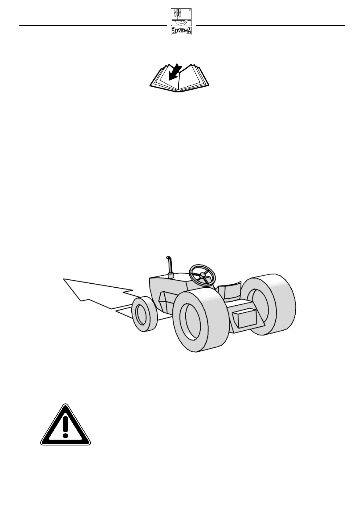
Illustrations and data used in this manual may vary slightly in some details. Throughout
this manual references are made in left and right directions. These are determined by
standing at the rear of the equipment and facing the direction of advancement.
Even if some illustrations in this manual show the machine
with safety shields removed for a better view, never operate
in these conditions.
BEFORE OPERATING THE IMPLEMENT, ALL SAFETY
SHIELDS OR DEVICES MUST BE MOUNTED!
RIGHT
LEFT

INSTRUCTION MANUAL Page 5 Revised 2013
SAFETY DECALS
Safety decals on the implement contain important safety warning messages. To prevent
injuries we invite the operator to read them carefully and keep them clean.
Check that all the decals are on the machine. If not, DO NOT USE the machine and
report to the Dealer immediately to get the decals.
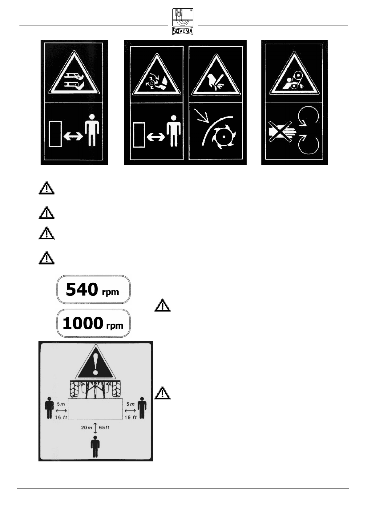
Decals on the machine are as follows:
1 2 3 4
1Before beginning operations, read carefully the instruction manual.
2Before maintenance operations, lower the implement to the ground, shut off
the engine, disengage the PTO and read the instruction manual.
3Do not allow riders on the tractor or implement., fatal injuries may occur.
4Do not stand behind the tractor during operations.
5Before attaching the implement to the PTO, read the
instruction manual carefully.
6Danger of entanglement to the PTO shaft.
7KEEP AWAY from the PTO shaft in operation: con-
tact can cause death!
INSTRUCTION MANUAL Page 6 Revised 2013
8 9 10 11
8Danger. Hands and feet can be injured by moving knives. Keep away from
the implement.
9Danger. Your feet can be injured. Keep away from the implement.
10 Danger. Your hands can be injured. Do not remove safety protection and
keep away from moving parts..
11 Danger. Your hands can be injured. Do not remove the cover and keep away
from moving parts.
12 The machine is designed to be used on
tractors with 540 or 1000 RPM PTO .
13 Caution! During working operations all by-
standers must stay beyond the shown dis-
tances from the implement.

INSTRUCTION MANUAL Page 7 Revised 2013
SAFETY INSTRUCTIONS
Before using the implement you must be sure to know the main safety precautions; in fact
many accidents are caused by not observing these simple rules.
Sovema S.r.l. declines to the full extent allowed by the applicable laws all liability
and responsibility for any damages of any kind resulting from the breach of the
rules and guidelines expressed in this manual
PRE-OPERATIONAL AND OPERATIONAL RULES.
• Make sure that no one operates the machine unless they have first thoroughly
read and studied this instruction manual and understood all the safety
precautions.
• Keep all guards, shields and safety decals in place and in proper working order
before operating the machine.
• Only operate with a tractor equipped with an approved Roll Over Protective
System (ROPS) and always wear your seat-belt.
• Operate only in daylight or good artificial light.
• Only trained personnel shall operate the tractor and the implement.
• Personal protection equipment, including safety shoes, safety glasses, hard hat
and gloves are recommended during the different operations. Do not allow long
hair, loose fitting clothing or jewellery to be around moving parts.
• Do not leave the seat until the engine is completely turned off, brakes
locked and ignition key removed.
• Do not allow riders on the machine or tractor at any time..
• Before starting operations, make sure that the tractor's PTO is set to match the
PTO requirements of the implement. The speed is indicated in this manual and
on the implement.
• Always use the PTO shaft supplied by the manufacturer

INSTRUCTION MANUAL Page 8 Revised 2013
• Make sure the PTO shaft is firmly attached to the tractor and the implement and
that the locking pins have snapped shut.
• To connect and disconnect the PTO shaft, please refer to the manufacturer’s
instruction manual and to your tractor’s instruction manual.
• Connection and disconnection of the PTO shaft must be performed with the
tractor’s engine turned off.
• Keep hands, feet, hair and clothing away from moving parts
• To prevent injury by thrown objects DO NOT operate unless all personnel,
livestock and pets are 20 m (65 ft) away.
• The rotating parts of the machine have been designed and tested for rugged
use. However they can fail upon impact with heavy solid objects. Such impact
can cause fragments to be thrown outward at very high speed. To reduce the
possibility of serious injury, or even death, never allow the rotating parts to
contact such obstacles.
• Stop the machine and tractor immediately upon hitting an obstruction. Turn off
the engine, remove the key, inspect and repair any damage before resuming
operation.
• No repairs or adjustments should be attempted while the machine is attached to
a tractor that is turned on.
• Disengage tractor PTO and place transmission into neutral before attempting to
start engine.
TRANSPORT SAFETY
• Plan your route to avoid heavy traffic.
• For public roads, comply with state and local safety and movement rules.
• Be sure that the implement is in the raised position for transport.
• When you must drive, do not drink.
• Pay attention to traffic when operating near or crossing roadways.
• Reduce speed when transporting mounted implement to avoid bouncing and
loss of steering control.
MAINTENANCE SAFETY
• Good maintenance is your responsibility. Poor maintenance is an invitation to
trouble.
•Please follow these common practices:
- keep service area clean;
- make sure the area is well lit;
- make sure the tools and the electric appliances are properly grounded;
- make sure the service area is properly ventilated.

INSTRUCTION MANUAL Page 9 Revised 2013
• Before performing maintenance on this machine, drive to a level area, turn off
the engine, disengage the PTO, lower the machine, set the brakes and remove
the ignition key .
• Keep all persons away from the service area while performing maintenance.
•Always use personal protection devices.
• Periodically tighten all bolts, nuts and screws.
• When replacing a mechanical part, always use original spare parts in order not
to compromise the machine and your own safety. The implement manufacturers
assumes no liability if replacement parts other than originals are used.
• After servicing, be sure that all safety shields are re-installed properly.
• Make sure that all safety decals are installed, clean and in good condition.
• If the machine is modified from the original design, no responsibility for the man-
ufacturer can be claimed.

INSTRUCTION MANUAL Page 10 Revised 2013
MAIN CHECKS
Before connecting the machine to the tractor, read the following instructions:
• Make sure the weight and power of the tractor is correct for the machine you want to
connect. If you have any doubt, refer to the technical specifications.
• Ensure that all safety decals are properly installed and clean.
• Check oil in the gearbox. With low oil, gears get damaged
• Be sure that all safety shielding is properly installed and in good condition.
• Be sure that the machine has the same RPM set us of the PTO of the tractor (for the
machine, see following)
INSTRUCTION MANUAL Pag. 11 Revised 2013
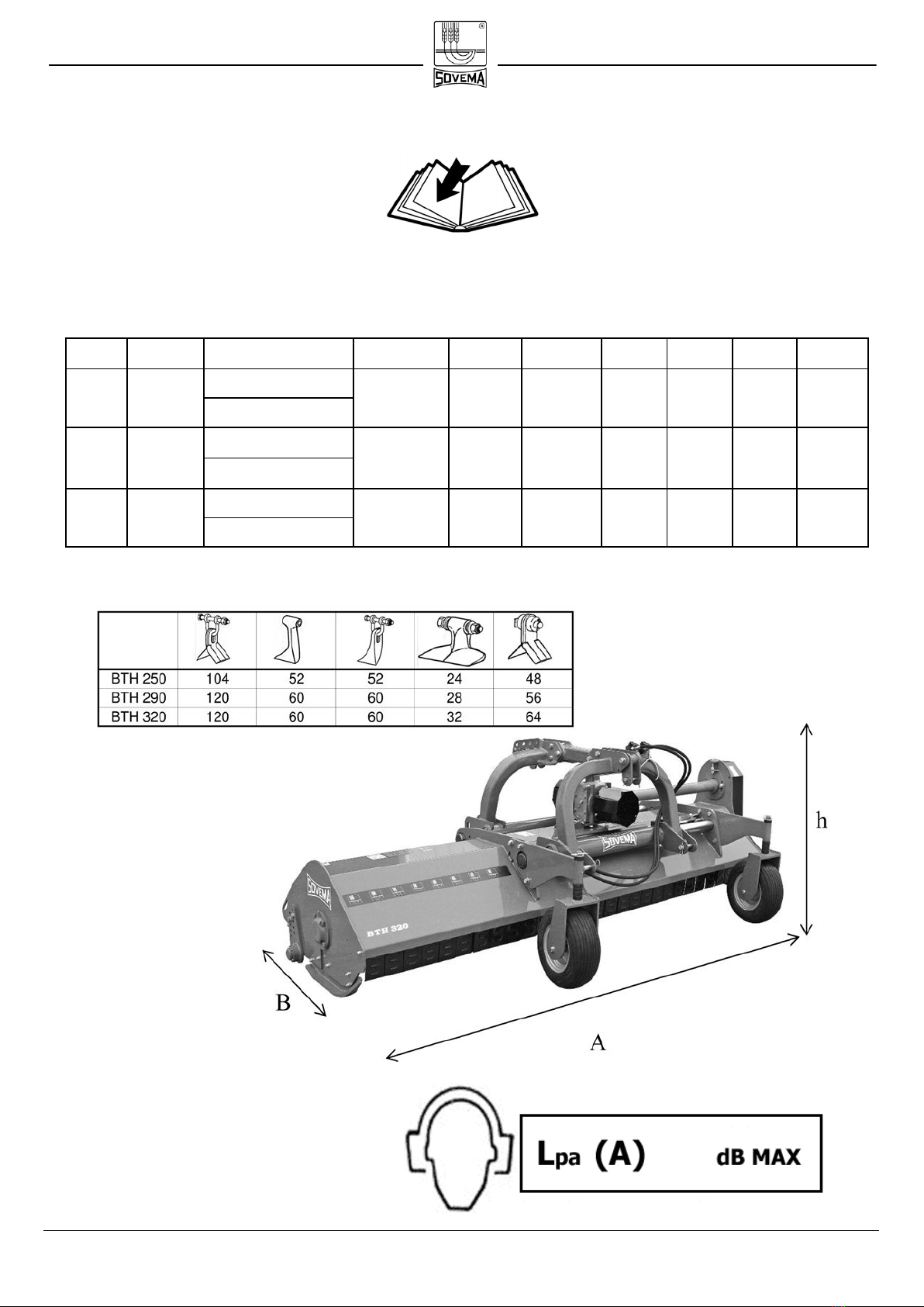
TECHNICAL SPECIFICATIONS
The implement described in this manual is a flail mower from the BTH series.
NOISE LEVEL WHEN IDLE.
80
PTO Rotor
c m in ch
rig ht side left side R PM R PM c m inch cm i nch c m inc h Kg Lbs
c m 128 cm 128
inc h 50 inch 50
cm 71 cm 185
inc h 28 inch 72
c m 145 cm 153
inc h 57 inch 60
cm 88 cm 210
inc h 35 inch 82
c m 156 cm 162
inc h 61 inch 64
cm 99 cm 219
inc h 39 inch 86
40 960 2112
11 4 40 920
11 4 45 102
10245320 126 2024117BTH 290
134BTH 320
59-81
66-81
540 / 1000
340
278 109 11 4 45 102 40 880 1936
W eighthBA
1845 / 1950
1845 / 1950
1845 / 1950125 90-110
70-110
80-110
100 51-81 540 / 1000
MO DEL HP
540 / 1000318
W ork w idth Side s hift (from cent re) KW
BTH 250 256
298

INSTRUCTION MANUAL Pag. 12 Revision 2013
HITCHING THE MACHINE
The machines described in this manual do apply to any kind of tractor provided of
universal three-point hitch.
The characteristics (length, diameter of the holes for the lifting pins) of the tractor's lifting
arms depend on the type of tractor, therefore it is necessary to prepare the machine in
order to properly hitch the machine.
Before attaching the machine to the tractor you must make sure that the engine is turned
off, brakes are locked and the ignition key is removed.
This operation must be performed on a flat area as it is very dangerous.
Do not allow anyone between tractor and implement
when the engine is running.
Follow these instructions:
• Connect the two drawbar of the tractor to the lower plates of the mower by using
two pins and two hair pins to lock the pins in place (fig. 1).
UPPER
PLATES
LOWER
PLATES
Fig.1

INSTRUCTION MANUAL Pag. 13 Revision 2013
• Connect the 3rd point of the tractor to the high plates of the mower by using a pin
and an hair pin (fig. 1).
• Lift the mower and fix the stand support high in its socket with the supplied pin.
• Lower the mower and adjust it so that it is parallel to the ground. Do this by
adjusting the 3rd point drawbar (fig. 2). This will improve the life-span of the
machine and the PTO.
• Connect the PTO shaft and make sure it is correctly connected to the tractor and
the machine.
NOTE ON THE PTO SHAFT.
Always refer to the manufacturer’s instruction manual. Read it carefully.
Fig.2
NO!
YES!
INSTRUCTION MANUAL Pag. 14 Revision 2013
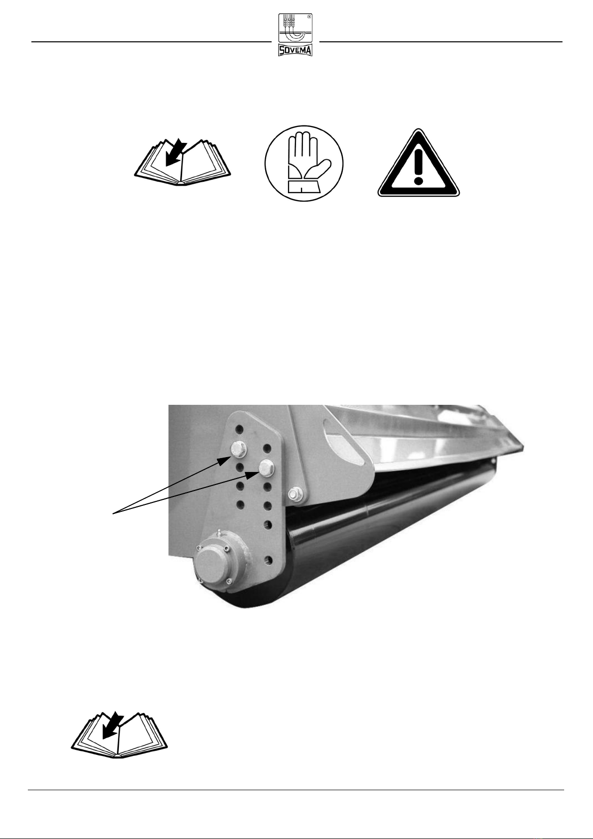
CUTTING HEIGHT REGULATION
Rear roller adjustment
Rear roller adjustment is carried out by regulating the two roller support plates as follows
(fig. 1):
• Unscrew and remove screws “a” from the roller’s plates
• Adjust the wheel as preferred.
• Place screws “a” back.
Fig.1
In order to get an even cut, it is suggested to adjust the
two plates at the same height.
a
INSTRUCTION MANUAL Pag. 15 Revision 2013
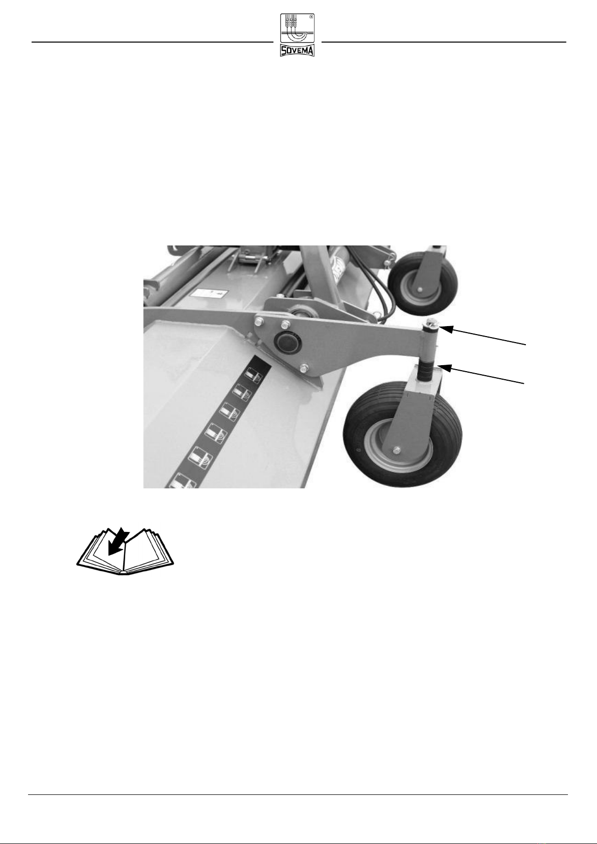
Wheel-equipped machines
If your mower is equipped with two front wheels, the cutting height adjustment is carried
out by adjusting the spacers of each wheel. (fig. 2)
• remove the split pin.
• Adjust the skid as needed.
• Insert again the split pin.
For each wheel, please adjust the two support at the
same height.
INSTRUCTION MANUAL Page 16 Revised 2013
OPERATING THE IMPLEMENT
After having completed all safety checks and made sure the mower is parallel to the
ground, proceed as follows::
• Raise the machine off the ground in order to let the knives start moving without
touching ground to avoid damages.
• Maintaining the machine raised, engage the tractor PTO at suggested engine RPM.
• Start moving the tractor forward and then gradually lower the machine
CUTTING TIPS.
Proper ground speed for cutting will depend upon the
height, type and density of the grass to be cut. However
we suggest not to exceed 7 Kph (4.3 Mph).
Lower ground speed allows tall and dense grass cutting. Taking a partial cut and/or
reversing the direction of travel may also produce a cleaner cut. Remember, sharp knives
produce cleaner cuts and require less power.
Important: Very low cutting heights should be avoided.
Damaging shock loads occur when the knives strike the
ground repeatedly. This can cause damage to the ma-
chine.
During operation, always raise the machine off the
ground before doing a curve to avoid damage to the roller
supports and to the lateral sides where the skids are po-
sitioned.

INSTRUCTION MANUAL Page 17 Revised 2013
The machine must be used only if equipped with all its
components as supplied by the Manufacturer (safety
devices included). The implement must not operate
without the rear shield or modified as to leave the rear
shield open. No other component can be modified.

INSTRUCTION MANUAL Page 18 Revised 2013
TROUBLESHOOTING
During work several problems can happen.
UNUSUAL NOISES.
During operations, if the implement produces loud, unusual noises, the operator must
immediately stop it and follow these instructions::
• Make sure there are no broken mechanical parts.
• Verify that the gearbox contains the correct amount of oil.
If the oil level is too low (please see the chapter on maintenance), the gears of the conic
couple are not adequately lubricated and will overheat the remaining oil if operations
continue. This will rapidly produce damages to the conic couple and its bearings.
• Check knives conditions.
If some of the knives are broken, bent or present excessive wear, the balance of the rotor
will be compromised. During operations, the turning movement of the rotor will produce
vibrations that will inevitably damage and break support bearings and frame welds. To
avoid damages, please replace all the knives at the same time with new, original knives
supplied by the manufacturer.
• Check rotor support bearings.
As a consequence of reduced lubrication, one of the bearings supporting the rotor may
have broken down. The rotor starts to oscillate producing excessive vibrations against
the frame, producing damages to the welded parts of the frame.
Another cause for damaged support bearings can be the impact with heavy, fixed objects
on the ground such as rocks.

INSTRUCTION MANUAL Page 19 Revised 2013
CUTTING ANOMALIES.
If after the operations the mower failed to obtain a clean, even cut, the operator must
follow these instructions:
• Check knives conditions.
The knives can be worn and less effective. Please replace them.
• Check if the cutting height has been properly set up.
The regulation of the implement may be uneven. Please check that both skids are at the
same height.
• Check belt conditions after removing the cover.
It is possible that the belts are not tight enough, thus failing to transmit enough power to
the knives. The sliding can be produced by lack of tightness or by belt wear.
- If the belts look even marginally damaged, the operator must replace them
immediately
- If the belts are loose, the operator must tighten them
A less-than-adequate result can be produced by an incorrect working speed. The
advancement speed must be regulated in connection to the engine’s RPM and
consequently to the rotor’s RPM. Advancing too quickly doesn’t allow the knives to cut
thoroughly.
Before checking the machine to find the possible cause
of malfunctioning, make sure the tractor's PTO is discon-
nected, the engine is turned off, brakes are engaged, the
ignition key is off the command board and the machine is
completely lowered to the ground..

INSTRUCTION MANUAL Pag. 20 Revised 2013
DISCONNECTING THE MACHINE
The disconnection of the machine from the tractor must be carried out on a flat surface. It
a dangerous operation. Please read the following instruction carefully.
• While remaining in the tractor seat, put the tractor PTO in neutral.
• When the rotor has completely stopped, turn off the engine and set the parking
brakes.
• Descend from the tractor, remove the pin from the top plates of the mower after
removing the safety key from the pin. Then proceed to remove the third point.
• Remove the pin from the lower plates of the mower after removing the safety key
from the pin. Then disconnect the lifting arms from the machine.
• Remove the PTO Shaft.
Always check the tractor’s PTO is in neutral before dis-
connecting the PTO shaft!
This manual suits for next models
2
Table of contents
Other Sovema Farm Equipment manuals


Popular Farm Equipment manuals by other brands

Schaffert
Schaffert Rebounder Mounting instructions

Stocks AG
Stocks AG Fan Jet Pro Plus 65 Original Operating Manual and parts list

Cumberland
Cumberland Integra Feed-Link Installation and operation manual

BROWN
BROWN BDHP-1250 Owner's/operator's manual

Molon
Molon BCS operating instructions

Vaderstad
Vaderstad Rapid Series instructions


