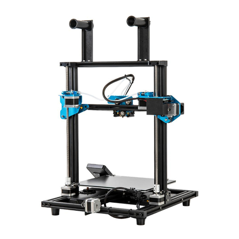
Sovol SV01 Manual

SV01
Guide Book
To make Top-quality 3d printer
V.2.0En

Select the correct input voltage to mach your local mains (220V or 110V).
Not use the printer any way other than described here in order to avoid personal injury or property damage.
Do not place the printer near any heat source or ammable or explosive objects. We suggest placing it in a well-ventilated,
low-dust enviroment.
Do not expose the printer to violent vibration or any unstable enviroment, as this may cause poor print quality.
Before using experimental or exotic laments, we suggest using standard laments such as ABS or PLA to calibrate and test
the machine.
Do not use other power cable except the one supplied. Always use a grounded three-prong power outlet.
Do not touch the nozzle or printing surface durint operation as they may be hot. Keep hands away from machine while in
use to avoid burns or personal injury.
Do not wear gloves or loose clothing when operate the printer. Such cloths may become tangled in the printer moving parts
leading to burns. Possible bodily injury, or printer damage.
When cleaning debris from the printer hotend, always use the provided tools. Do not touch the nozzle directly when heated.
This can cause personal injury.
Clean the printer frequently. Always turn the power off when cleaning, and wipe with a dry cloth to remove dust, adhered
printing plastics or any othe material off the frame, guide rails, or wheels. Use glass cleaner or isopropyl alcohol to clean the
print surface before every print for consistent results.
Children under 10 years of age should not use the printer without supervision.
1
2
3
4
5
6
7
8
9
10
11
Notes

Preface
This Guide is designed for Sovol users to start their
printing journey.
We still recommend that please read this guide even if
you are familiar with the 3d Printing technology, as
there are lots of important information about the sovol
for you get a better 3d experience.
In this guide there are links to video tutorials and
downloads, use the Qr-codes or Click to access.
Additional resources and information:
(1) Quick start Guide
Quick start user guide or video found on the Micro Sd
card.
(2) Ofcial website: www.sovol3d.com
Find out all the latest news which contains the
up-to-date information concerning software, rmware,
device maintenance and so on.
3) Sovol Ofcial User Group on Facebook.
Be a part of the Sovol community sharing your projects
and helping each other.
Index
Index
02 Printer Parts
03 Box Contens
04 Assembly
08 Cable Connection
09 Quality Adjustments
10 Screen Information
11 Bed Leveling
12 Loading Filament
13 Software Installation
14 Preparing to Print
15 Conection Diagram
16 BLTouch Installation
17 After-Sales Service
01

02
1
2
3
4
5 6
7
8
9
10
11
12
13
14
15
16
Printer Parts
1. X Axis Motor
2. Main control box
3. Hot bed
4. TF Card and Usb
5. Display screen
6. Button knob
7. Nozzle kit
8. Extrusion kit
9. Filament holder
10. Filament sensor
11 Couplers
12. Y Axis Motor
13. Foot pad
14. Z Axis Motors
15. Power switch
16. Leveling nut

1
2
3
4
5
6
7
8
9
10
11
12 13 14
Box Contens
03
1. Gantry
2. Base with hot bed
3. Filament holder
4. Display Screen
5. Usb cable
6. Z Axis switch limit plate
7. Screws, T-Nuts and extra nozzle
8. Micro SD card and Reader
9. Power cable
10. Filament (200gr.)
11 Pliers
12. Spatula
13. Tool set
14. Nozzle cleaner (0.4mm)

Assembly Steps 1-2
4
M5x25 + WASHERS (4 Units)
Front
A
1
Remove the parts from the box.
Note that the base and gantry are
connected at the factory. If possible,
perform this operation with the help
of another. Remove any tape and
padding from the parts. Inspect the
parts to make sure they were not
damaged in shipment.
Install the gantry (A) to the base (B).
a) On the gantry frame make sure
the nozzle assembly is in to the
front, and the long vertical leads
screws is in to the back.
b) On the base frame, make sure
the black belt tensioner is on the
front, and the stepper motor is on
the back.
Use the M5x25 screws (4) with their
washers. Lift the base frame. Install
the screws through the base frame
into the threaded holes in the gantry
frame. Tighten with an Hex key
(Allen). Do not exceed tightening to
avoid deformations in the frame.
1
2
2
B
04
Front
4mm

33Install the lament spool holder.
Secured in the screw hole of the
lament holder with M4x8 (2)
and M4 T-Nut (2). Loosen the
T-nuts by hand and turn them so
they will t inside the grooves on
the frames.
You want the nuts to be loose so
that when you tighten the bolts,
the nut will rotate 90° and grab
onto the inside of the groove.
Tighten with an Hex key (Allen).
Assembly - Step 3
05
M4x8 + T-NUTS (2 Units)
2.4mm

4
5
4Install the lament sensor.
The plate with the lament sensor is
installed in the upper rear part of the
frame. The correct direction is indicated by
an arrow on the sensor housing. Fixing to
the frame is similar to the method used
previously. Use the M4x8 (2) screws with
M4 T-Nut (2). Loosen the T-nuts by hand,
when you tighten the screws, the nut will
rotate 90° and grab onto the inside of the
groove.
Install the Lcd screen.
The screen is mounted on the right front of
the base frame. Use the M5x20 (2) screws
provided with their washers. Install the
screws throught the Screen plate into the
threaded holes in the bottom frame.
In another step, we will explain how to
make screen connections
5
06
M5x20 + WASHERS
(2 Units)
M4x8 + T-NUTS (2 Units)
Assembly - Steps 4-5
2.4mm
4mm

07
Assembly - Step 6
6
6Install the Z limit switch
This device sets the starting height of the
Z axis, which is responsible for the up and
down movement of the print head.
It is placed next to the left Z stepper motor
and xed to the edge of the vertical frame
using the included T-nuts.
Loosen the T-nuts, place a card or slightly
thick paper in the bottom frame and rest
the sensor plate on the top. This will
provide the correct minimum height,
slightly above the horizontal prole. Tighten
the screws and connect the 2-wire
connector labeled "Z".
M4x10 + T-NUTS (2 Units)
3mm

X
EXP1
EXP2
Z
E
4-WIRE CONNECTORS
X Y Z
2-WIRE CONNECTORS
ZZ EYX
FD
Y
Z
ZY
X
Make connections
The cables are provided with
labels, observe them and the type
of connector for proper
identication.
Make the connections being
careful not to bend the connector
pins.
The display board has three
identied inputs. Connect the
Exp1 and Exp2 cables in their
corresponding place leaving the
Exp3 input empty..
Cable Connection
08
IMPORTANT
Do not forget to place the voltage selector in the position
corresponding to your local mains (220V or 110V).
Use a grounded electrical outlet.

Quality Adjustments
09
Sovol printers are pre-assembled at the
factory, however, to obtain the best print
quality, some adjustments must be made.
Eccentric nut adjustments.
In each movement group there are some
wheels provided with eccentric nuts.
You must adjust them to get enough
rmness and smooth movement at the
same time. Properly adjusted, you should
be able to turn the wheels with your
ngers with a little force.
The adjustment of the wheels that guide
the Z axis also helps to have a
synchronized movement of both sides of
the horizontal prole and the correct
leveling of them.
Belt adjustments.
The X and Y axis are moved by belts.
At the end of each axis there is a
tensioner that can be adjusted. Check
regularly that the belts have enough
tension.
3mm

1 3
542
6
7
10
11
8
9
1. SET TEMPERATURE NOZZLE
3. SET TEMPERATURE HOT BED
5. LAYER FAN SPEED (%)
7. PRINT SPEED (%)
9. PRINT PROGRESS
11. BUTTON KNOB
> PRESS: Conrm/Enter Sub Menu ROTATE: Move/Change value
2. CURRENT TEMP. NOZZLE
4. CURRENT TEMP. HOT BED
6. CURRENT LOCATION NOZZLE
8. PRINT TIME
10. PROMPT MESSAGE
Screen Information
10
Prepare
Control
No Card/
Print TF
Disable
Steppers
Move Axis
Auto Home
Not Printing (Sovol ready)
Menu Sub Menu
Moving X, Y, Z axis
or Extruder by imputing
Close motors and move X, Y, Z
axis by hands
Return to Zero
Explanation
Temperature
Heats hotend and bed, fan speed
or set the preset Pla/Abs preheat
entering a value
Store
Settings
Save the modied
conguration in memory
Initialize
EEPROM Restore factory settings
No card in the printer /
Print from TF card
Cooldown Turn off the heaters
Preheat Pla
Preheat Abs
Preheat hotend, bed or both
at the preset temperature
Tune
Pause
Stop
Speed
Nozzle
Bed
Fan Speed
Flow
PRINTING
Menu Sub Menu
It allows to modify:
print speed, fan speed,
nozzle temperature,
bed temp. and lament ow
while printing
Explanation
Pause printing, resume
Stop printing

Bed Leveling
11
1.Prepare > Auto Home
2.Prepare > Disable Steppers
3.Prepare > Preheat PLA > Preheat PLA Bed
Run the sequence to level
1. Auto Home - The nozzle will move to the
zero point on the XYZ axes.
2. Disable Steppers - The motors are
released to allow manual movement.
3. Preheat Pla Bed - Optional, but
recommended to recreate the printing
temperature conditions.
Slide a paper between the bed and nozzle
If necessary, adjust the bed so that the
paper can be placed in the rst corner.
Level the four corners of the bed
Adjust each of the four thumbscrews under
the bed until the piece of paper slides, with
just a tiny bit of drag, in all locations on the
build plate.
When nished, cool the bed, if heated, using
the menu Prepare>Cooldown
Tip: The Z axis motors are also disabled. So
you should handle the print head gently
keeping it at during the leveling process. If
you put too much pressure, you will lose the
initial Z position obtained with Auto Home
getting an invalid leveling.
TOO FAR
The lament can not
adhere to the platform.
CORRECT DISTANCE
Filament are extruded evenly
just sticking on the platform
TOO CLOSE
Filament are not extruded
enough, even scraping the platform
2
4 3
1
1
2
3

Loading Filament
12
Prepare > Preheat PLA > Preheat PLA End
-
Prepare > Preheat ABS > Preheat ABS End
METHOD 1
Control > Temperature
> Nozzle > 200°
METHOD 2
Printing: Cut the lament in use near the extruder, feed slowly with the new lament
until the extruder takes it.
Not printing: Preheat the nozzle at least to the melting temperature of the lament
that is installed. Pull the lament to remove it, insert the new lament and feed until
it comes out of the nozzle.
TIP: HOW TO REPLACE THE FILAMENT ?
Heat the nozzle
Method 1: Use the printer's Preheat
presets to heat Pla or Abs temperature
according to the temperature range of
the lament you are going to use.
Method 2: Set the temperature
manually in the printer menu Control
Pass the lament through the sensor
Insert the lament into the extruder
When the nozzle is hot, press and hold
the extruder lever, and insert the
lament through the small hole of the
extruder until it comes out of the
nozzle.
When nished, cool the nozzle, using
the menu Prepare>Cooldown
1
2
3

Software Installation
13
Cura.exe
Install Cura
There is a Cura installer on
the MicroSd card included
with the printer.
To download the latest
version visit the website of
Ultimaker
Open Cura and add a New
Printer
Choose Creality Cr-10 as
the base prole and change
the name to Sovol Sv01.
Adjust the size
Enter 280mm, 240mm and
300mm as the printer size
for X, Y and Z.
Congure retraction
The main difference
between Sovol Sv01 and
Cr-10 is the Direct Drive
Extruder. Retraction
distance values of ~ 3mm
and ~ 50mm/s as
retraction speed are
suitable.
1
2
3
4

Load a model in Cura
On the SD card you will nd a
calibration cube so you can
perform an initial test.
Choose settings
Cura has a menu with basic
print settings. If you want
advanced settings, click
Custom.
Make the Slice
Cura will perform the
necessary calculations and
generate a gcode le with the
paths and parameters for the
printer.
Save the gcode le to the card
Use the USB reader provided
with the printer.
Print the model
Insert the SD card upside
down in the printer, select the
gcode le in the menu and
print.
1
2
3
5
4
Install Cura
There is a Cura installer on
the MicroSd card included
with the printer.
To download the latest
version visit the website of
Ultimaker
Open Cura and add a New
Printer
Choose Creality Cr-10 as
the base prole and change
the name to Sovol Sv01.
Adjust the size
Enter 280mm, 240mm and
300mm as the printer size
for X, Y and Z.
Congure retraction
The main difference
between Sovol Sv01 and
Cr-10 is the Direct Drive
Extruder. Retraction
distance values of ~ 3mm
and ~ 50mm/s as
retraction speed are
suitable.
Preparing to Print
14
xyz-cube.stl
> Print from TF > xyz-cube.gcode

BLTouch Installation
16
BLTouch is an optional device for
automatic leveling. Installation
requires the disassembly of the
printer base and the rmware
update.
BLTouch device assembly
Watch the linked videos for a
detailed guide.
Download Firmware
On our website you will nd an
updated Firmware for BLTouch,
pay attention to download the
correct version.
sovol3d.com/pages/download
Update the Firmware from Cura
Open Cura, connect the printer to
your computer using the Usb
cable and load the Firmware from
Printer Preferences into the Cura
software. Wait without
disconnecting until the process is
nished.
In our video tutorials you will nd
an alternative method.
1
2
3
DON’T YOU HAVE A BLTOUCH?
Go to sovol3d.com and get yours.
SOVOL VIDEO
youtu.be/s_Bh4_cOWXY
SOVOL VIDEO
youtu.be/BTCXNLIzrz8

After-Sales Service
17
Service
1.The printer can be returned within seven days, 15 days replacement, one-year warranty, lifetime maintenance.
Every machine is assembled and tested by our expert staff before departing our facilities.
Replacement requirement
1. The appearance of the product is intact, without damage, cracks, deformation, etc.;
2. Machine is complete including all parts, tools, original box, and foam padding;
3. Provide a valid purchase invoice, product numbers should be the same.
Warranty coverage
1. The following accessories are not included in the warranty coverage ( unless damaged by transportation): platform sticker;
platform forming plate; acrylic cover; card reader and TF card; platform glass; USB cable; lament; rack and tools, etc.
2. Prole: Small blemishes in the black paint due to testing or shipping are not covered in the premise that the blemish does not
affect normal use;
3. Nozzle assembly (nozzle, heating block, throat pipe , heat sink, Teon tube, etc.) warranty period is 3 months. If damage occurs
after the warranty expires, you will be responsible for replacement;
4. 12 Month Warranty on the motherboard, LCD display, power supply, heated bed. The free warranty maintenance is provided by
the original factory over the warranty period. After Warranty expires, original factory maintenance is available, but the customer is
responsible for shipping and maintenance costs;
Not included in warranty coverage:
1. It will be difcult to provide an effective warranty service if you can not provide a correct serial number;
2. The whole machine and components exceed the warranty period;
3. Equipment failure or damage caused by unauthorized modication of the equipment (private modication includes:
a) modication of the nozzle assembly; b) modication of the machine structure; c) use of third-party components;
d) use of third-party rmware procedures or change the original Factory rmware program, etc.);
4. Equipment failure or damage due to incorrect installation and use;
5. Equipment failure or damage caused by use in a non recommended working environment specied by this manual
(Unstable, dusty, moisture);
6. Equipment failure or damage due to improper use (beyond workload, etc.) or maintenance;
7. Equipment failure or damage due to the use of other branded components or other inferior consumables.
Table of contents
Other Sovol 3D Printer manuals
Popular 3D Printer manuals by other brands
Hello Bee Prusa
Hello Bee Prusa DIY 3D PRINTER KIT user manual
ALVEO3D
ALVEO3D PrinterCase instruction manual

Mingda
Mingda Magician X Instructions for assembly
TUKKARI
TUKKARI TS Acrylic Assembly instructions
Blackbelt 3D BV
Blackbelt 3D BV BLACKBELT 3D Printer Installation & user manual
Stef's Engineering
Stef's Engineering Prusa I3 MK3 Build instructions


