Spa Electrics Atom Operating instructions

VINYL POOLS
ULTRA COMPACT NICHE LIGHT
INSTALLATION &
OWNER’S MANUAL

6
7
13
14
FINISHED INSTALLATION
INSTALLATION PROCEDURE
LIGHT ASSEMBLY
LIGHT REMOVAL
READ THIS FIRST 3
4
4
5
16
TOOLS REQUIRED
PRODUCT SUPPORT AND INFORMATION
INCLUDED PARTS
TROUBLESHOOTING
18
KEY DIMENSIONS
MULTI-COLOUR OPERATION
CABLE ADJUSTMENT & REMOVAL
NOTICE
21
20
FRESH WATER USE ONLY
HORIZONTAL MOUNT ONLY
NOT INTENDED FOR OPERATION OUT OF WATER
2
CONTENTS

Congratulations on your purchase of the ATOM underwater lighting system. All ATOM lights are
manufactured by Spa Electrics in Australia from only the highest quality materials. For more
information about Spa Electrics & our products, please visit www.spaelectrics.com.au
BEFORE YOU START:
• ATOM cables can be shortened to suit individual installation requirements. Spa Electrics
recommends all cabling is protected by conduit and that a junction box (or similar) is
incorporated into pool cabling design to avoid siphoning.
• Ensure that the lighting system is installed by a qualified person (e.g. registered pool builder
and/or licensed electrician), in accordance with the most current edition and/or amendment of
current AS/NZS 3000 Wiring Rules.
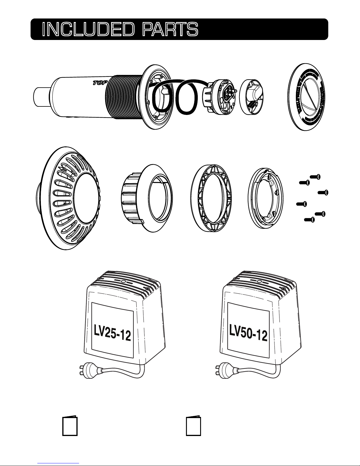
• For safe and proper installation, ensure that only those parts supplied with the system are used.
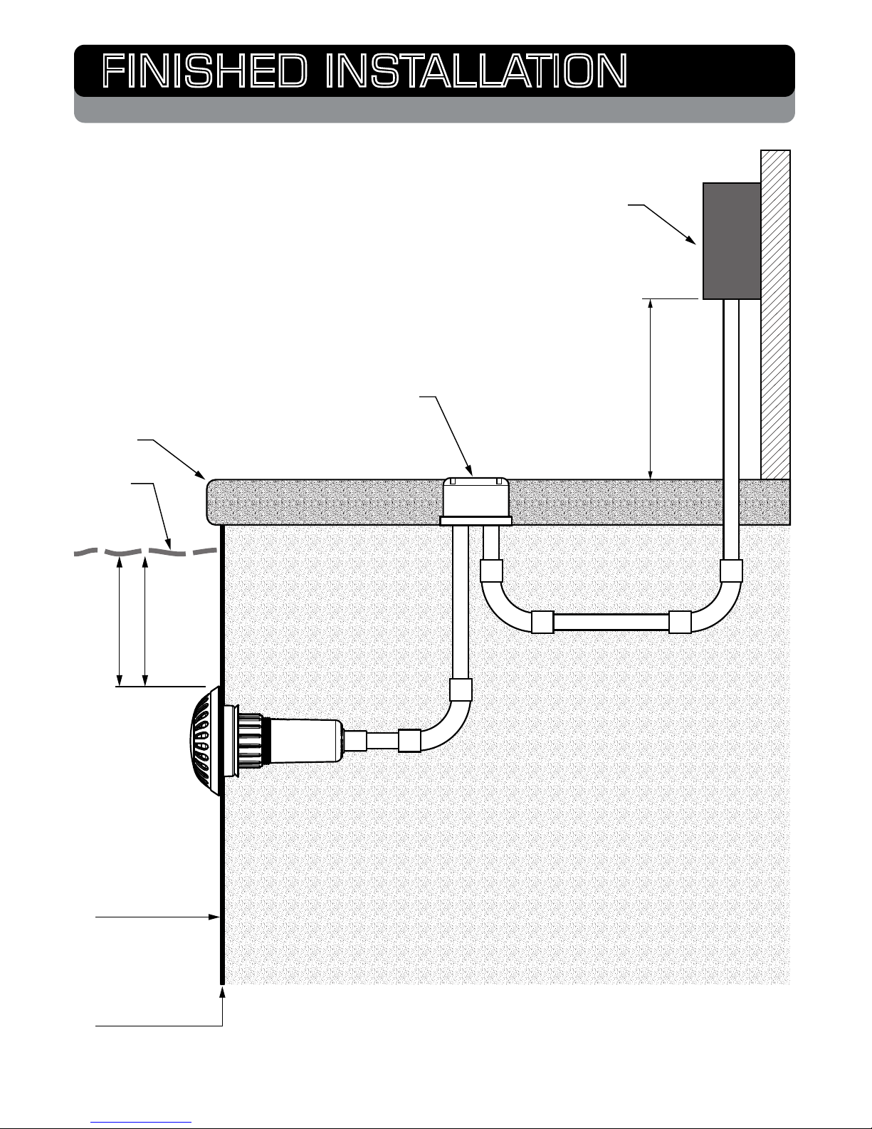
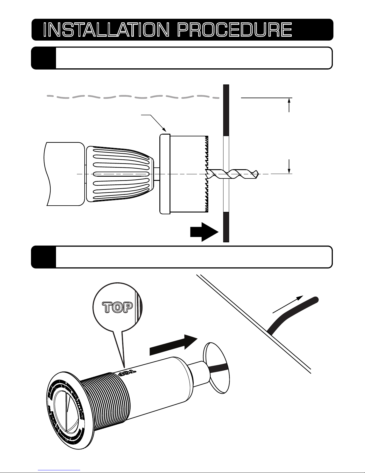
• Maximum installation depth for the ATOM light is 400mm (16”) below water line (to top of light).
• All lights should be mounted in a location that is easily accessible without the need for entering
or lowering the pool water.
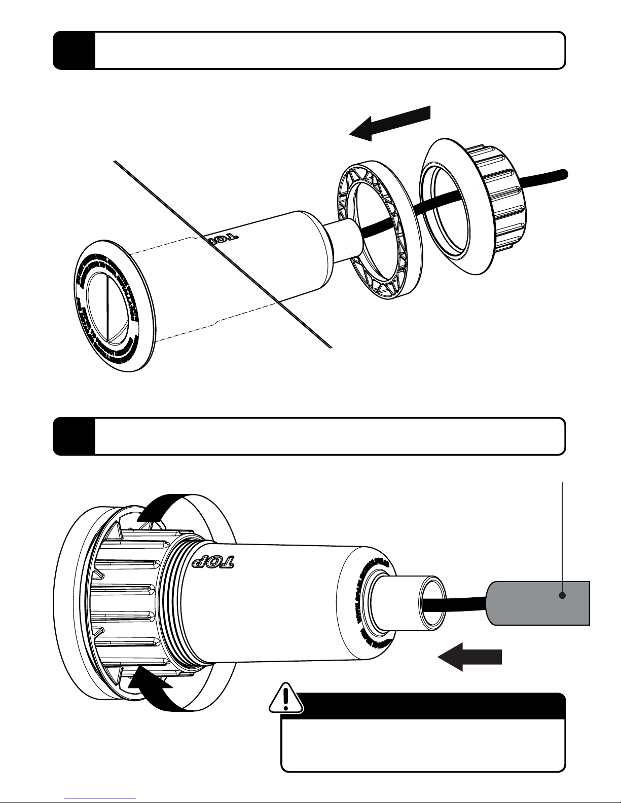
• 700mm (28”) cable has been supplied pre-assembled within niche assembly, and must remain
stored within the Niche to ensure the light can be accessed above the waterline. [Maximum cable
within niche = 1000mm (40”) (up to 1.0mm2). See Page 16 for more information].
CLEANING
• Only use warm water and a soft brush or cloth to clean ATOM lights. DO NOT use detergents or
spirits as this can damage the light and void your warranty.
USE
• DO NOT operate light unless completely submerged in water.
• Operating the light for at least 15 minutes every week is advised (all year round).
• ATOM lights are suited for both domestic and commercial installations and can be operated
continuously (24/7) if required.
• Temperature range for installation, operation and servicing: +5oC ~ +40oC (+41oF ~ +104oF)
It is recommended that the ATOM lighting range is operated using a Spa Electrics LV25-12 or
LV50-12 transformer.
• DO NOT use electronic or switch-mode power supplies with ATOM lights. These power supplies will
damage the light and void your product warranty.
• Pool chemicals & PH levels: Due to the corrosive nature of unbalanced pool chemicals, Spa
Electrics strongly recommend that your pool water is balanced prior to installing your pool lights or
any plastic or stainless steel components, and tested weekly to maintain these levels. pH levels
should be maintained between 7.2 – 7.6 at all times to ensure the longevity of these components.
> Failure to do so can result in chemical damage to the light housing and pool fittings,
including stainless steel components.
> Please note: Lights or components found to have excessive chemical damage will not
be covered under our manufacturer’s warranty policy.
• This light contains no user-serviceable parts; opening the light will void the product warranty.
IMPORTANT NOTE
3
READ THIS FIRST

PRODUCT SUPPORT & INFORMATION
•Hole Saw - Ø65mm ~ Ø70mm (2 5/8” ~ 2 3/4”saw)
•Box cutter / knife
•No. 2 Phillips screwdriver
•Flat-blade screw driver (for light-head removal)
IMPORTANT NOTES
• The use of power tools for product assembly is NOT recommended as these
devices can cause faults and damage to light components.
• The enclosed images are for illustrative purposes only. Appearances of parts
and assemblies may vary from the enclosed illustrations.
• Please contact your reseller if you have any questions regarding the correct
installation of this product.
Phone: +61 (0)3 9793 2299 (business hours)
Email: info@spaelectrics.com.au (SALES enquiries)
Email: tech@spaelectrics.com.au (TECHNICAL support enquiries)
Web: www.spaelectrics.com.au
4
TOOLS REQUIRED

CONICAL
NUT
CONICAL
WASHER
6x SCREWSCLAMP
RING
1x WARRANTY CARD 1x INSTALLATION MANUAL
LIGHT
NICHE CAP
NICHE ASSEMBLY PLUG + CABLE
1x LV25-12 TRANSFORMER
(FOR SINGLE-LIGHT KITS)
1x LV50-12 DUAL TRANSFORMER
(FOR DUAL-LIGHT KITS)
5
INCLUDED PARTS

VINYL LINER
STEEL WALL
All light conduits must be run in individual
lengths back to transformer location. An air-loop
or junction box must be installed as part of each
conduit run to prevent pool siphoning.
NOTE: Conduit should contain a draw-wire to
allow easy installation of power cable.
300mm (MIN)
CONDUIT ABOVE
WATER / GROUND
POWER SUPPLY
(TRANSFORMER)
400mm (MAX)
WATER
LINE
COPING
50mm (MIN)
RECOMMENDED
INSTALL DEPTH
AIR-LOOP OR
JUNCTION BOX
6
FINISHED INSTALLATION
STANDARD WALL MOUNTING

* MAY NOT BE REQUIRED IF PRE-PUNCHED / DRILLED HOLES AVAILABLE FOR LIGHT MOUNTING
Ø65~Ø70mm
(2 5/8”~ 2 3/4”)
HOLESAW
DRILL HOLE THROUGH STEEL WALL
ESTIMATED WATERLINE
470mm (MAX)
120mm (MIN)
BELOW ESTIMATED
WATERLINE
FEED CABLE
THROUGH
HOLE
7
INSTALLATION PROCEDURE
2
ORIENTATION OF NICHE “TOP”
1
MOUNTING HOLE PREPARATION *

FIRMLY TIGHTEN
BY HAND ONLY
* GLUING NOTE
ENSURE P.V.C. SOLVENT CEMENT IS SUITABLE
FOR NON-PRESSURE APPLICATIONS AND USE
WITH A.B.S. PLASTIC
20mm OR 25mm BELL
MOUTH CONDUIT GLUED
TO CONDUIT TAKE-OFF
(SEE *GLUING NOTE BELOW)
8
3
ASSEMBLE WASHER AND NUT
4
TIGHTEN NUT

VINYL LINER
INSTALLED OVER
STEEL WALL
FIRMLY TIGHTEN
FASTENERS BY HAND ONLY
IN NUMBERED ORDER *
THIS FASTENER
LOCATED AT TOP
1
23
46
5
* RECOMMENDED
FASTENING ORDER
9
5
REMOVE NICHE CAP
6
ASSEMBLE VINYL CLAMP RING

CLAMP
RING
CUT & REMOVE
VINYL INSIDE
CLAMP RING
REMOVE
PROTECTIVE
CAP
10
7
TRIM VINYL
8
REMOVE PROTECTIVE CAP

NOTE
ENSURE SEAL IS
SEATED FLAT IN
PLUG BASE
NOTE
DO NOT REMOVE
TERMINAL COVER
UNDERWATER
SERVICING
RETAIN TERMINAL COVER IN
CASE LIGHT NEEDS REMOVAL.
SEE PAGE 15 FOR MORE INFO
REMOVE TERMINAL
COVER FROM PLUG
USING PHILLIPS-HEAD
(NO.2) SCREW-DRIVER
TERMINAL
COVER
11
9
REMOVE TERMINAL COVER

• DO NOT OVERTIGHTEN SCREWS
• DO NOT USE POWER-TOOLS
• DO NOT ADD SEALANTS, GREASES OR ADHESIVES
• ENSURE ALL SURFACES ARE CLEAN AND DRY
• DO NOT ASSEMBLE UNDERWATER
IMPORTANT NOTES
FASTEN PLUG TO LIGHT USING
3 x (M3.5 x 25mm) FASTENERS
& NO.2 PHILLIPS-HEAD
SCREWDRIVER
ALIGN TERMINAL PINS
AND FIRMLY ASSEMBLE
PLUG TO LIGHT
12
10
FASTEN PLUG TO LIGHT

1
1
2
ROTATE 15 DEGREES
COUNTER-CLOCKWISE
FROM ‘TOP’ TO ALIGN
WITH LOCKING
MECHANISM
ROTATE CLOCKWISE
TO LOCK LIGHT IN
PLACE
2
“CLICK”
13
LIGHT ASSEMBLY
1COIL CABLE INSIDE NICHE
INSERT LIGHT INTO CLAMP RING
2

ROTATE & RELEASE
LIGHT FROM NICHE
1
2
HOLD DOWN
BUTTON WITH
FLAT-BLADE
14
LIGHT REMOVAL
1
PUSH & HOLD BUTTON WITH FLAT BLADE
2
ROTATE COUNTER-CLOCKWISE & REMOVE FROM LOCKING RING

2
UNSCREW 3x FASTENERS
USING NO.2 PHILLIPS-HEAD
SCREWDRIVER
1
ASSEMBLE TERMINAL COVER TO PLUG
USING NO.2 PHILLIPS-HEAD SCREW-
DRIVER
PLUG CAN BE STORED WITHIN
NICHE AS PICTURED
1
2
15
PLUG REMOVAL
PLUG REMOVAL & TERMINAL COVER ATTACHMENT
1
REMOVE PLUG FROM LIGHT
2
ASSEMBLE TERMINAL COVER TO PLUG & STORE IN NICHE

A
CABLE ADJUSTMENT
B
CABLE REMOVAL
CABLE GROMMET
COMPRESSION PLATE
FASTENERS
700mm
(STANDARD)
A B
1000mm (MAX)
AFTER CABLE
ADJUSTMENT
CABLE GLAND
1
2
USING A NO. 2 PHILLIPS-HEAD
SCREW-DRIVER, PARTIALLY LOOSEN
FASTENERS 1 & 2 TO ALLOW CABLE TO
SLIP THROUGH NICHE.
DO NOT EXTEND CABLE LONGER THAN
1000mm (SEE ABOVE) - EXCESS CABLE
WITHIN NICHE WILL RESTRICT
CORRECT ASSEMBLY OF LIGHT HEAD.
USING A NO. 2 PHILLIPS-HEAD
SCREW-DRIVER, COMPLETELY REMOVE
CABLE GLAND COMPONENTS AND
STORE SAFELY FOR LATER-USE.
ENSURE CABLE-GLAND COMPONENTS
ARE RE-ASSEMBLED TO CABLE IN THE
ORIENTATION & ORDER SHOWN ABOVE
PRIOR TO FASTENING BACK INTO
NICHE.
ATOM lights (for vinyl pools) are supplied with 700mm of cable pre-installed within the
niche. In circumstances where additional cable-length is required, the cable can be
extended to a maximum of 1000mm and stored within the niche. (Applicable for cables up
to 1.0mm2)
The following diagrams illustrate how the cable can be adjusted and/or removed:
16
CABLE ADJUST / REMOVAL

• DO NOT OVERTIGHTEN SCREWS WHEN RE-ASSEMBLING
CABLE-GLAND COMPONENTS INTO NICHE.
• DO NOT USE POWER-TOOLS
• DO NOT ADD SEALANTS, GREASES OR ADHESIVES TO
CABLE OR CABLE-GLAND COMPONENTS AT ANY TIME.
• ENSURE ALL SURFACES ARE CLEAN AND DRY PRIOR TO
CABLE & CABLE-GLAND INSTALLATION
• DO NOT ASSEMBLE / DISASSEMBLE UNDERWATER
IMPORTANT NOTES
1000mm (MAX) *
AFTER CABLE
ADJUSTMENT
700mm *
(STANDARD)
NOTE
ALWAYS ENSURE POOL LIGHT CAN
BE RAISED ABOVE WATERLINE FOR
INSPECTION & SERVICING
* CABLE LENGTH
CABLE LENGTH MEASURED FROM
FRONT OF CLAMP RING TO PLUG’S
CABLE-ENTRY POINT
17
CABLE ADJUST / REMOVAL

OPERATING INSTRUCTIONS
Multi-Colour light models provide a choice of 8 exciting fixed colours & 2 Multi-Colour programs
with the flick of a switch!
1. Electric Blue
2. Midnight Magenta
3. Ruby Red
4. Spring Lime
5. Lagoon Green
6. Tropical Aqua
7. Daylight White
8. Warm White
9. Slow colour Blend
10. Fast Colour Change
COLOURS AVAILABLE:
SYNCHRONISED INSTALLATION
1.
To change the colour of the light, simply turn your light OFF for 2 seconds and then turn it
back ON. This will signal the light to step through to the next colour.
Colours will display in the order above, to select a desired colour, simply step through the
colours until you find your desired selection.
2.
3.
Your lights will automatically save your selected colour once the power has been turned OFF
for more than 1minute so the next time the lights are used, they will illuminate on the
last colour selected.
To reset or ‘synchronise’ your lights; with the power turned ON, turn the power OFF/ON once
rapidly. This will put the lights into RESET mode (flashing BLUE), once this occurs turn the
power OFF, wait 2 seconds & turn the power ON. Your lights should now be synchronised.
When installing multiple lights; to ensure synchronisation and ease of operation all
lights must operate from a single switch.
SUGGESTED WIRING DIAGRAM
SWITCH
TRANSFORMER(S)
STANDARD ATOM LIGHTS
LV50-12LV50-12 LV25-12
18
MULTI-COLOUR OPERATION
1
STANDARD MODEL

EASYTOUCH®, INTELLITOUCH® and SAm® are registered trademarks of Pentair Water Pool and Spa, Inc. and/or its affiliated
companies in the United States and/or other countries. AQUALINK® is a registered trademark of Zodiac Pool Care, Inc.
The ATOM ‘Multi-Plus’ lights integrate with the Pentair EasyTouch®, IntelliTouch®& Zodiac
Aqualink® RS OneTouchTM (Rev R - Current) Control systems. This allows the user to have direct
control over colours and light shows via the intelligent control unit.
To setup the controller to operate the ATOM Multi-Plus lights, simply follow the controller
setup procedure and select “INTELLIBRITE” as the desired operating mode.
SUGGESTED WIRING DIAGRAM
TRANSFORMER(S)
ATOM MULTI-PLUS LIGHTS
CONTROLLER
PENTAIR INTELLITOUCH®
PENTAIR EASYTOUCH®
AQUALINK®RS ONETOUCH
(REV R - CURRENT)
LV50-12LV50-12 LV25-12
19
CONTROLLER OPERATION
2
MULTI-PLUS MODEL (PENTAIR / ZODIAC COMPATIBLE)

POOL WALL
175mm
FROM POOL WALL TO CONDUIT
182mm
OVERALL NICHE LENGTH
86mm
DIAMETER
137mm
DIAMETER
38mm
B
20
KEY DIMENSIONS
A
NICHE
INSTALLED LIGHT
Other manuals for Atom
3
Table of contents
Other Spa Electrics Lighting Equipment manuals
Popular Lighting Equipment manuals by other brands

Iluminarc
Iluminarc Ilumipod 18g2 IP Optic RGB Quick reference guide

LIGMAN
LIGMAN ODESSA 24 installation manual

Eliminator Lighting
Eliminator Lighting INDY HEX PAR user guide

Aputure
Aputure MC Pro 8-Light Kit product manual

Saxby Lighting
Saxby Lighting SMART IKON instruction manual

Da-Lite
Da-Lite T-Bar Clip Assembly instructions

Luminaire led
Luminaire led FFW1212 Series installation guide

M-system
M-system PATLABOR IT50SRE instruction manual

Renkforce
Renkforce DL-PAR106 operating instructions

Kaiser Fototechnik
Kaiser Fototechnik RB 550 AS operating instructions

Lampo
Lampo CARR/3W instruction sheet

Spotlight
Spotlight HAL LED 55 XL user manual