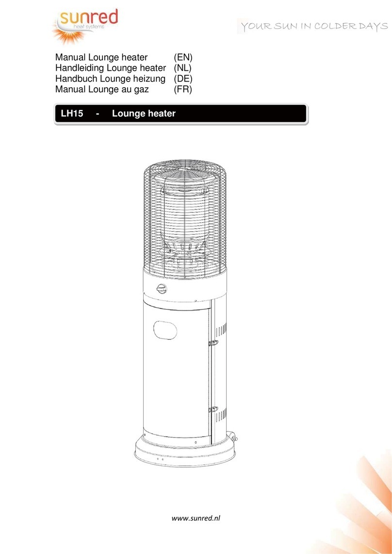
Space-Ray SR-AMC User manual


Table of contents
Other Space-Ray Heater manuals

Space-Ray
Space-Ray LTU40-N5 User manual

Space-Ray
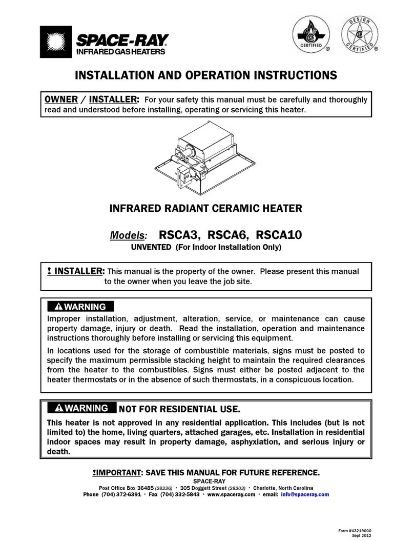
Space-Ray RSCA Series Installation instructions

Space-Ray
Space-Ray SWH User manual

Space-Ray
Space-Ray SBF 25 User manual

Space-Ray
Space-Ray PCA-SS 75 Owner's manual

Space-Ray
Space-Ray LTU Series User manual

Space-Ray
Space-Ray RSTP15C Installation and user guide

Space-Ray
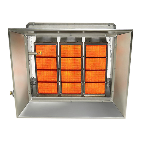
Space-Ray RFPA10C User manual
Space-Ray
Space-Ray DK30 User manual
Space-Ray
Space-Ray CB30-N5 Owner's manual

Space-Ray
Space-Ray RSTP15C User manual

Space-Ray
Space-Ray CBU09 User guide

Space-Ray
Space-Ray LRU25-HB Owner's manual

Space-Ray
Space-Ray Space-Ray ETS Series User manual

Space-Ray
Space-Ray SURA GSS15 User manual

Space-Ray
Space-Ray SUH-E User manual

Space-Ray
Space-Ray DK30 User manual

Space-Ray
Space-Ray SUH-S+ User manual

Space-Ray
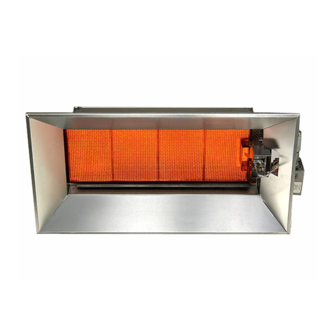
Space-Ray LTS 75-L5 User manual
Space-Ray
Space-Ray RSCA3 User manual
Popular Heater manuals by other brands

Brentwood
Brentwood H-C1601 Operating and safety instructions

HOMCOM
HOMCOM 820-279V70 Assembly & instruction manual

STIEBEL ELTRON
STIEBEL ELTRON ETS 200 Operating and installation instructions

Remington
Remington REM-18-PCH-B user manual

EUROM
EUROM GOLDEN 1500 Shadow user manual
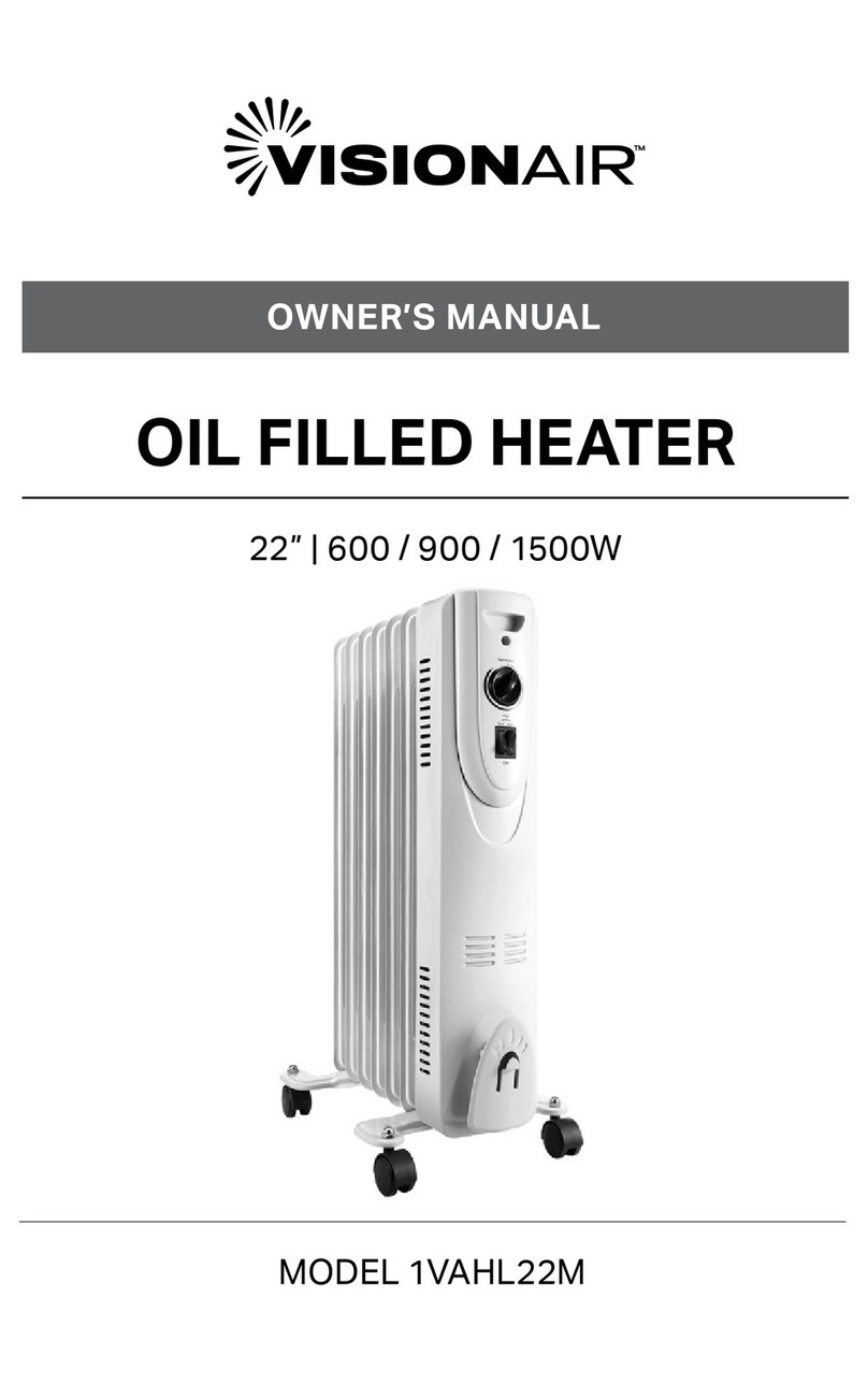
VisionAIR
VisionAIR 1VAHL22M owner's manual

Eterna
Eterna PAT2000W Safety and installation instructions

Elnur Gabarron
Elnur Gabarron IFT Series Installation instructions and user guide

Glen Dimplex
Glen Dimplex Quantum G6 Series manual
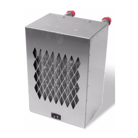
Dickinson
Dickinson Radex 1 Operator's manual
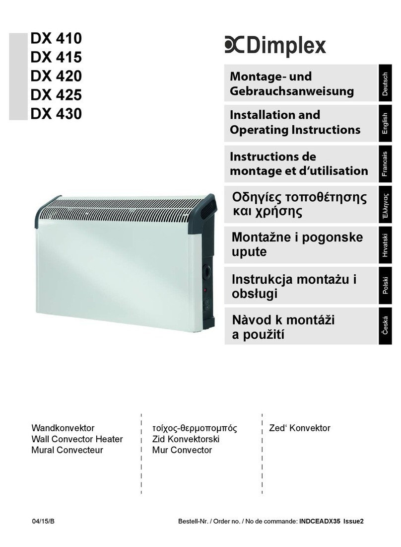
Dimplex
Dimplex DX 410 Installation and operating instructions

Toolland
Toolland TC78009 user manual
