Fcar F7S series User manual

FCAR Product Manual
1V1.1
Initial version: V1.0
Revision record
Date
Revision Content
Version
Revision
person
Reviewer
2018-07-10
Full update to existing
products
V1.1
Declaration
This manual is designed for the operation of FCAR products. Any company or
individual mustn't copy and back up this manual in any form (electronic
edition, mechanical edition, photocopying edition, video recording or other
form) without the written consent of Shenzhen FCAR Technology Co., Ltd.
This manual is only intended for use by professional vehicle service
technicians.
This manual only provides the operation method of FCAR products. We do
not assume any responsibility for the results caused by using the operation
method in other devices.
Regards to any accident caused by the operation of a user or a third party; or
any expenses and costs caused by the damage or loss of any device due to
users' misapplication, misusage, modification repair, or operation not
according to manual demands or device maintenance requirements, we do
not assume any responsibility.
This manual is written in accordance with the existing configuration and
functions of the product, and is subject to change without notice if the
product is added with new configurations and functions.

FCAR Product Manual
V1.1 2
If there is any question, please contact us as below:
Website: www.fcar.com
Headquarters: 8F, Chuangyi Bldg., No. 3025, Nanhai Ave., Nanshan, Shenzhen,
China
Factory: West 1F, Bldg. B, Hengchao Industrial Park, Tangtou North Ave., Bao'an,
Shenzhen, China
Tel: 0086-755-82904730
Fax: 0086-755-83147605
E-mail:marketing@szfcar.com
Registered trademark
FCAR has already registered trademark in China and several foreign
countries. In countries where any of the FCAR trademarks, service marks, domain
names, logos and company names, etc. are not registered, FCAR claims all rights
associated with non-registered trademarks, service marks, domain names, logos
and company names etc. Other products or company names, logos, service marks
etc. referred to in this manual still belong to their respective owners. Use of any
trademarks, service marks, domain names, logos of FCAR or any third company
without the written permission from the owner of the applicable trademarks,
service marks, domain names, logos or company names is prohibited.

FCAR Product Manual
3V1.1
FCAR Series Host Machine Maintenance and Use Cautions
Do not allow unauthorized disassembly.
Avoid strong impacts to the equipment.
Avoid proximity to any magnetic field.
Do not keep this machine in a high temperature environment for any length
of time.
Do not keep this machine in a low temperature environment for any length
of time.
Do not forcefully click on the screen or click the screen with sharp tools.
Do not use water and chemical solvents to clean the machine, please use a
soft clean cloth and neutral detergent instead.
Automobile Inspection Notes
Follow the standard safety rules of the auto repair industry to operate. Be
especially careful to avoid impact or damage caused by environmental
factors such as the surrounding pH, poison gas or high pressure
environment.
Vehicle battery fluid contains sulfuric acid, which is corrosive to the skin.
During the operation, avoid direct contact with the battery fluid, in
particular being careful not to splash into the eyes. Keep away from fire.
The engine exhaust gas contains a variety of toxic compounds, which one
should avoid breathing in. During the operation, park the vehicle in a
well-ventilated place.
When the engine is running, the temperature is very high; please avoid
contact with the water tank, exhaust pipe and other high temperature
components.
Before starting the engine, apply the handbrake and place the shift lever in
Gear Neutral (Manual Transmission) or P (Automatic Transmission) to avoid
sudden movements of the vehicle when starting the engine.
Before repairing the vehicle, apply the parking brake, engage the Neutral or
P range, and lower the driver seat’s glass doors.
If the engine can be started, warm-up the vehicle to normal temperature
(water temperature is about 80 °C), and turn off the auxiliary electrical

FCAR Product Manual
V1.1 4
appliances (such as air conditioning, lighting, sound, etc.).
Find the diagnostic seat of this car; check and confirm the diagnostic seat
lines are in good condition, connecting the main unit for diagnosis.
Otherwise, do not test, to avoid damage to the main unit. If necessary, use a
multimeter to measure the voltage of the diagnostic seat.
Instrument Use Notes
When using FCAR series products for testing, please be gentle and keep
them away from heat and electromagnetic fields, to avoid interference to
the main unit.
Do not use sharp tools to click the screen; the matched touch pen is
recommended.
When electrical components are energized, do not disconnect the circuit, to
prevent self-inductance and mutual inductance current damaging the
sensors and automotive ECU.
When electrical components are working normally, magnetic objects are
forbidden to approach the automotive control unit, otherwise the vehicle
control unit may be damaged.
Before disassembling the vehicle control unit or electrical components, turn
off the ignition switch for 1 minute.
Do not operate the diagnostic equipment when driving the vehicle, in order
to avoid traffic accident.

FCAR Product Manual
5V1.1
Table of contents
DECLARATION........................................................................................................... 1
1. INTRODUCTION..............................................................................................7
1.1 INTRODUCTION..............................................................................................7
1.2 F7S HOST STRUCTURE DESCRIPTION............................................................ 8
1.3 VCI BOX STRUCTURE DESCRIPTION.............................................................11
2. HOST ON/OFF AND FUNCTION MENU DESCRIPTION................................ 13
2.1 HOST CHARGING.............................................................................................. 13
2.2 BOOTING.......................................................................................................... 13
2.3 SHUTDOWN...................................................................................................... 14
2.4 INTRODUCTION TO EACH MENU OPTION....................................................... 14
3. VEHICLE DIAGNOSIS........................................................................................ 16
3.1 PRE-DIAGNOSTIC TECHNICAL REQUIREMENTS................................................17
3.2 VEHICLE CONNECTION..................................................................................... 18
3.2.1 CONNECT VCI BOX TO THE VEHICLE.................................................................... 18
3.2.2 HOST AND VCI BOX CONNECTION.................................................................. 21
3.3.3 VEHICLE TYPE SELECTION.............................................................................. 22
3.4 DIAGNOSES AND OTHER HIGH-LEVEL FUNCTION INTRODUCTION................ 25
3.5 DIAGNOSIS........................................................................................................27
3.5.1 READ FAULT CODE.......................................................................................... 29
3.5.2 ERASE FAULT CODE......................................................................................... 29
3.5.3 READ LIVE DATA............................................................................................. 30
Data stream waveform....................................................................................32
Data stream recording and comparison function........................................... 32
3.5.4 ACTUATION TEST............................................................................................. 34

FCAR Product Manual
V1.1 6
3.6 SPECIAL FUNCTION...........................................................................................37
3.7 GENERAL OBDII (FOR GASOLINE MODELS)..................................................... 38
4 DATA MANAGEMENT.......................................................................................... 39
5. REMOTE DIAGNOSIS...........................................................................................39
6. REFERENCE..........................................................................................................40
7. UPDATE............................................................................................................... 41
8. SETTINGS............................................................................................................ 41
9. DIAGNOSTIC CONNECTOR INTRODUCTION.......................................................47
WARRANTY CLAUSE............................................................................................... 53

FCAR Product Manual
7V1.1
1. Introduction
1.1 Introduction
FCAR F7S series product is an integrated automotive computer fault
diagnostic instrument aimed at the testing and diagnosis of gasoline, diesel,
natural gas and other electronic control systems according to the National 863
R&D program. The product is applicable to large and small service companies,
training institutions, automobile manufacturers, repair stations, diesel engine
manufacturers, mining machinery, petrochemical, energy and other enterprises.
Software of F7S is comprehensively configured, and vehicle data and
information in it are authoritative and fully meet the strict requirements of
customers' detection breadth and depth. The software covers thousands of
domestic and imported vehicle model data, and provides a powerful help system
with maintenance information, enabling users to deal with the problems in
practical work easily and quickly, thereby increasing the efficiency and technical
level and reflecting the advantage of professional level quality.

FCAR Product Manual
V1.1 8
1.2 F7S host structure description
Serial
number
Name
Description
①
Power supply indicator
Charge indicator
②
Microphone port
Voice input port
③
Light sensor
Outside light intensity induction
Host parameter
F7S series products are equipped with two configurations of parameter at
the factory, which are subject to the configuration you purchased. The following
are two configurations of parameter information:
Configuration A:
System
Android 4.3 based multitasking operating system
Processor
Freescale Industrial Grade 4 Core 1.2GHz Architecture
Processor
Touchscreen
10.1” Multi-touch capacitive screen TP thickness: 1.1mm

FCAR Product Manual
9V1.1
Memory
2GB RAM & 32GB ROM, support 32GB TF memory card
Connection
WiFi&Bluetooth 2.0/4.0
Camera
Postpositioned 5 million pixels camera, auto focus support
COM
RJ45, HDMI, USB2.0, TF card slot, headphone jack, power
connector
Size
320*210*30mm
Configuration B:
System
Android 5.1 multitasking operating system
Processor
Cortex-A17 RK3288 quad-core processor, 1.8GHz architecture
processor
Touchscreen
10.1” Multi-touch capacitive screen, TP thickness: 1.1mm
Memory
2GB RAM & 32GB ROM, support 32GB TF memory card
Connection
WiFi &Bluetooth 2.0/4.0
Camera
Postpositioned 13 million pixels camera, auto focus supported
COM
RJ45, HDMI, USB2.0, TF card slot, headphone jack, power
connector
Size
320*210*30mm

FCAR Product Manual
V1.1 10
Serial
number
Name
Description
④
TF card slot / 3.5
headphone jack
Storage TF card location / headphone jack
⑤
Vents
Used to cool the F7S host to avoid overheating
⑥
External speaker
port
For external sound playback
⑦
Camera
Used to take a photo or record a video
⑧
Flashing light
Used to provide light when the light is weak
⑨
DC power port
Used to charge or energize the F7S host
⑩
RJ45 port
For network connections
○
11
USB port (B
shape)
Device interface: used to connect to a
computer and use the F7S host as a U disk.
○
12
USB port
Host interface: used to connect F7S host to the
VCI or connect to the USB flash drive.
○
13
HDMI port
Standard HDMI interface: used to connect to TV
HD output
○
14
Power switch
Used to switch on or off F7S host, or lock the
screen

FCAR Product Manual
11 V1.1
1.1 VCI box structure description
Serial
number
Name
Description
①
Power supply indicator
Lighted on when the power is supplied
(connected to the car)
②
Diagnostic indicator
Lighted on when communicating with
the vehicle
③
Bluetooth indicator
Lighted on when connected to the F7S
Host machine
④
USB indicator
Lighted on when connected to F7S host
FCAR Product Manual
V1.1 12
Serial
number
Name
Description
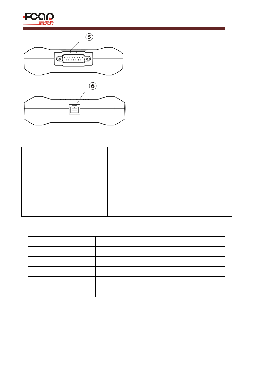
⑤
DB15 port
Connected to the main test line, and
connected to the vehicle via the diagnostic
connector
⑥
USB port (B shape)
Connected to F7S host or used to upgrade the
VCI box
VCI box parameters
Processor
Cortex-M3 Microcontroller
Frequency
100MHz
Processor model
LPC1768
FLASH EPROM
512KB
Memory
64KB
Bluetooth
Support Bluetooth 2.0, Bluetooth 4.0

FCAR Product Manual
13 V1.1
2. Host On/off and function menu description
2.1 Host charging
Host can be charged in following ways:
Power adapter: Plug one end of the AC/DC power adapter to the DC power port
of the host and then connect the other end to the wall socket. The power adapter
can be used to charge the built-in battery pack.
Note! Voltage of the power supply should be within the scope of the product host.
Exceeding the range may cause damage to the product.
2.2 Booting
Press and hold the F7S host power switch (about 3 seconds) to power on host,
the following welcome interface will pop up, and then system starts working.

FCAR Product Manual
V1.1 14
2.3 Shutdown
All vehicle communication must be terminated before shutting down the F7S
diagnostic equipment. Vehicle's electronic control module would go wrong if
forced shutdown during communication, please exit all diagnostic applications
before shutting down.
The shutdown steps are as follows:
1) Short press F7S host power switch (about 2 seconds)
2) Click [Shutdown] in the pop-up prompt to close F7S host.
2.4 Introduction to each menu option
After the system is powered on, enter the following main menu:
1. Status icon: is the default icon of the standard Android operating system
2. Toolbar (see Table 1)
3. Main menu (see Table 2)

FCAR Product Manual
15 V1.1
4. Guide bar (see Table 3)
Tip: It is recommended to lock the screen whenever you are not using the
device to protect your system information and save battery power. Slightly click
the power/lock screen button once, the screen will be automatically locked.
Excessive force or long press may cause the button to malfunction or enter the
shutdown interface.
Table 1: Toolbar
Icon
Function name
Function description
VCI
Connection
VCI box connection and status display (always
available throughout diagnostic operation)
Screenshot
One click to capture the current visual screen
(always available throughout the diagnostic
operation)
Settings
"Settings" function shortcut
Table 2: Main Menu
Icon
Function name
Function description
Diagnosis
Car diagnostic procedures, see section 3
VCI
connection
Establish and manage communication connections
with VCI devices, see section 3
Data
management
For browsing and managing data files stored, see
section 4
Remote
Run this program to establish remote assistance
with FCAR after-sales technical team, see section 5
Reference
guide
Provide help information such as equipment usage
instructions, maintenance assistance, trouble code
inquiry, etc. See section 6 for details.
Update
Online upgrade of system software, model
software, etc. See section 7 for details.

FCAR Product Manual
V1.1 16
Settings
Set up and view system information, see section 8
for details.
Table 3: Navigation Bar
Icon
Function name
Function description
Back
Return to last interface
Homepage
Return to the main interface of the Android
system
Recently used
program
Display the list of recently-used program
thumbnails list, click on the program thumbnail
to open the program, and swipe up the program
thumbnail to close the program
Website
information
With internet connected, click it to enter FCAR
official website
3. Vehicle diagnosis
Through having established data connection with the vehicle's electronic
control system that has been connected to the VCI device, the diagnostic program
can read vehicle diagnostic information, check the data stream, and perform
actuation test and other functions.
To establish good communication between the diagnostic program and the
vehicle, you need to do as below:
1) Connect the VCI box to the vehicle diagnostics socket and supply the
power;
2) Establish communication between VCI and F7S host via Bluetooth
pairing or USB data cable;
3) Check VCI connection status in the upper right corner of the screen
(see 3.2.2). The vehicle diagnosis can be performed after the
connection.
FCAR Product Manual
17 V1.1
Vehicle diagnosis:
1) Establish a good communication between the diagnostic program and
the vehicle under test, see 3.2
2) Select vehicle type, see 3.3.
3) Perform vehicle diagnosis by “Auto Scan” all systems of the vehicle or
manually selecting and detecting a designated control unit. For details,
see 3.5.
Here we make the detailed instructions.
3.1 Pre-diagnostic technical requirements
3.1.1 Equipment Requirements
F7S series automotive computer fault diagnostics is equipped with a host
and various test connectors when leave factory. In testing, please select
appropriate test connector according to the type of vehicle diagnosis socket.
3.1.2 Vehicle requirements
Turn ignition switch to gear ON;
Vehicle battery voltage should be between 11~14V or 24~27V (subject to the
vehicle's power supply)
Accelerator pedal is in OFF state, that is, the idle coupling point;
Ignition timing and idle speed value should be within the standard range,

FCAR Product Manual
V1.1 18
and the water temperature and transmission oil temperature are in the
normal working temperature (water temperature 90~110°C, transmission oil
temperature 50~80°C);
Diagnostic line is connected properly.
3.1.3 Maintenance technician requirements
Must have a basic knowledge of automotive electronics;
Understand the basic operation methods of this product and familiarize with
this manual;
Basically distinguish whether it is a mechanical fault or an electronic control
fault from the vehicle fault phenomenon tested;
Learn about the vehicle's origin, year of production, model, engine model
and more.
3.2 Vehicle connection
3.2.1 Connect VCI box to vehicle
Before VCI box connected to vehicle, it is necessary to judge whether the
diagnostic seat of the test vehicle is a standard OBD-II port or a non-standard
FCAR Product Manual
19 V1.1
OBD-II port.
Vehicles compatible with the OBD-II management system can be connected
to vehicle diagnostics socket and supplied with power only with one
standard OBDII-16 connector;
Vehicles that are not compatible with the OBD-II management system need
to select the corresponding connector; some other vehicles need to supply
power to the VCI box through other power sources of the vehicle.
Here we make the operating instruction regards to these two connection modes
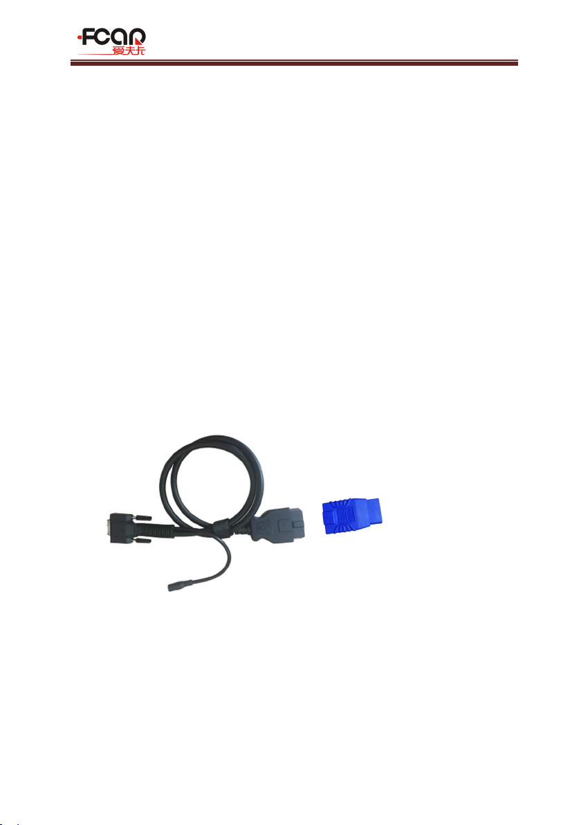
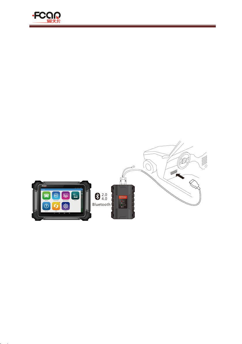
Standard OBD-II port connection
Vehicles connected to standard OBD-II port just need to connect the
all-in-one main test wire rather than other connectors, as shown in Figure 3.2-2:
Figure 3.2-2 Connection of standard-OBD-II socket
Instructions:
1) Determine the location and the port of the diagnostic seat;
2) Connect one end of main test cable to the DB15 connector of the VCI box
and lock the fixing bolt;
3) Connect the other end of the main test line to the vehicle diagnostic seat;
4) At this time, the VCI box is powered by the vehicle diagnostic seat, and the
power indicator light is on.
Note: After the test is completed, please rotate the fixing bolts and then gently
FCAR Product Manual
V1.1 20
unplug the main test line to avoid damage to the diagnostic port.
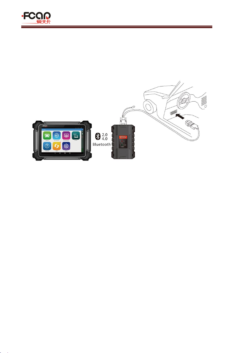
3.2.2 Non-OBD-II port Connection
Vehicles connected to non-OBD-II interfaces need to connect the main test leads
to their corresponding dedicated connectors, as shown in Figure 3.2-2:
Figure 3.2-2 Connection of non-OBD-II interface
Instructions:
1) Determine the location, the port, and whether need to be connected to the
external power source for the diagnostic seat;
2) Connect one end of the main test lead to the DB15 connector of the VCI box
and lock the fixing bolts;
3) Connect the other end of the main test line to a dedicated adaptor
corresponding to the vehicle;
4) Connect the dedicated connector that is connected to the main test cable to
the vehicle diagnostic seat;
5) At this time, VCI box is powered by the vehicle diagnostic socket, and then
power indicator light is on (if it is not lit, it may be because the vehicle
diagnostic seat is not energized, you can energize the VCI box by the
cigarette lighter or the battery clip).
Other manuals for F7S series
2
Table of contents
Other Fcar Diagnostic Equipment manuals


