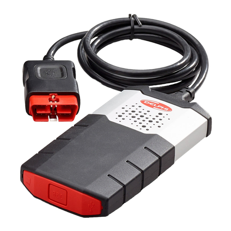
Autodiagnos PC Pro User manual

PC PRO
User manual

Part Number A37MAN
EN - Issue 1 © Autodiagnos 2010
PC PRO
User Manual
Part Number A37MAN
EN
Issue 1
© Autodiagnos 2010


Contents
i
Quick reference guide
Introduction............................................................................................. 1
Product support hotline........................................................................... 2
Software CD ........................................................................................... 2
Hardware configuration .......................................................................... 3
Configuring the PC ................................................................................. 4
Getting started........................................................................................ 6
Using Autodiagnos PC Pro..................................................................... 8
Operating instructions
Overview............................................................................................... 10
Using Autodiagnos PC Pro................................................................... 11
Troubleshooting.................................................................................... 23
Cable identification ............................................................................... 24
Licence Agreement
Licence Agreement for Autodiagnos PC Pro........................................ 27
Equipment disposal
Disposal of equipment.......................................................................... 29
Disposal of batteries............................................................................. 29


Quick reference guide
1
Quick reference guide
Introduction
Congratulations on choosing the Autodiagnos PC Pro diagnostic system. The system
enables information to be extracted from various vehicle control modules when
connected via the vehicle’s diagnostic connector.
Bothpre-EOBD(European On-BoardDiagnostics) andEOBD-compliantvehiclesare
covered.
Note: All post 2000 MY petrol cars and post 2004 MY diesel cars should conform to
the EOBD standard.
Overview
The kit includes the following items.
1. Carry case with foam insert.
2. Vehicle Interface.
3. USB cable.
4. J1962 OBD cable.
5. CD.
6. Quick reference guide.
7. Power supply unit.
7
CR0239
1
5
6
2
4
3

Quick reference guide
2
Product support hotline
Alternatively, visit the Autodiagnos website at www.autodiagnos.com.
Note: To avoid delay, always quote the serial number of the Vehicle Interface when
requesting support.
Software CD
Installation instructions
1. Insert the CD into the CD drive.
2. The installation on the CD should auto-run. If it fails to do so, navigate to the CD
drive in Windows Explorer and double-press the ‘Setup.exe’ icon.
3. Follow the on-screen instructions to install the application, accepting all options
provided to achieve the default installation.
4. Restart the PC before first use.
Tel: +44 (0)844 665 7623.
Fax: +44 (0)844 665 7603.

Quick reference guide
3
Hardware configuration
Vehicle Interface (VI)
This component acts as an interface between the vehicle being tested and the
software installed on a PC.
Externally, the VI has a number of connectors, but no switches or buttons. It is
operated by the user from the PC screen.
LEDs alert the user to the operational status of the VI.
1. Communicating with vehicle systems.
2. Power.
3. USB connection status.
4. Bluetooth connection status.
AU0022
2
2
2
4
4
3
3
1
1

Quick reference guide
4
Configuring the PC
ThePCmustbe set up to recognise the VehicleInterface(VI).Thereare two methods
of connecting the VI:
• USB - Hard wired,
• Bluetooth - Wireless.
USB is the default connection method setting.
USB - Hard wired
Follow the procedure below to connect the PC to the Vehicle Interface (VI) using a
USB cable.
1. From the ‘VI Mode’ drop-down list on the ‘Settings’ tab, select ‘USB’.
2. Connect one end of a USB cable to the VI and the other end to a USB port on
the PC.
3. The drivers will install automatically. Press ‘Continue Anyway’ when prompted.
The operating system will display a notification when the process is complete.
Bluetooth - Wireless
Follow the procedure below to connect the PC to the Vehicle Interface using wireless.
1. Follow the instructions provided with your laptop or Bluetooth dongle to set up a
wireless connection to the Vehicle Interface. The Bluetooth device name is
‘Vehicle Interface’ and if requested enter the PIN code 1234.
2. Once the connection has been set up a COM port number will be displayed.
Make a note of this number.
3. From the ‘VI Mode’ drop-down list on the ‘Settings’ menu, select ‘Bluetooth’.
4. From the ‘Bluetooth Port’ drop-down list select the COM port number recorded in
step 2.
3
3
3
CR0236

Quick reference guide
5
Settings
1. Language settings
2. Vehicle Interface (VI) settings
3. Vehicle Interface (VI) configuration
4. Company settings
5. Product information
From the ‘Settings’ screen, the software language can be selected. Please note the
Vehicle Interface (VI) must be connected to both the PC and a vehicle in order to
change the software language. This process may take up to twenty minutes.
The method of communication with the VI can also be changed. ‘USB’ is the default
communication method.
1
1
1
3
3
2
2
4
4
5
5
AU0077

Quick reference guide
6
Getting started
Note:If the vehicle doesnot have a J1962 cable socket,the appropriate manufacturer
diagnostic cable will be required. See ‘Cable identification’, page 24.
USB Connection
1. Connect the EOBD cable to the Vehicle Interface.
2. Connecttheappropriatemanufacturerdiagnosticcable ifnecessary totheEOBD
cable.
3. Connect the diagnostic cable to the vehicle’s diagnostic socket.
4. Connect the vehicle interface to the PC USB port.
5. Double-press the Autodiagnos PC Pro icon on the desktop to launch the
software.
CR0237

Quick reference guide
7
Bluetooth connection
1. Connect the EOBD cable to the Vehicle Interface.
2. Connecttheappropriatemanufacturerdiagnosticcableifnecessarytothe EOBD
cable.
3. Connect the diagnostic cable to the vehicle’s diagnostic socket.
4. Double-press the Autodiagnos PC Pro icon on the desktop to launch the
software.
CR0238s

Quick reference guide
8
Using Autodiagnos PC Pro
1. Menu items
2. Vehicle/System selection
3. Exit the application
4. Restart vehicle selection
5. Return to previous screen
6. View technical data (where installed)
7. View cable images
8. View connector locations
The ‘Vehicle Selection’ screen is displayed when Autodiagnos PC Pro is started.
Each screen has a number of icons and buttons which control the diagnostic
functions.
Diagnostic cable drawings and connector locations can be viewed by pressing button
7 or 8 respectively.
Note: All tabs, buttons and icons are highlighted when available for use.
666
55
2
11
33
44
7788
AU0075

Quick reference guide
9
Starting a diagnostic session
1. From the ‘Vehicle Selection’ screen, select the relevant vehicle and then system
for diagnosis.These options will appear over a number of consecutive screens.
2. Selecting a system will automatically prompt the software to begin
communication.
3. The communication LED on the Vehicle Interface will begin to flash, confirming
that the Autodiagnos PC Pro software is connecting to the system.
4. When the vehicle is ready for diagnostic tests, the diagnostic menu items on the
left hand side of the screen become enabled.
AU0073s

Operating instructions
10
Operating instructions
Overview
The screens have a number of icons and buttons which control the diagnostic
functions.
This guide explains the common controls and information screens.
In the graphic below, the ‘Vehicle Selection’ screen is selected.
Note: All tabs, buttons and icons are highlighted when available for use.
1. Menu items
2. Vehicle/System selection
3. Exit the application
4. Restart vehicle selection
5. Return to previous screen
6. View technical data
7. View cable images
8. View connector locations
666
55
2
11
33
44
7788
AU0075

Operating instructions
11
Using Autodiagnos PC Pro
Selecting a vehicle for testing
1. Menu items
2. Vehicle/System selection
3. Exit the application
4. Restart vehicle selection
5. Return to previous screen
6. View technical data
7. View cable images
8. View connector locations
From the ‘Vehicle Selection’ screen, select the relevant manufacturer, model and
then system for diagnosis. These options appear over a number of consecutive
screens.
Press button 2 to restart the vehicle selection and return to the list of vehicle
manufacturers.
Press button 1 to return to the previous screen.
Diagnostic cable drawings and connector locations can be viewed by pressing button
7 or 8 respectively.
Note: All tabs, buttons and icons are highlighted when available for use.
666
55
2
11
33
44
7788
AU0075

Operating instructions
12
Selecting a vehicle system for testing
Once a vehicle has been selected, the screen will show the systems available for
testing.
Selecting a system will automatically prompt the software to begin communication.
The communication LED on the Vehicle Interface will begin to flash, confirming that
the Autodiagnos PC Pro software is connecting to the system.
AU0072

Operating instructions
13
When the vehicle is ready for diagnostic tests, the diagnostic menu items on the left
hand side of the screen become enabled.
AU0080

Operating instructions
14
1. Exit the application
2. Restart vehicle selection
3. Return to previous screen
4. View technical data
5. Options / results display
6. Scroll up / down
7. Back
8. System dependent features
9. Jobsheet function
10. Confirm / next
Some vehicle systems will be displayed in a different format to the standard layout.
The options and results will be displayed within a system window which is controlled
by on-screen buttons.
The ‘scroll up / down’ buttons 6 are used to navigate through options and results. If
information spans multiple screens, it will be indicated by a series of dots.
44
1
2
3
5
6
7 9 1010
8
AU0078
4
1
2
3
5
6
7910
8

Operating instructions
15
The ‘back’ button 7 returns to the previous screen.
The ‘confirm / next’ button 10 will confirm a selection or move to the next screen.
The ‘system dependent feature’ buttons 8 vary in their application and should only be
used when instructed to do so by Autodiagnos PC Pro.
Reading and clearing fault codes
1. Refresh fault code list
2. Clear fault codes and freeze frame data
3. View Autodata technical data
4. View Vivid technical data
When the vehicle system has been identified, the ‘Fault Codes’ menu item will
become enabled where supported. This will allow fault codes to be read from the
selected system. It is also possible to clear fault codes from the system.
Press button 1 to refresh the list of fault codes.
Press button 2 to clear all fault codes and freeze frame data.
11
22
33
44
AU0073
Other manuals for PC Pro
1
Table of contents
Other Autodiagnos Diagnostic Equipment manuals
