Span-America PressureGuard APM2 User manual

P10331
OWNER’S MANUAL
PressureGuard®APM2
and
PressureGuard®APM2 Safety Supreme
Span-America Medical Systems, Inc.
Greenville, SC 29615
800-888-6752

P10331

P10331
TABLE OF CONTENTS
DOCUMENT SYMBOLS.................................................................................................................................................1
INTRODUCTION .............................................................................................................................................................2
DESCRIPTION
INDICATIONS FOR USE
MODES OF OPERATION
CONSTRUCTION AND DESIGN FEATURES..........................................................................................................4
CONSTRUCTION AND DESIGN FEATURES DESCRIPTIONS.........................................................................5
DIRECTIONS FOR SET-UP..........................................................................................................................................6
CONTROL UNIT FUNCTIONS ....................................................................................................................................8
ELECTROMAGNETIC OR OTHER INTERFERENCE .......................................................................................10
POWER LOSS / PATIENT TRANSPORT ............................................................................................................10
HEAD-OF-BED ELEVATION....................................................................................................................................10
TROUBLESHOOTING PATIENT COMPLAINTS ...............................................................................................11
GENERAL DIRECTIONS............................................................................................................................................11
BED LINENS
INCONTINENCE PADS
BED RAILS
CPR
STORAGE AND TRANSPORTATION
ENVIRONMENTAL CONDITIONS FOR USE
SERVICE
WARRANTY
USE IN WOUND CARE
CLEANING
ROUTINE INSPECTION OF POWER CORDS AND MATTRESS
SPECIFICATIONS.........................................................................................................................................................15
TROUBLE SHOOTING GUIDE.................................................................................................................................17
TECHNICAL DESCRIPTION.....................................................................................................................................19
IN-HOME STYLE MODELS, USAGE NOTES.......................................................................................................19
APPEDIX A: EMC INFORMATION.........................................................................................................................20
PREVENTIVE MAINTENANCE AND REPAIR LOG .........................................................................................23

P10331

1
P10331
Document Symbols
This manual contains different typefaces and symbols to make the content easier to read
and understand:
Standard text –used for regular information.
Boldface text –stresses a word or phrase.
NOTE: - sets apart special information or important instruction clarification.
The symbol below identifies a WARNING or CAUTION:
-A WARNING identifies situations or actions that may have an effect on patient or
user safety. Ignoring a warning could cause patient or user injury.
-A CAUTION points out special procedures or precautions that persons must obey
to avoid equipment damage.
The symbol below identifies an ELECTRICAL SHOCK HAZARD WARNING:
EN 60601-1-2 Electromagnetic Emissions
IEC 60601-1 Electrical Safety

2
P10331
INTRODUCTION
PRESSUREGUARDAPM2 SERIES
Air therapy support surface
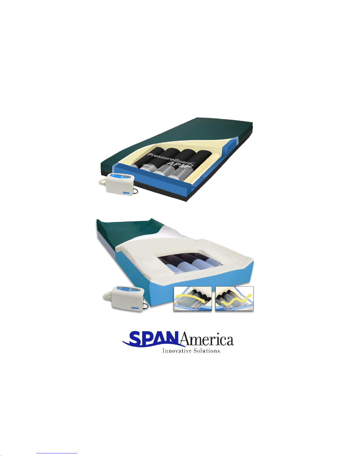
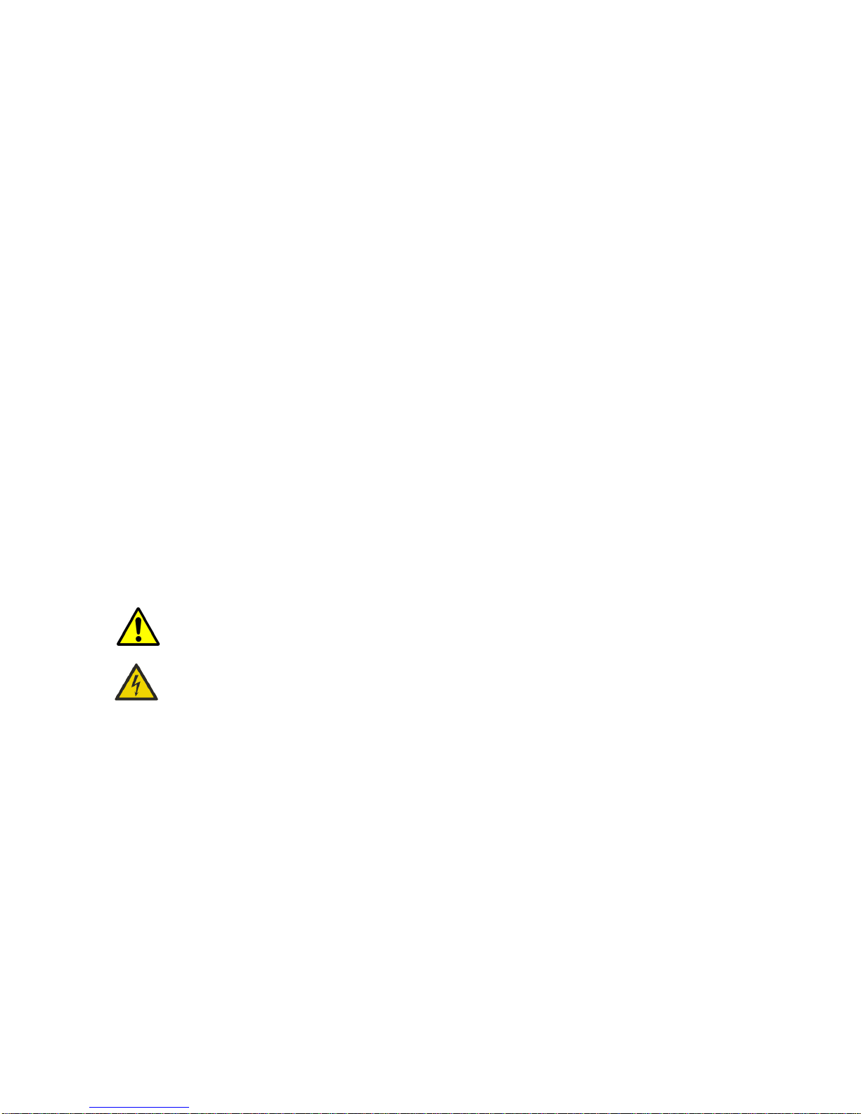
DESCRIPTION: The system consists of a foam shell with a high-density foam topper
serving as the support surface underneath the patient. The foam shell also includes
Safety EdgeTM bolsters at the sides of the mattress, providing added patient stability and
positioning. The system also includes the unique Heel Slope™feature, designed to further
reduce pressure for the sensitive heel area. Within the foam shell is housed the inflation
system, consisting of air cylinders which run lengthwise within the mattress. The air
control unit connects to the mattress at the patient foot-end.
MODES OF OPERATION: The PressureGuard®APM2 series provides options of
alternating pressure, basic lateral rotation, powered flotation and auto-firm.
INDICATIONS FOR USE: PressureGuard® APM2 models are powered, flotation therapy
mattresses providing a pressure management surface for the prevention and treatment
of pressure ulcers. The lateral rotation mode is indicated for use as a preventive tool
against further complications associated with critically ill patients or immobility.
CONTRAINDICATIONS:
Not recommended for patients for whom rotation or turning is contraindicated, such as,
but not limited to, unstable spinal cord injury, unstable skeletal fractures requiring
immobilization and/or skeletal traction, physician orders prohibiting rotation, or severe
posterior burns requiring skin grafts.
The PressureGuard®APM2 series is not for use by those with unstable
spinal cords. Patient injury could occur.
WARNING - To reduce the risk of electrocution
READ ALL INSTRUCTIONS BEFORE USING THIS UNIT.
1. Always unplug this unit immediately after using.
2. Do not operate near water.
3. Do not place or store product where it can fall or be pulled into a tub or sink.
4. Do not place in or drop into water or other liquid.
5. Do not reach for a product that has fallen into water. Unplug immediately.
6. Use this unit only for its intended use as described in the operating instructions.
7. Never operate this product if it has a damaged cord or plug, if it is not working
properly, if it has been dropped or damaged, or dropped into water. Contact Span-
America Medical Systems, Inc., for return of control unit for examination and repair.
8. Keep the cord away from heated surfaces.
9. Never drop or insert any object into any opening or hose.
10. Do not use outdoors.

3
P10331
To reduce the risk of burns, electrocution, fire or injury to persons:
1. Use this unit only for its intended use as described in the operating instructions.
2. Never operate this product if it has a damaged cord or plug, if it is not working
properly, if it has been dropped or damaged, or dropped into water. Return the
unit to Span-America Medical Systems, Inc. for examination and repair.
3. Keep the cord away from heated surfaces. Discontinue use if power cord is
damaged or worn.
4. Never drop or insert any object into any opening or hose. Keep away from sharp
objects.
5. Do not use outdoors.
6. Possible explosion hazard if used in the immediate proximity of flammable gases
(risk of explosion).
7. Use only original spare parts and consumables.
8. Keep power cord away from heated surfaces.
9. Plug this product into a correctly grounded outlet only.
10. Before cleaning, unplug unit from its power source. Failure to do so could result in
personal injury or equipment damage.
11. Do not use harsh cleansers, solvents, or detergents. Do not expose the unit to
excessive moisture. Equipment damage could occur.
Warning: This product contains/may contain chemicals known to the state of California to cause
cancer and/or birth defects or other reproductive harm.

4
P10331
Construction and Design Features
Cover
Foam topper with
Geo-Matt design
Air cylinders
Safety Edge™ bolster
Mattress toggle switch
Standard APM2 model
Safety Supreme model
(showing raised perimeter)
Shear Transfer Zones™ design (standard APM2 model only)
(U.S. Patent # 8,438,682)
In addition to the Geo-Matt® segmented top surface, Span-America’s exclusive
Shear Transfer Zones™design provides an additional measure of shearing
protection in the form of the silicone-coated, shear-minimizing fabric bands located
on the underside of the bi-directional stretch cover.
This Shear Transfer Zones design helps:
Prevent heels, sacrum, and scapula from “digging into” surface
“Glide” user back to original position following HOB elevation
Protect against damaging effects of micro shear, macro shear, and rotational
(pivot-induced) shear
Provide patient stability by transferring shear to more shear-tolerant anchor
points
Digital control unit

5
P10331
Construction and Design Features
Illustration Descriptions
*Silver3® is a registered trademark of Dartex Coatings, Ltd.
www.dartexcoatings.com • email: sales@dartexcoatings.com • Tel: +44 1159 837 676
Uses Smith & Nephew Extruded Films technology www.snef.co.uk • email: snef@smith-nephew.com • Tel: +44 1430 440 757
The air-cylinder inflation system and the foam shell work in concert to maintain low interface pressures
throughout the surface, making the mattress effective for prevention and treatment of pressure ulcers.
[Illustration item ①]
Covers:
PressureGuard®APM2
PressureGuard®APM2 Safety
Supreme
Both models include replaceable, zippered covers made with fabrics that are
anti-microbial, flame-resistant, fluid-impervious, tear-resistant, and have a
low moisture vapor transmission rate (MVTR). Covers easily wipe clean
with standard, hospital-grade cleaners.
Standard cover of APM2 model is made with bi-directional stretch top fabric
and includes proprietary “Shear Transfer Zones” (patent pending) design
that creates shear-minimizing bands beneath heels, sacrum and scapula. See
bottom of page 4 for illustration and complete description.
Standard cover of Safety Supreme model is non-stretch, barrier fabric
with pleated design to allow full integration with surface while minimizing
hammocking.
Both models also available with Silver3®silver-infused stretch
fabric, a proprietary fabric technology that protects surface from
stains, odor-causing bacteria, mold and mildew.*
Foam Topper:
[Illustration item ]
The Geo-Matt®style foam topper is a high density, medical grade foam. The
unique geometric design consists of over 800 individual cells, each of which
acts individually to redistribute pressure, to reduce heat and moisture
buildup on the skin, and to reduce shear to underlying tissues. This foam
topper is 2" in height and includes the unique Heel Slope™ feature, designed
to further reduce pressure for the sensitive heel area.
Safety EdgeTM Bolsters
[Illustration item ]
The patented Safety EdgeTM consists of the contoured foam bolsters around
the sides and ends of the mattress for added patient stability in sitting and
lying down.
Air Cylinders:
[Illustration item ]
The inflation system consists of four urethane air cylinders in standard
models that run head to foot underneath the body and the foam topper.
These cylinders perform the alternating pressure therapy, and the lateral
rotation therapy. Cylinders inflate and deflate in a fixed 10-minute cycle.
The cycles and inflation levels are designed to provide and maintain low
interface pressures throughout the mattress, and to redistribute peak
interface pressure points during the alternating cycle.
Mattress Toggle Switch
[Illustration item ]
The toggle switch changes modalities from alternating pressure to lateral
rotation. The switch is located under a velcroed fabric flap on the side of the
mattress at the foot end.
Control Unit:
[Illustration item ]
Model 5900 Digital Control Unit

6
P10331
DIRECTIONS FOR SET-UP
1. Place the PressureGuard®mattress on the bed frame with the airline connectors at
the foot end of the bed. The mattress has a gray vinyl side that should be down on the
bed frame, and a green or silver fabric side that should be face up toward the patient.
In-home models, (available for standard APM2 models only) have a dark blue fabric
that should be face up toward the patient. Confirm that the bed frame is appropriate
for use with the mattress, and that the length and width of the mattress are
appropriate for the frame. Place directly on a healthcare bedframe only, never on top
of another mattress.
WARNING: The fit of the mattress to the bed frame is important. Minimizing
spaces or gaps between the mattress and frame will help prevent patient
entrapment issues.
2. Hang the control unit on the foot board
at the end of the bed using fold-out
hangers (Figure A). Connect airlines to
control unit by pressing quick
connector into port on the side of unit.
“Triangle” symbol should face front.
(Figure B) Audible “click” indicates
secure connection.
Note: If desired, hanger lock strip
(included, item # P10064, Fig. C) can be used to help hold control unit more snugly in place
on thin footboards such as those often found on home health care beds. To use, place the
strip in position around the hanger hooks as shown in Figure D.
Figure C
Figure D
3. Connect the ends of the air lines with two right angle male connectors (Figure E) to the
ports on the side of the mattress. Ports (Figure F) are located beneath a fabric flap (Figure
G) near the right front corner of the mattress. Ensure that the airlines are not kinked or
twisted. Press connectors into ports until you hear an audible “click” for each. Press flap
closed.
Figure A
Figure B

7
P10331
Figure E
Figure F
Figure G
4. Ensure that the Toggle switch is in the “Alternating Pressure” position.
5. Ensure that green On/Off switch at side of control unit is “Off”. Plug power cord into
wall outlet. Press On/Off switch “ON”.
Never thread airline through mechanical parts of the bed or bed rails where normal bed movement
may damage the airlines, power cord or the control unit itself. Check to be sure the motion of the bed
does not interfere with the airlines, power cord or plug.
Always plug the power cable securely into the wall outlet. Make sure the wall-mounted outlet will
accommodate a heavy duty or hospital-grade plug and that the outlet is in good working order. The
plug of the power cord should fit tightly into the wall outlet. The plug body, the wall outlet, and the
wall plate should not be cracked or chipped. The plug blades should be securely retained in the plug
body. The ground pin of the plug should be intact and secure.
Do not connect the power cord to an extension cord or to a multiple outlet strip. If the use of extension
cords or multiple outlet strips cannot be avoided, use only heavy duty or hospital-grade connectors
that are approved by the facility engineering department. Multiple outlet strips should be mounted on
a fixed object to reduce the risk of liquid spills and physical damage. In addition, if multiple-receptacle
outlet boxes are used, they also should be protected from the risk of liquid spills and physical damage.
All extension cords and multiple outlet strips should be tagged and inspected routinely.
Do not cover the power cord with a rug or carpet. Rugs or carpets can prevent normal air flow, which
can lead to greater heat built-up. Place the cord in a low or no traffic area. Check to be sure the
motion of the bed does not interfere with the bed’s power cord or plug.
6. When power switch is turned to ON, the unit will power up in “Auto Firm” mode and
begin performing a system check. This fills the air system completely, in order to
confirm the proper connection and function of both the mattress and the control unit
prior to a patient being placed on the surface. If the mattress is completely empty of
air, this can take as long as 20 minutes. Since this is rarely the case, however, this
typically takes no more than 2.5 minutes.
7. System will remain in “Auto Firm” mode until this process is complete. “Low
Pressure” indicator light and audible alarm will remain on as well. Audible Alarm can
be disengaged during this process by pressing the Audible Alarm On/Off button.
8. When system check is complete, the control unit will revert to previous comfort
setting and “Alternate” mode. Low Pressure indicator light will turn off. System is
now ready to be set for the next user.
NOTE: If “Low Pressure” remains on after 30 minutes, call for service.

8
P10331
5900 Control Unit
Functions
Comfort Level Selection:
Allows selection of air cylinder firmness within a
relatively small range. Press “Softer” or “Firmer”
button to achieve desired setting. Begin in softest
setting, then adjust for comfort as desired.
Mode Selection: Press button to select “Alternate”, “Float”, or “Auto Firm”.
“Alternate”mode: Creates an “A-B” sequence of
inflation and deflation of the mattress’s four air
cylinders designed to change loading across the
surface in a 10-minute cycle. Use the toggle
switch on the side of the mattress to select
between two patterns of alternation:
Lateral Rotation therapy: With mattress toggle
switch set to “Lateral Rotation”, two air cylinders
on one side inflate, while the two on the opposite
side deflate, gently rotating the patient
approximately 20 degrees to one side. After
approximately 5 minutes, the inflation pattern
reverses and the patient is rotated to the opposite
side.
Alternating Pressure therapy: With mattress
toggle switch set to “Alternating Pressure”, air
cylinders 1 and 3 inflate while 2 and 4 deflate.
After approximately 5 minutes, the pattern
reverses.
Pictured: Mattress toggle switch set to
“Lateral Rotation”
Pictured: Mattress toggle switch set to
“Alternating Pressure”

9
P10331
5900 Control Unit
Functions Continued
“Float” (powered flotation therapy) mode:
Suspends cyclical inflation/deflation of the air
cylinders and instead provides powered flotation
therapy. In this mode, all four air cylinders are
evenly inflated, and the system maintains ideal
pressure management by adjusting in response to
any repositioning of the user on the surface.
“Auto Firm” mode: Suspends cyclical
inflation/deflation and sets system to firmest
inflation level for 20 minutes to facilitate user
transfer, feeding, dressing changes, and other
activities of daily living (ADLs), and CPR. After 20
minutes, system will revert to previous comfort
setting and “Alternate” mode.
Power Failure and Low Pressure Alarms:
Audible Alarm On/Off: When indicator light is
on, an audible alarm will sound if either the Low
Pressure or Power Failure indicator light is on.
Press button to silence the alarm. Alarm can also
be toggled off in advance if audible alarm is not
desired for low pressure conditions.
Power Failure:
During power failure situation or upon power
down, the Power Failure indicator light will come
on and the audible alarm will sound. Press the
mute button to silence the alarm. (See “Power
Loss”, page 10.)
Low Pressure:
If “Low Pressure” indicator light comes on after
initial set-up or when moving mattress or control
unit, first check that all airlines are properly
connected and that they are not kinked. If light is
still on after 30 minutes, call for service.

10
P10331
ELECTROMAGNETIC OR OTHER INTERFERENCE –see Appendix on page 20.
This equipment generates, uses and can radiate radio frequency energy and, if not
installed and used in accordance with the instructions, may cause harmful interference to
other devices in the vicinity. However, there is no guarantee that interference will not
occur in a particular installation.
If this equipment does cause harmful interference to other devices, which can be
determined by turning the equipment off and on, the user is encouraged to try to correct
the interference by one or more of the following measures:
-Reorient or relocate the receiving device.
-Increase the separation between the equipment.
-Connect the equipment into an outlet on a circuit different from that to which
the other device(s) are connected.
-Consult the manufacturer for help.
POWER LOSS / PATIENT TRANSPORT:
To seal air into mattress, simply disconnect the quick connector
from the control unit, and place “transport” cap into place on
connector (Figure A). Press cap into place until you hear a
“click”, which confirms that the airlines are sealed. With the
transport cap in place, all the air is sealed into the mattress. In
this mode, the cylinders will distribute air evenly among the
four cylinders, providing an even, static air surface to protect
the user’s skin until power is restored.
WARNING: DO NOT MOVE USER ON MATTRESS ONLY.
Mattress should not be used alone for user/patient transport.
HEAD-OF-BED ELEVATION: All support surfaces using air as a support medium are
designed for distributing pressures over the body in a flat, horizontal position. Bending
the support surface and the body at the midpoint when elevating the HOB concentrates
the body weight over the center of the surface, stressing that small area. This extreme
change in dynamics creates a challenge for all air support surfaces. Maximum pressure
management benefits are realized between zero and 30 degrees HOB elevation. Beyond
30 degrees, the amplitude of the changes in the air cylinders begins to decrease in
proportion to the increased elevation of the HOB. Although the mattress will maintain its
support and therapeutic capabilities up to and including 70 degrees HOB, for maximum
benefit we recommend that any pressure management surface be used with the head of
the bed elevated as little as possible, and for limited periods at a time.
WARNING: Lateral rotation mode should not be used with head of bed elevated
beyond 30 degrees. Instead, select alternating pressure or powered flotation (float) mode.
With HOB elevated, the alternating pressure mode can facilitate maximum pressure
management effectiveness while minimizing the possibility of patient falls.
Figure A

11
P10331
TROUBLESHOOTING PATIENT COMPLAINTS: Occasionally a patient will complain of
feeling as if they are “sinking into a hole”.
1. Sometimes this happens when the head of the bed is elevated and the mattress is in
either lateral rotation or alternating pressure. This sensation is a combination of the
deflation of the cylinders during their cycle and the increased weight of the patient on
the sacrum and pelvis when the head of the bed is elevated. This demonstrates the
need to minimize elevation of the head of the bed. To improve this situation decrease
elevation of the head of the bed.
2. Often patients complain when they are supine or side-lying and are not used to the
changing pressures within the air system. Reassure the resident that this is normal
functioning, as the cylinders alternately inflate and deflate. The “deflated” tubes are
not fully deflated. Some air is always maintained in them to prevent bottoming out.
After reassurance, patients get used to the changing pressures.
GENERAL DIRECTIONS
BED LINENS: Use flat sheets, knitted stretch-fit sheets, or deep-pocket fitted sheets. Use as
few layers of linens or underpads beneath the patient as possible to allow best possible
envelopment, immersion and pressure management performance.
CAUTION: Be careful not to puncture the mattress with needles or sharp instruments.
This may result in loss of integrity of the cover or internal air system. Regularly inspect
the mattress cover for cuts, rips, cracks or tears. Do not use the mattress if the cover is
damaged.
BED RAILS: Due to concerns over the possibility of patient entrapment, Span-America
recognizes that the use of rails of any length is a matter currently addressed by federal
and state laws/guidelines, and by individual facility protocol. It is the responsibility of the
facility to be in compliance with these laws, which typically require that decisions on the
use of bed rails of any type are based on assessment of the physical and mental status of
each patient individually. If bedrails are needed by the patient to prevent fall-related
injury, as determined by this facility assessment, we recommend that the bedrails be
locked in the up position at all times. We do not require use of bedrails unless the patient
is deemed to be safer with them than without them.
CPR: The Standards for Life Support recommended by the American Heart Association
for performing CPR recommend a hard level surface for performing CPR. This means
moving the person to the floor if possible. For performing CPR:
1. Place a crashboard beneath the patient.
2. Select “Auto Firm” mode.
3. Follow CPR procedures
4. Re-select “Auto Firm” if necessary when system reverts back to
previous setting after 20 minutes.

12
P10331
STORAGE AND TRANSPORTATION: Store the mattresses in a clean, dry place. Once the
mattress is removed from the box, store in a flat position if possible. If mattress must be
stored on its side, ensure that the inflation system is in correct position within the
mattress prior to placing a user on the surface. Protect from damage. Avoid temperature
extremes (below freezing or above 120oF). Allow to acclimate to room temperature
before use. Do no stack more than 10 high. Do not stack other equipment on top of the
mattresses.
Store the control unit in a clean, dry place, protected from accidental damage or falls.
Avoid temperature extremes (below freezing or above 120oF). Do not stack other
equipment on top of the control unit. Avoid storage of other equipment on top of the
mattress. When removing the mattress from storage, always ensure the internal inflation
system is aligned correctly prior to placing a patient on the surface For transportation, secure
to prevent damage or falls. For shipment, use box and packaging as provided by the
manufacturer.
ENVIRONMENTAL CONDITIONS FOR USE:
• Indoor Use
Altitude up to 2000 meters
• Temperature 5° C to 40° C
• Maximum relative humidity 80% for temperatures up to 31° C, decreasing linearly
by 50% relative humidity at 40° C
• Mains Supply Voltage Fluctuation up to 10 +/-% of the nominal voltage
• Overvoltage Category II
• Pollution Degree 2
WARRANTY: All models are unconditionally guaranteed against failure due to
manufacturing defects under normal use for 18 months.
USE IN WOUND CARE: Use of PressureGuard®APM2 models is only one element of care
in the prevention and treatment of pressure ulcers. Frequent repositioning, proper care,
routine skin assessment, wound treatment and proper nutrition are but a few of the
elements required in the prevention and treatment of pressure ulcers. As there are many
factors that may influence the development of a pressure ulcer for each individual, the
ultimate responsibility in the prevention and treatment of pressure ulcers is with the
health care professional.
CLEANING: For the mattress, only the cover requires cleaning and maintenance.
Disassembly of the support surface for maintenance of internal components is not
recommended. Clean and disinfect mattress covers following contamination with
bodily fluids and between patients. The cover can be cleaned in place by wiping with
neutral suds and lukewarm water. Rinse and allow to air dry for approximately 20-30
minutes before use. For hard to clean spots, use liquid cleaner with soft sponge in the
concentration recommended by the manufacturer. DO NOT USE HARSH CLEANERS OR
SOLVENTS.

13
P10331
For long-term incontinent applications, clean and disinfect cover daily. A scented
cleaner/disinfectant is recommended. Iodophor type disinfectants (e.g. Betadine) will
stain the fabric.
For disinfection, phenolic or quaternary type disinfectants are recommended.
Disinfectants should be hospital grade (tuberculocidal). Follow manufacturer’s
instructions for use concentrations, contact times and rinsing.
Contamination with blood on the fabric can be disinfected with a 1:10 dilution of
household bleach (5.25% sodium hypochlorite) as recommended by the CDC. The use of
bleach at improper dilutions may result in fabric discoloration and fluid pass-through.
Where surveillance and epidemiology indicate ongoing transmission of C. difficile, an EPA
registered hypochlorite-based disinfectant is recommended. Follow the manufacturer’s
instructions for use concentrations, contact times and rinsing. Generic sources of
hypochlorite (e.g. household chlorine bleach) may also be used. Prepare the disinfection
solution fresh daily at a 1:10 dilution. Improper dilutions may result in ineffectiveness
and higher than recommended concentrations will damage the fabric.
Note: alcohol-based disinfectants are not effective against C. difficile and should not be
used to disinfect environmental services. For further information relative to this
organism and infection control in the healthcare setting, please refer to
www.cdc.gov/ncidod/hip.
Do not puncture the mattress with needles or sharp instruments. This may result in loss
of integrity of the mattress air system and will void the warranty. Inspect the covers and
zipper area for signs of damage, puncture, or wear that could result in fluid pass-through.
If the cover is stained, soiled, or torn, inspect the internal components for signs of
contamination. If contamination is evident, quarantine the mattress and remove from
service following infection control procedures.
If required, the air control unit can be cleaned and disinfected.
Disconnect air lines from control unit and use “transport” cap to seal air into mattress (see
PATIENT TRANSPORT page 10). Turn unit off and unplug from wall before cleaning. Wipe
down with using damp sponge or cloth that has been thoroughly wrung out to remove
excess liquid. Do not allow liquids to penetrate the user panel.
For cleaning, use neutral suds and lukewarm water. For disinfection, phenolic or
quaternary type disinfectants are recommended. Disinfectants should be hospital grade
(tuberculocidal). Follow manufacturer’s instructions for concentrations and contact
times.

14
P10331
ROUTINE INSPECTION OF POWER CORDS AND SAFETY TIPS TO PREVENT FIRES
1. Assure that the electrical resistance of the safety ground conductor and the level of leakage current
(line conductor-to-safety ground and neutral conductor-to-safety ground) meet applicable standards
for resistivity and leakage current. Protection afforded by the ground pin is negated if the receptacle is
not properly grounded. If you have questions about the adequacy of your facility’s building wiring,
contact qualified electrician or consult the code authority in your jurisdiction.
2. Check all electrical outlets, including accessory outlets for cleanliness, physical integrity and
functionality. The IEEE standard 602-1996, section 4.2.2 advises that hospital-grade outlets be used
and that they should be mounted with the ground pin or neutral blade up to assure that any metal that
may drop between the plug and the wall will most likely contact an unenergized blade.
3. Check the power cord to assure that contact pins are straight and secure
4. Routinely inspect the power cord for damage sustained from crushing, pinching, shearing, cutting, or
from being worn through. They can be damaged by bed movement, deterioration from use or aging, or
human or equipment traffic. The cord’s insulation should be intact and there should be no evidence of
bulging, stretching, crimping, cracking, or discoloration, especially at the ends, there the cord is
attached to the plug body and the control unit
5. Regularly inspect as parts of the bed frame, motor, mattress and controller, and the floor beneath and
near the bed for build-up of dust and lint.
6. Inspect the cover of the control panel to assure that the covering is not cracked or damaged, allowing
liquids or other conductive material to penetrate to the switches.
7. Report any unusual sounds, burning odors, or anything unusual to maintenance personnel.
Discontinue use of the power cord immediately and contact Span-America Medical Systems, Inc. for
replacement.
Mattress
Inspect the covers and zipper area for signs of damage, puncture, or wear that could
result in fluid pass-through. If the cover is stained, soiled, or torn, inspect the internal
components for signs of contamination. If contamination is evident, quarantine the
mattress and remove from service following infection control procedures.
You may use the Preventive Maintenance Log provided on the last page of this manual to
monitor and document regular inspection and maintenance of your mattress and control
unit.

15
P10331
SPECIFICATIONS
Cover: Bacteriostatic, flame resistant, fluid-proof, tear resistant
Foam: High-density open-cell polyurethane. Conforms to NFPA 101 small scale and
Cal TB# 117.
Air cylinders: Urethane
Electrical: All control units 120 V, 60 H.
With respect to electric shock, fire and mechanical hazards only in accordance
with UL 60601-1.
With respect to electric shock, fire, mechanical and other specified hazards
only in accordance with CAN/CSA C22.2 No. 601.1 Medical equipment
certified for Canada.
Standard Surface Item # Description
(all are 7” high) 5880LR-29 80”L X 35”W
5884LR-29 84”L X 35”W
5875LR-29 75”L X 35”W
Raised Perimeter All models are 35” wide, 7”H at center, and 9”H at side.
Item # Description
SAF5875-29 Safety Supreme with standard cover, 75”L
SAF5880-29 Safety Supreme with standard cover, 80”L
SAF5884-29 Safety Supreme with standard cover, 84”L
In-Home styles see notes page 19.AP28038-29 80”L X 38”W - In-Home
AP27554-RT-29 75”L X 54”W - In-Home Therapy Right
AP28054-RT-29 80”L X 54”W - In-Home Therapy Right
AP28060-RT-29 80”L X 60”W - In-Home Therapy Right
AP27554-CTR-29 75”L X 54”W - In-Home Therapy Center
AP28054-CTR-29 80”L X 54”W - In-Home Therapy Center
AP28060-CTR-29 80”L X 60”W - In-Home Therapy Center
Silver3®models. See description page 5. May require longer lead time.
84409-29 Safety Supreme with Silver3®cover, 75”L
53667-29 Safety Supreme with Silver3®cover, 80”L
18635-29 Safety Supreme with Silver3®cover, 84”L
Control Unit: Model #5900
Weight: 4.7 lbs.
Dimensions: 11.5” x 7” x 4.5”
Mattress Weight: Approximately 20 lbs. (standard model and Safety Supreme)
Weight Limit: 350 lbs.
Cycle Time: 10 minutes
Placement: All mattresses can be placed directly on a healthcare bed frame.
Warranty: 18 months, not pro-rated, against manufacturing defects.

16
P10331
Flammability: All models comply with 2000 NFPA 101 (Life Safety Code), Cal. TB # 129
and 16 CFR 1632 and 1633.
Parts:
Replacement
P10062
Replacement airline assembly with quick disconnect and transport lid
P10049
replacement quick disconnect with transport lid
P10063
Replacement airline only (without quick disconnect or transport lid)
P10065
Replacement hanger set
P10066
Replacement internal female plate for air lines
P10067
Replacement feet
P10061
Replacement electrical cord, (16’ L, hospital grade, 3-prong)
P10064
Hanger locking strip
P10070
Elbow Connectors to mattress
SERVICE-00
Refresh Kit for In-Home non therapy section
4050
Zippered mattress bag, delivery (green)
4051
Zippered mattress bag, pick-up (black)
This manual suits for next models
1
Table of contents