Spanco RIGID ANCHOR TRACK Parts list manual
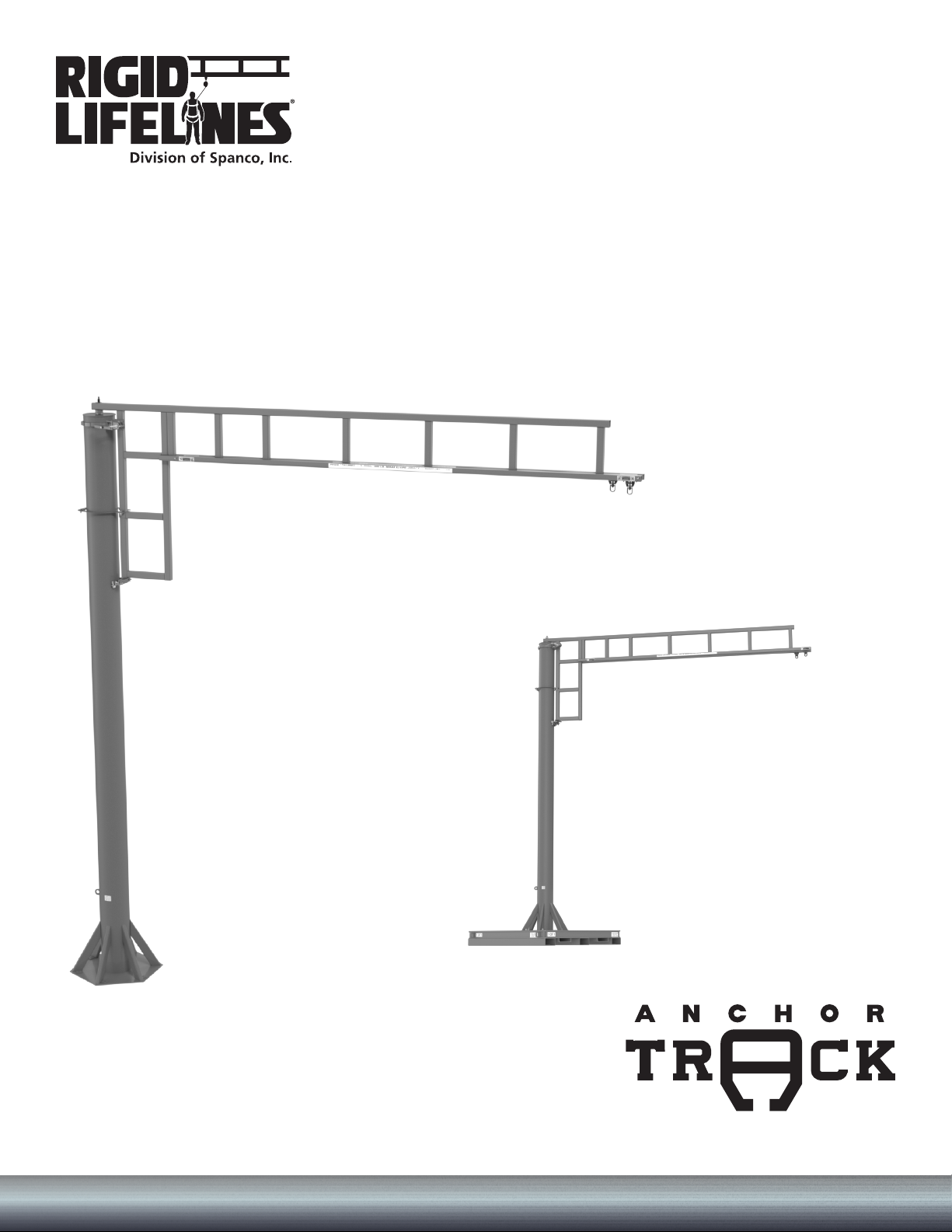
FREESTANDING SWING ARM
ANCHOR TRACK™ SYSTEM
Assembly and Operation Instruction Manual
Freestanding Swing Arm
Portable Base Swing Arm
ISO 9001:2015 Registered
Manual 103-0070 Effective Date: March 2021

i Rigid Lifelines®Freestanding Swing Arm AnchorTrack™System | 1-800-869-2080 1-800-869-2080 | Rigid Lifelines®Freestanding Swing Arm Anchor Track™System ii
RIGID LIFELINES CONDITIONS OF USE AND WARNING STATEMENT
1. Read, understand, and follow the manual, assembly drawings, and warnings provided with your system
before beginning installation.
2. This manual, and any other instructions, must be provided to the users of this equipment. The user must
understand the equipment’s proper use and limitations.
3. A fall event can result in serious injury or death. This equipment, when used properly, reduces the chances of
those outcomes.
4. Always perform a hazard analysis before use that will identify impact hazards, swing hazards, or any other
hazards that may exist. Address and correct all hazards before use.
5. Always have a written rescue plan that defines who will rescue a fallen worker, what equipment will be used,
and optimum rescue response time. If the same system will be used for rescue, a minimum of a two-man
system must be specified.
6. Follow all current requirements of ANSI Z359 (or CSA Z259 in Canada).
7. Each component and system must be employed and maintained in accordance with all OSHA and ANSI standards.
8. Per OSHA and ANSI (or CSA Z259 in Canada) requirements, designate a competent person who can fulfill
obligations of all regulations.
9. Note the maximum number of users and weight capacities are listed on a label on the system. Exceeding the
capacities listed on this label can result in serious injury or death.
10. Always check for overhead hazards, such as power lines, trees, overhead structures, or walls, before using or
moving system.
11. Any component replacement, addition, or change to any portion of the system must be evaluated by a
Qualified Person as defined by OSHA standards.
12. Never use this system for material handling.
13. Never use the system with scaffolding.
14. Never use the system alone without a monitor. Use the buddy system when using fall protection. The monitor,
or “buddy,” does not need to be attached to the system, but just nearby supervising.
15. Consult with a qualified person for minimum fitness requirements for workers. Determination of minimum
fitness levels of workers prior to use of system is by others.
16. For mobile systems—It is the responsibility of the user and their management’s Competent Person to
determine that the system’s base is level, the masts are plumb, and that the entire, leveled system is stable
before every use.
17. For movable track systems—Always use the system in work spaces that allow you to move the system’s
runway as close as possible to the center of the work area.
18. Before each use, inspect the system for bent, broken, cracked, or missing components.
19. A competent person must thoroughly inspect the system annually and after each fall event.
20. There should never be any type of loading past the end stops for any reason.
21. When connecting track sections on runway systems, track splice and truss splice plates are required. For
trussed track, splice joint centers must be within maximum 48 inches of the hanger support centers unless
otherwise specified. For plain track, splice track centers must be within maximum18 inches of the hanger
support centers unless otherwise specified.
22. Systems with flush clamp hangers do not require sway bracing. However, all systems mounted to the ceiling
must be laterally and longitudinally braced with bracing provided by others.

i Rigid Lifelines®Freestanding Swing Arm AnchorTrack™System | 1-800-869-2080 1-800-869-2080 | Rigid Lifelines®Freestanding Swing Arm Anchor Track™System ii
23. If supplied, all drive systems are chain driven, and as a result, will experience some backlash in the drive
assembly. Although backlash cannot be fully eliminated, it can be reduced by tightening the drive chain.
Torque limiters, if supplied, require special attention. Most drive issues result from improper torque limiter
adjustment or installation.
24. It is the customer’s responsibility to confirm that the system and components will work in and are acceptable
for their specific application and environment.
25. For foundation-mounted systems, bracing is not required for non-seismic applications. However, if any sway
is perceived as undesirable, lateral bracing can be installed to the system by others. To achieve desired rigidity
for a specific application, Rigid Lifelines®recommends consulting a professional engineer in your area to
satisfy all codes and ordinances. For foundation-mounted systems, chemical anchor bolts supplied by others
are required and must provide approximately 7000-pound pull-out force. More accurate pull-out forces are
available upon request.
26. Engineering of any attachment points must be done by others.
27. Component appearances and dimensions shown are approximate and subject to change without notice. All
catalog dimensions are developed using standard components for the spans and capacities. Substitution of
optional trolleys or other components will affect certain dimensions.
28. All Rigid Lifelines Anchor Track™Systems meet or exceed OSHA and ANSI requirements.
29. Never load the track at an angle greater than specified in the system’s user manual.
30. Never use the system with the attachment point below the D-Ring of the harness.
31. Only the following self-retracting lanyard (SRL) design specifications are acceptable for use on Rigid Lifelines
Anchor Track Systems:
a ) 900-pound maximum average arresting force (MAAF)
b ) 4.5 feet-per-second lock up speed
c ) Disk or drum braking mechanism
d ) Wire rope SRL’s can be used for indoor or outdoor applications
e ) Fabric or web SRL’s can be used only for indoor applications
32. The following energy-absorbing lanyards are not acceptable: rip-stitch packs, shock packs, or stretchable
energy.
33. Choose the shortest length SRL that will allow the workers to perform their job function. The shortest length
SRL will reduce total fall distance by reducing “cable cinching” on the internal SRL pulley. Fabric lanyards
stretch under load. The longer the lanyard, the longer the stretch.
34. Never use metallic cables or metallic SRL’s around electrical power sources.
35. Only an ANSI (or CSA in Canada) full-body harness is acceptable for use on Rigid Lifelines Anchor Track
Systems.
36. Never use body belts on this system.
37. Never add additional carabiners, D-Rings, shackles, or connecting hardware to this system.
38. On Traveling Bridge Anchor Track Systems, always position the bridge(s) directly overhead of worker(s) at all
times.
39. If a boom is provided, never apply a lateral load at the boom tip.
40. Never deviate from the above unless you have written permission and authorization from Rigid Lifelines.
RIGID LIFELINES CONDITIONS OF USE AND WARNING STATEMENT

iii Rigid Lifelines®Freestanding Swing Arm AnchorTrack™System | 1-800-869-2080 1-800-869-2080 | Rigid Lifelines®Freestanding Swing Arm Anchor Track™System 1
Follow the Inspection Checklists in this manual: review the
first checklist before each use and the second checklist for
after a fall event and annual inspections.
NEVER EXCEED 30 DEGREES OFF-PLUMB (OFF-CENTER)
LOADING.
Portable Base Swing Arm Only
Do not move the system while workers are still connected
to it; doing so may result in serious injury or death.
Do not use the system on an incline; only use the system
on surfaces that are firm and level. NEVER place the system
near a ledge.
Before moving system, ensure that the system capacity
doesn’t exceed the forklift capacity.
Portable Base Swing Arm Only (Continued)
Before moving system, use the boom lock to secure the
track arm weldment to keep it from rotating.
Forks must be 72 inches or longer to move the system.
NEVER exceed five miles per hour while moving.
When moving the system, the upper portable base must
remain bolted to the mast and track arm weldment. If your
system requires stacked portable bases, the lower bases
may be unbolted and moved separately.
Only use portable base(s) on 3,000 PSI or greater
concrete. Before using portable base(s) on macadam
surfaces, contact a Technical Sales Support Specialist at
800-869-2080.
This system must be used with an ANSI-rated self-retracting lanyard (SRL).
If the system is used outdoors, it is highly recommended that a steel cable SRL with
heavy-duty housing be used for improved durability against UV radiation and moisture.
A web strap ANSI-rated SRL may be acceptable for use as long as a Competent Person has
evaluated the situation and determined that there are no factors present that can have an
immediate negative impact on the integrity of the SRL’s webbing material AND that the
Competent Person inspects the condition of the SRL’s webbing and housing prior to each use.
Completely retracting the SRL after each use (e.g., using a
retrieval tagline) is essential: otherwise, the SRL’s internal
spring remains under tension, and it quickly loses its ability
to arrest a freefall properly.
Retrieval taglines must never be used as an anchorage;
doing so could result in serious injury or death.

iii Rigid Lifelines®Freestanding Swing Arm AnchorTrack™System | 1-800-869-2080 1-800-869-2080 | Rigid Lifelines®Freestanding Swing Arm Anchor Track™System 1
TABLE OF CONTENTS
CONDITIONS OF USE AND WARNINGS STATEMENT ................................................................................i-iii
SYSTEM APPLICATIONS ................................................................................................................................... 2
STANDARDS AND COMPLIANCE.................................................................................................................... 2
REQUIRED TRAINING........................................................................................................................................ 2
ASSEMBLY INSTRUCTIONS .............................................................................................................................. 3
1. Equipment Needed for Assembly ................................................................................................................................3
2. Inventory ....................................................................................................................................................................3
3. Attaching the Mast Assembly to the Concrete Foundation ..........................................................................................4
4. Portable Base Only: Attaching the Mast Assembly to the Foundation ...................................................................... 5-6
5. Attaching the Track Arm Weldment to the Mast .........................................................................................................6
6. Attaching the Pivot Ring to the Mast and Track Arm Weldment ..................................................................................7
7. Final Assembly ........................................................................................................................................................ 7-8
Intermediate Bumper Installation (if Supplied)..................................................................................................................9
CORRECT SYSTEM USAGE AND OPERATION .................................................................................10-11
MAINTENANCE................................................................................................................................................ 11
LABELING ......................................................................................................................................................... 12
FREESTANDING SWING ARM INSPECTION CHECKLISTS .......................................................................... 13
Freestanding Swing Arm Anchor Track™ System............................................................................................................ 13
Annual Anchor Track™System ...................................................................................................................................... 14
PRODUCT WARRANTY COVERAGE............................................................................................................... 15
ABOUT RIGID LIFELINES®............................................................................................................. BACK COVER
Table of contents
Popular Automobile Accessories manuals by other brands


ULTIMATE SPEED
ULTIMATE SPEED 279746 Assembly and Safety Advice

SSV Works
SSV Works DF-F65 manual

ULTIMATE SPEED
ULTIMATE SPEED CARBON Assembly and Safety Advice

Witter
Witter F174 Fitting instructions

WeatherTech
WeatherTech No-Drill installation instructions

TAUBENREUTHER
TAUBENREUTHER 1-336050 Installation instruction