Calpeda NMP User manual

Pompe autoadescanti per piscine con prefiltro incorporato
Self-priming swimming pool pumps with built-in strainer basket
Selbstansaugende Schwimmbadpumpen mit eingebautem Vorfilter
Pompes autoamorçantes pour piscines avec préfiltre incorporé
Bombas autoaspirantes para piscinas con prefiltro incorporado
Själv-evakuerande poolpumpar med inbyggd silkorg
Zelfaanzuigende zwembadpompen met ingebouwd voorfilter
Αντλίες αυτόματης αναρρόφησης για πισίνες με ενσωματωμένο προφίλτρο
Самозаливающиеся насосы для бассейнов со встроенным предварительным фильтром
带内置过滤器的自吸泳池泵
N P
ISTRUZIONI ORIGINALI PER L’USO Pagina 2 taliano
OPERATING INSTRUCTIONS Page 6 English
BETRIEBSANLEITUNG Seite 10 Deutsch
INSTRUCTIONS POUR L’UTILISATION
Page 14 Français
INSTRUCCIONES DE USO Página 18 Español
DRIFT/INSTALLATIONSANVISNINGAR
Sidan 22 Svenska
BEDIENINGSVOORSCHRIFT Pagina 26 Nederlands
ΟΔΗΓΙΕΣ ΧΕΙΡΙΣΜΟΥ Σελίδα 30 Ελληνικά
àÌÒÚÛ͈ËË ÔÓ ˝ÍÒÔÎÛ‡Ú‡ˆËË ëÚ. 34 êÛÒÒÍËÈ
安装使用手册 页码 38 中文
ST NMP 06_2016_MXS 11_03con gall 03/06/16 08:53 Pagina 1

THIS INSTRUCTION MANUAL IS THE PROPERTY OF
CALPEDA S.P.A. ANY REPRODUCTION, EVEN IF PAR-
TIAL, IS FORBIDDEN
SU ARY
1 General information . . . . . . . . . . . . . . . . . . . . . . . . . . 6
2 TECHN CAL DESCR PT ON . . . . . . . . . . . . . . . . . . . 6
3 TECHN CAL FEATURES. . . . . . . . . . . . . . . . . . . . . . 7
4 SAFETY . . . . . . . . . . . . . . . . . . . . . . . . . . . . . . . . . . . 7
5. TRANSPORTAT ON AND HANDL NG . . . . . . . . . . . 7
6. NSTALLAT ON . . . . . . . . . . . . . . . . . . . . . . . . . . . . . 7
7. START-UP AND OPERAT ON. . . . . . . . . . . . . . . . . . 8
8 MA NTENANCE . . . . . . . . . . . . . . . . . . . . . . . . . . . . . 8
9 D SPOSAL . . . . . . . . . . . . . . . . . . . . . . . . . . . . . . . . . 9
10 SPARE PARTS . . . . . . . . . . . . . . . . . . . . . . . . . . . . . 9
11 TROUBLESHOOT NG . . . . . . . . . . . . . . . . . . . . . . . . 9
12 ANNEXES . . . . . . . . . . . . . . . . . . . . . . . . . . . . . . . . 42
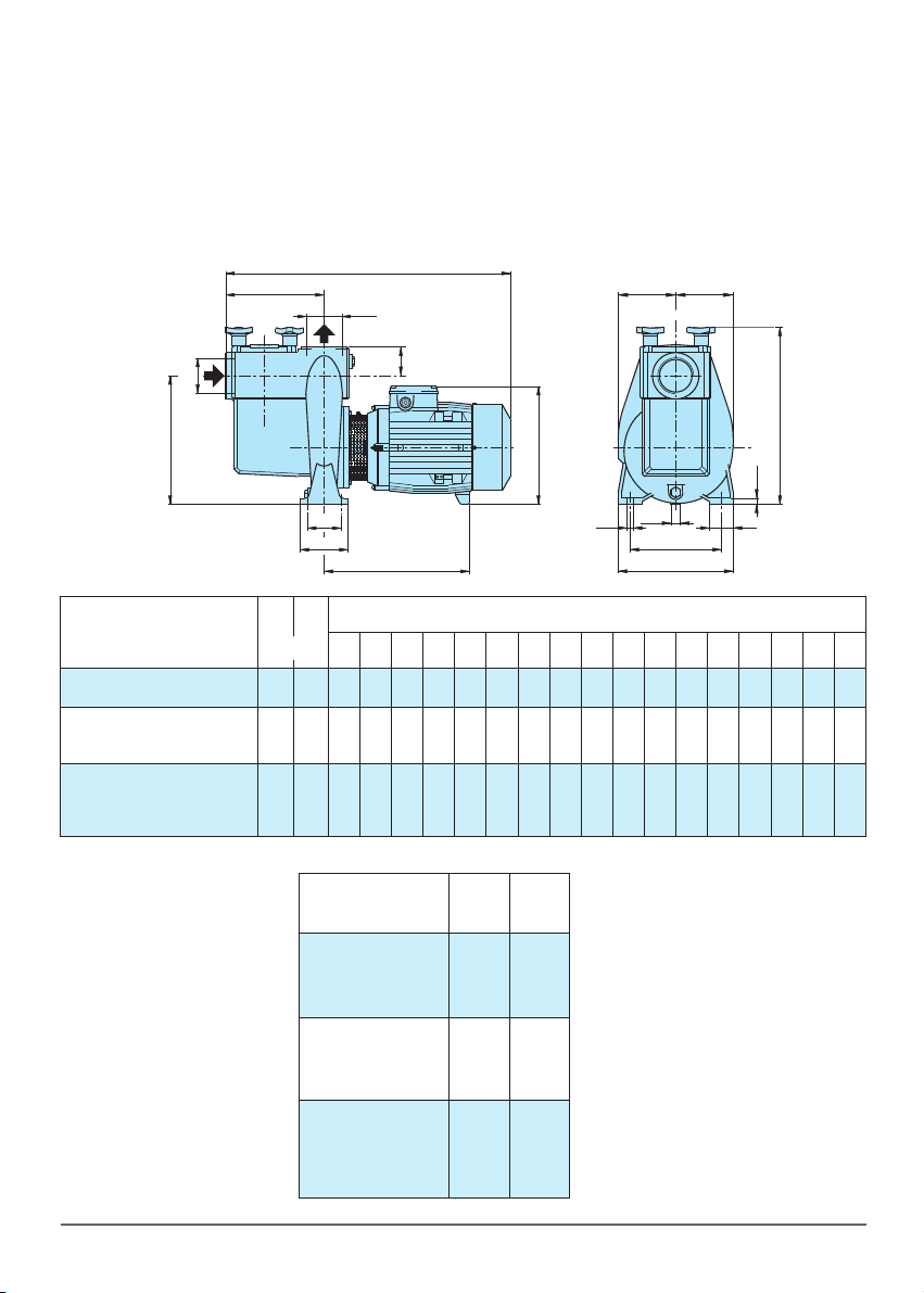
12.1 Dimensions and weights . . . . . . . . . . . . . . . . . . . . . 42
12.2 nstallation examples . . . . . . . . . . . . . . . . . . . . . . . . 43
12.3 Designation of parts . . . . . . . . . . . . . . . . . . . . . . . . . 44
12.4 Section . . . . . . . . . . . . . . . . . . . . . . . . . . . . . . . . . . . 46
Copy of the declaration of conformity . . . . . . . . . . . . . . . . 47
1 GENERAL INFOR ATION
Before using the product carefully read the information con-
tained in this instruction manual, the manual should be kept
for future reference.
talian is the original language of this instruction manual, this
language is the reference language in case of discrepancies
in the translations.
This manual is part of the essential safety requirement and
must be retained until the product is finally de-commissioned.
The customer, in case of loss, can request a copy of the
manual by contacting Calpeda S.p.A. or their agent, spe-
cifying the type of product data shown on the label of the
machine (see 2.3 Marking)
Any changes, alterations or modifications made to the pro-
duct or part of it, not authorized by the manufacturer, will
revoke the "CE declaration" and warranty.
This appliance should not be operated
by children younger than 8 years,
people with reduced physical, sensory
or mental capacities, or inexperienced
people who are not familiar with the
product, unless they are given close
supervision or instructions on how to
use it safely and are made aware by a
responsible person of the dangers its
use might entail.
Children must not play with the
appliance.
t is the user's responsibility to clean
and maintain the appliance. Children
should never clean or maintain it
unless they are given supervision.
Do not use in ponds, tanks or
swimming pools or where people may
enter or come into contact with the
water.
Read carefully the installation section
which sets forth:
- The maximum permissible structural
working pressure (chapter 3.1).
- The type and section of the power
cable (chapter 6.5).
- The type of electrical protection to be
installed (chapter 6.5).
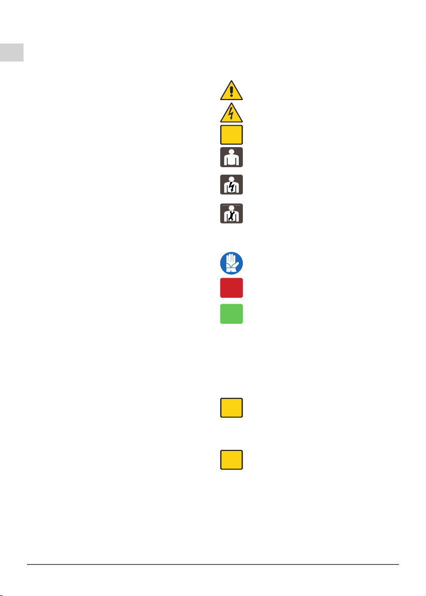
1.1 Symbols
To improve the understanding of the manual, below are indica-
ted the symbols used with the related meaning.
nformation and warnings that must be observed,
otherwise there is a risk that the machine could damage
or compromise personnel safety.
The failure to observe electrical information and
warnings, could damage the machine or compromise
personnel safety.
Notes and warnings for the correct management of
the machine and its parts.
Operations that could be performed by the final user.
After carefully reading of the instructions, is responsible
for maintenance under normal conditions. They are
authorized to affect standard maintenance operations.
Operations that must be performed by a qualified
electrician. Specialized technician authorised to affect all
electrical operations including maintenance. They are
able to operate with in the presence of high voltages.
Operations that must be done performed by a qualified
technician. Specialized technician able to install the
device, under normal conditions, working during
"maintenance", and allowed to do electrical and
mechanical interventions for maintenance. They must be
capable of executing simple electrical and mechanical
operations related to the maintenance of the device.
ndicates that it is mandatory to use individual
protection devices.
Operations that must be done with the device
switched off and disconnected from the power supply.
Operations that must be done with the device
switched on.
1.2 anufacturer name and address
Manufacturer name: Calpeda S.p.A.
Address: Via Roggia di Mezzo, 39
36050 Montorso Vicentino - Vicenza / talia
www.calpeda.it
1.3 Authorized operators
The product is intended for use by expert operators divided
into end users and specialized technicians. (see the symbols
above).
t's forbidden, for the end user, carry out operations
which must be done only by specialized technicians.
The manufacturer declines any liability for damage
related to the non-compliance of this warning.
1.4 Warranty
For the product warranty refer to the general terms and con-
ditions of sale.
The warranty covers only the replacement and the
repair of the defective parts of the goods (recognized
by the manufacturer).
The Warranty will not be considered in the following cases:
- Whenever the use of the device does not conform to the
instructions and information described in this manual.
- n case of changes or variations made without authorization
of the manufacturer.
- n case of technical interventions executed by a non-authori-
zed personnel.
- n case of failing to carry out adequate maintenance.
1.5 Technical assistance
Any further information about the documentation, technical
assistance and spare parts, shall be requested from: Calpeda
S.p.A. (paragraph 1.2).
i
OFF
ON
i
i
GB
NMP Rev. 15 - Operating nstructionsPagina 6 / 48
ST NMP 06_2016_MXS 11_03con gall 03/06/16 08:53 Pagina 6

2 TECHNICAL DESCRIPTION
Close-coupled self-priming centrifugal pumps with built-in strainer.
nner basket with Ø 3 mm holes.
NMP: version with pump casing and lanter bracket in cast iron.
B-NMP: version with pump casing and lanter bracket in bronze.
(the pumps are supplied fully painted).
2.1 Intended use
For water circulation in swimming pool filtration systems.
For clean or slightly dirty water with solids in suspension.
Liquid temperature up to 60° C.
2.2 Improper use
The device is designed and built only for the purpose descri-
bed in paragraph 2.1.
mproper use of the device is forbidden, as is use
under conditions other than those indicated in these
instructions.
mproper use of the product reduces the safety and the effi-
ciency of the device, Calpeda shall not be responsible for fai-
lure or accident due to improper use.
2.3 arking
The following picture is a copy of the name-plate that is on
the external case of the pump.
3 TECHNICAL FEATURES
3.1 Technical data
Dimensions and weight (paragraph 12.1).
Nominal speed 2900/3450 rpm
Protection P54
Supply voltage / Frequency
230 delta/400 star V3 ~ 50Hz
220 delta/380 star V3 ~ 60Hz
Sound pressure at minimum immersion depth:
up to 2,2 kW: ≤ 70 dB (A);
from 3 to 11 kW: ≤ 85 dB (A).
Max. starts per hour at regular intervals: 60 up to
2,2 kW
40 from 3 to
7,5 kW
20 from 9,2 to
11 kW
Maximum permissible working pressure up to 60 m (6 bar).
3.2 Operating conditions
nstallation in well ventilated location protected from the
weather, with a maximum ambient temperature of 40 °C.
4 SAFETY
4.1 General provisions
Before using the product it is necessary to know all
the safety indications.
Carefully read all operating instructions and the
indications defined for the different steps: from
transportation to disposal.
The specialized technicians must carefully comply
with all applicable standards and laws, including local
regulations of the country where the pump is sold.
The device has been built in conformity with the
current safety laws. The improper use could damage
people, animals and objects.
The manufacturer declines any liability in the event of
damage due to improper use or use under conditions
other than those indicated on the name-plate and in
these instructions.
Follow the routine maintenance schedules and the
promptly replace damaged parts, this will allows the
device to work in the best conditions.
Use only original spare parts provided from Calpeda
S.p.A or from an authorized distributor.
Don't remove or change the labels placed on the
device.
Do not start the device in case of defects or damaged parts
.
Maintenance operations, requiring full or partial
disassembly of the device, must be done only after
disconnection from the supply.
4.2 Safety devices
The device has an external case that prevents any contact
with internal parts.
4.3 Residual risks
The appliance, designed for use, when used in-line with the
design and safety rules, doesn't have residual risks.
4.4 Information and Safety signals
For this kind of product there will not be any signals on the
product.
4.5 Individual protection devices
During installation, starting and maintenance it is suggested to
the authorized operators to consider the use of individual
protection devices suitable for described activities.
During ordinary and extraordinary maintenance interventions,
where it is required to remove the filter, safety gloves are
required.
Signal individual protection device
HAND PROTECT ON
(gloves for protection against chemical, thermal and
mechanical risks).
5. TRANSPORTATION AND HANDLING
The product is packed to maintain the content intact.
During transportation avoid to stack excessive weights.
Ensure that during the transportation the packed cannot
move.
The transport vehicles must comply, for the weight and
dimensions, with the chosen product (see paragraph 12.1
dimensions and weights).
5.1 Handling
Handle with care, the packages must not receive impacts.
Avoid to impact onto the package materials that could dama-
ge the pump.
f the weight exceeds 25 Kg the package must be handled by
two person at the same time (see paragraph 12.1 dimensions
and weights).
6 INSTALLATION
6.1 Dimensions
For the dimensions of the device refer to the annex
"Dimensions" (paragraph 12.1 Annexes).
6.2 Ambient requirements and installation site dimen-
sions
The customer has to prepare the installation site in order to
guarantee the right installation and in order to fulfill the device
requirements (electrical supply, etc...).
The place where the device will be installed must fulfill the
requirements in the paragraph 3.2.
t's Absolutely forbidden to install the machine in an
environment with potentially explosive atmosphere.
6.3 Unpacking
nspect the device in order to check any damages
which may have occurred during transportation.
Package material, once removed, must be discarded/recy-
cled according to local laws of the destination country.
Raise the pump-motor unit slowly (see paragraph 12.2 fig.1),
i
i
GB
NMP Rev. 15 - Operating nstructions Pagina 7 / 48
Made in Italy
MONTORSO
XXXXXXX
Q min/max X/X m3/h
XXXXXXX
H max/min X/X m IP XX
n XXXX/min
220∆/380Y V3~50Hz cosø X
X/X A
XXXXXXXX
S1 l.cl. XXkg
XkW (XHp) S.F.
VICENZA
1
2
3
4
5
6
7
8910
16
15
14
13
12
11
1 Pump type
2 Delivery
3 Head
4 Rated power
5 Tension nominale
6 Nom. motor current
7 Notes
8 Fréquence
9 Operation Duty
10 nsulation class
11 Weight
12 Power factor
13 Rotation speed rpm
14 Protection
15 Serial number
16 Certifications
ST NMP 06_2016_MXS 11_03con gall 03/06/16 08:53 Pagina 7

Pagina 8 / 48 NMP Rev. 15 - Operating nstructions
GB
making sure it does not move from side to side in an uncon-
trolled way, to avoid the risk of imbalance and tipping up.
6.4. Installation
The N P pumps must be installed with the rotor axis horizontal
and delivery port upwards.
Place the pump as close as possible to the suction source.
Provide clearance around the unit for motor ventilation, for
easier inspection and maintenance.
6.4.1. Pipes
Ensure the insides of pipes are clean and unobstructed befo-
re connection.
ATTENTION: The pipes connected to the pump should be
secured to rest clamps so that they do not transmit
stress, strain or vibrations to the pump.
The inside diameter of the pipe-work depends on the desired
flow.
Provide a diameter assuring a liquid flow not greater than 1.5
m/s for suction and 3 m/s for delivery.
The pipe diameters must never be smaller than the pump
connection ports.
6.4.2. Suction pipe
The suction pipe must be perfectly airtight and be led
upwards in order to avoid air pockets.
f operating with flexible hoses, use a reinforced spiral suc-
tion hose in order to avoid hose narrowing due to a suction
vacuum.
With a pump located above the water level (suction lift ope-
ration), fit a foot valve or a check valve on the suction con-
nection.
With a pump located below water level (inflow under positi-
ve suction head) install a gate valve.
6.4.3. Delivery pipe
Fit a gate valve in the delivery pipe to adjust delivery, head,
and absorbed power.
nstall a pressure gauge.
With a geodetic head of over 15 m fit a check valve between
the pump and the gate valve in order to protect the pump
from water hammering.
6.5 Electrical connection
Electrical connection must be carried out only by a
qualified electrician in accordance with local
regulations.
Follow all safety standards.
The unit must be properly earthed (grounded).
Connect the earthing (grounding) conductor to the terminal
with the marking.
Compare the frequency and mains voltage with the name-
plate data and connect the supply conductors to the terminals
in accordance with the appropriate diagram inside the termi-
nal box cover.
ATTENTION: never allow washers or other metal
parts to fall into the internal cable opening between
the terminal box and stator. f this occurs, dismantle
the motor to recover the object which has fallen inside.
f the terminal box is provided with an inlet gland, use a flexi-
ble power supply cord of the H07 RN-F type with section of
cable not less than 11 TAB EC 60335-1.
f the terminal box is provided with an inlet bushing, connect
the power supply cord through a conduit.
For use in swimming pools (not when persons are in the
pool), garden ponds and similar places, a residual current
device with ΔN not exceeding 30 mA must be installed in
the supply circuit.
nstall a device for disconnection from the mains (switch)
with a contact separation of at least 3 mm in all poles.
With a three-phase motor install an overload protection with
curve D device appropriate for the rated current of the pump.
Single-phase
N P ,
are supplied with a capacitor connec-
ted to the terminals and (for 220-240 V - 50 Hz) with an incor-
porated thermal pro
tector.
7 STARTUP AND OPERATION
7.1 Preliminary checks before start-up of the pump
Do not start-up the device in case of damaged parts.
7.2 First starting
ATTENTION: never run the pump dry. Start the pump after fil-
ling it completely with liquid.
When the pump is located above the water level (suction
lift operation) fill the pump with water up to suction pipe level
through the opening on the strainer after removing the cover
(fig. 2).
ATTENTION: for transportation the cover is temporarily
closed with hexagon nuts.
Replace them with the hand knobs (15.12) located inside
the filter.
When operating with the pump below water level (inflow
under positive suction head), fill the pump by opening the
suction gate valve slowly and completely, keeping the deli-
very gate valve open to release the air.
With a three-phase motor check that the direction of rota-
tion is as shown by the arrow on the pump casing, otherwise,
disconnect electrical power and reverse the connections of
two phases.
With a suction lift operation it may be necessary to wait a few
minutes for the pump to prime.
Check that the pump works within its field of performance,
and that the absorbed current shown on the name-plate is not
exceeded.
Otherwise adjust the delivery gate valve.
7.3 Switch off of the pump
The appliance must be switch off every time there are
faults. (see troubleshooting).
The product is designed for a continuous duty, the switch off
is performed by disconnecting the power supply by means
the expected disconnecting devices. (see paragraph "6.5
Electrical connection").
8 AINTENANCE
Before any operations it's necessary to disconnect the power
supply.
f required ask to an electrician or to an expert technician.
Every maintenance operations, cleaning or reparation
executed with the electrical system under voltage, it
could cause serious injuries to people.
n case of extraordinary maintenance, or maintenance opera-
tions that require part-removing, the operator must be a quali-
fied technician able to read schemes and drawings.
t is suggest to register all maintenance operation executed.
During maintenance keep particular attention in order
to avoid the introduction of small external parts, that
could compromise the device safety.
t is forbidden to execute any operations with the
direct use of hands. Use water-resistant, anti-cut
gloves to disassemble and clean the filter or in other
particular cases.
During maintenance operations external personnel is
not allowed.
Maintenance operations that are not described in this manual
must be made only by special personnel authorized by
Calpeda S.p.A.
For further technical information regarding the use or the
maintenance of the device, contact Calpeda S.p.A.
OFF
OFF
ON
i
i
ST NMP 06_2016_MXS 11_03con gall 03/06/16 08:53 Pagina 8

8.1 Routine maintenance
Before every maintenance operations disconnect the
power supply and make sure that the device could not
accidentally operate.
Inspect and clean the strainer basket periodically.
The strainer can be easily accessed by removing the strainer
cover. With the pump located below water level, close the suc-
tion and delivery gate valves before removing the cover.
Disinfectant or chemical products for water
treatment must not be poured directly into the
pump.
Risk of reactions and emission of harmful fumes.
Risk of corrosion in stagnant water conditions (also with an
increase in temperature and decrease of pH value).
When the pump remains inactive it must be emptied com-
pletely if there is a risk of freezing (
see paragraph 12.2
fig.
3).
Before restarting the unit, check that the shaft is not jammed
and fill the pump casing completely with liquid.
8.2 Dismantling the system
Close the suction and delivery gate valves and drain the pump
casing before dismantling the pump.
8.3. Dismantling the pump
Close the suction and delivery gate valves and drain the pump
casing before dismantling the pump.
For dismantling and reassembly see construction in the cross
section drawing.
The motor and all internal parts can be dismantled without remo-
ving the pump casing and pipes.
By removing the nuts (14.28) the motor can be taken out com-
plete with the impeller.
9. DISPOSAL
The final disposal of the device must be done by specialized
company.
Make sure the specialized company follows the classification
of the material parts for the separation.
Observe the local regulations and dispose the device accor-
dingly with the international rules for environment protection.
10 SPARE PARTS
10.1 Spare-parts request
When ordering spare parts, please quote their designation,
position number in the cross section drawing and rated data
from the pump name plate (type, date and serial number).
The spare parts request shall be sent to CALPEDA S.p.A. by
phone, fax, e-mail.
Changes reserved.
OFF
OFF
OFF
GB
NMP Rev. 15 - Operating nstructions Pagina 9 / 48
11. Troubleshooting
WARNING: Turn off the power supply before performing any operations.
Do not allow the pump or motor to run when dry even for a short period
Strictly follow the user instructions and if necessary contact an authorised service centre
OFF
PROBLE
1) The engine does
not start
2) Pump blocked
3)The pump func-
tions but no water
comes out
4) nsufficient flow
5)
Noise and vibrations
from the pump
6) Leakage from the
mechanical seal
PROBABLE CAUSES
1a) Unsuitable power supply
1b) ncorrect electrical connections
1c) Engine overload protective device cuts in.
1d) Blown or defective fuses
1e) Shaft blocked
1f) Motor failed
2a) Prolonged periods of inactivity .
2b) Presence of solid bodies in the impeller
2c) Bearings blocked
3a) Presence of air inside the pump or suction pipe
3b) Possible infiltration of air.
3c) Foot valve blocked or suction pipe not fully
immersed in liquid
3d) Suction filter blocked
4a) Pipes and accessories with diameter too small
4b) Presence of deposits or solid bodies in the
impeller
4c) Rotor deteriorated
4d) Worn rotor and pump case
4e) Gases dissolved in the water
4f) Excessive viscosity of the liquid pumped
4g) ncorrect direction of rotation
5a) Worn bearings
5b) Unbalanced power supply
6a) The mechanical seal has functioned when dry or
has stuck
6b) Mechanical seal scored by presence of abrasive
parts in the liquid pumped
6c) Mechanical seal unsuitable for the type of
application
6d) Slight initial drip during filling or on first start-up
POSSIBLE RE EDIES
1a) Check that the mains frequency and voltage are suitable.
1b) Connect the power supply cable correctly. Check the setting of the
thermal overload protection.
1c) Check the power supply and make sure that the pump shaft is
turning freely. Check the setting of the thermal overload protection.
1d) Replace the fuses, check points a) and c)
1e)
See “Blocked pump” instruction booklet
1f) Repair or replace the engine.
2a) Unblock the pump by using a screw driver to turn the relevant notch
on the back of the shaft.
2b) Remove any solid foreign bodies inside the impeller
2c) Replace the bearings.
3a) Release the air from the pump using the delivery control valve.
3b) Check which part is not tight and seal the connection.
3c) Clean or replace the bottom valve and use a suitable suction pipe .
3d) Clean the filter, if necessary, replace it . See point 2b) also.
4a) Use pipes and accessories suitable for the specific application
4b) Clean the impeller and install a suction filter
4c) Replace the impeller
4d) Replace the impeller and the pump casing
4e) Perform the opening and closing manoeuvres through the feeder
gate
4f) The pump is unsuitable
4g) nvert the electrical connections in the terminal board
5a) Replace the bearings
5b) Check that the mains voltage is right
n cases 6a), 6b) and 6c), replace the seal
6a) Make sure that the pump casing is full of liquid and that all the air has
been expelled.
6b) nstall a suction filter and use a seal suited to the characteristics of
the liquid being pumped.
6c) Choose a seal with characteristics suitable for the specific application
6d) Wait for the seal to adjust to the rotation of the shaft. f the problem
persists, see points 6a), 6b) or 6c).
ST NMP 06_2016_MXS 11_03con gall 03/06/16 08:53 Pagina 9

页码 38 / 48 NMP Rev. 15 - 安装使用手册
中文
本操作手册属
CALPEDA S.P.A.
所有,禁止任何形式的复制,
即使是部分的。
摘要
1总则........................................................................... 38
2 技术说明 ................................................................... 39
3 技术特性 ................................................................... 39
4 安全性 ....................................................................... 39
5. 搬运操作 ................................................................... 39
6. 安装........................................................................... 39
7. 启动和运行................................................................ 40
8 维修........................................................................... 40
9 处理........................................................................... 41
10 备件........................................................................... 41
11 故障诊断 ................................................................... 41
12 附件........................................................................... 42
12.1 尺寸与重量................................................................ 42
12.2 安装示例 ................................................................... 43
12.3 部件名称 ................................................................... 44
12.4 剖面图 ........................................................................46
一致性声明.......................................................................... 47
1 总则
使用本产品前请仔细阅读此操作手册的内容,并保留此操作手
册以供参考。
此操作手册为意大利语,如有翻译偏差以意大利语为准。
此操作手册是安全保障必不可少的一部分,在产品最终达到正
常工作前请牢记本手册。
万一用户不慎遗失本手册,可以向CALPEDA S.P.A.或其代理
商要求一份复印件,请详述产品铭牌上的资料(见2.3 标记)
未经制造商认可的有关其产品或部件的任何更改变化,将撤消
“CE 声明”和质保。
此产品不应让8岁以下的未成年、
身体有缺陷、心智不全或无任何
经验的人操作,除非在充分的指
导或监督下让相关人员知道如何
安全的使用,并且通过一个负责
人来让相关人员了解到可能会产
生的危险。
不得让儿童接触本产品。
用户有义务清洁和维护本产品。
除非在有人监督的情况下,否则
儿童不应清洁和维护本产品。
不要使用在池塘、水箱或泳池等人
为可以进入或接触的水环境中。
仔细阅读安装部分的规定:
-最大允许的结构工作压力详见3.1
-电源线的类型及剖面详见6.5
-所安装电器设备的防护类型详见
6.5
1.1 符号标记
为了便于理解本操作手册,下面给出常用标记符号的含义。
一定要注意通告和警告的标记,否则可能导致产品损
坏或人身安全的风险。
忽略有关电气的警告,可能导致产品损坏或人身安全
的风险
提示和警告正确操作处理产品及其部件
最终用户可以进行的操作
终端用户:仔细阅读本操作手册后,产品使用者可以
负责正常状态下的维护工作。他们可以进行产品的清
洁和长期停滞后的重新启动此类标准维护工作。
必须由有资格的专业电工才能进行的操作
专业电工:有资格的专业电工,负责所有电气设备的
运行包括维护,应具有高压电资格。
必须由有专业技术资格的人才能进行的操作
专业技术人员:正常状态下,具有产品安装和维护能
力的专业技术人员,可以从事电气和机械方面的维护
工作。能够从事简单的与设备维护相关的电气和机械
方面的操作。
指示必须使用个别的保护装置
必须关断电源并断开与电源的连接才能进行的操作
必须接通电源才能进行的操作
1.2 制造商名称和地址
制造商名称:CALPEDA S.P.A.
地址:Via Roggia di Mezzo, 39
36050 Montorso Vicentino - Vicenza / talia
www.calpeda.it
1.3 授权操作者
本产品只能由有经验的终端用户和专业技术人员操作
禁止终端用户操作那些只能由专业技术人员操作的
工作,对未按本规章执行而引起的损害制造商不负
任何责任
1.4 质保
质保参见总则和销售条款
质保期内将更换或维修有问题的产品部件(由制造商
验证的)。
下面因素不在质保范围:
- 由于产品使用者没有按照说明及本手册的通告信息操作造成
的损坏
- 未经制造商认可的对产品的任何改变而造成的损坏
- 由非专业人员操作造成的损坏
- 由不当的维修造成的损坏
1.5 技术支持
任何技术支持、备件及更多的产品信息均可联系:Calpeda
S.p.A. (附件1.2章).
i
i
OFF
ON
i
ST NMP 06_2016_MXS 11_03con gall 03/06/16 08:53 Pagina 38

页码 39 / 48NMP Rev. 15 - 安装使用手册
中文
2 技术说明
带内置过滤器的直联自吸离心泵
内置过滤器篮孔径3mm
NMP:泵壳和笼型支架为铸铁结构
B-NMP:泵壳和笼型支架为青铜结构
(青铜泵壳被喷漆所覆盖).
2.1 预期用途
用于游泳池水的循环过滤
用于清水或有悬浮颗粒的轻度污水
液体温度60℃.
2.2 不当使用
本产品只用于2.1中所述用途
除了本说明手册中指示的用途外,严禁其他不当用途
不当使用将降低本产品的安全性和效率,由于不当使
用而造成的损坏和意外,CALPEDA不承担责任
严禁用于可能有人员进入或与水接触的池塘、水箱
或游泳池
2.3 标记
下面给出的是泵外壳上的标牌的图片
3 技术特性
3.1 技术参数
尺寸和重量(见12.1)
额定转速 2900/3450rpm
保护等级 P54
电压/频率 230角接/400星接 V3” 50Hz
220角接/380 星接 V3” 60Hz
在最小浸入深度下的噪音
up to(不超过) 2,2 kW: ≤ 70 dB (A);
from (从)3 to(至) 11 kW: ≤ 85 dB (A).
定时间间隔下每小时最多启动次数
60 up to(不超过) 2,2 kW
40 from(从) 3 to(至) 7,5 kW
20 from (从)9,2 to(至) 11 kW
最大工作压力为 60 m (6 bar).
3.2 工作条件
请安装在可遮蔽风雨通风良好的场所,最高 环境温度为40℃
4 安全性
4.1 总则
使用本产品前应了解有关安全的指示
仔细阅读所有的操作说明和从搬运到处理的每一步指
示专业技术人员必须认真遵从所有的适用标准和法律
,包括产品应用地当地的规章
产品安装使用应符合现行的安全法规
不当的使用可能会对人身、动物和其他对象造成损害
制造商对由于不当使用或未按本操作手册和标牌的标
示使用所造成的损坏不负责任
按照日程维护计划表操作并及时更换损坏的部件可使
产品工作在最佳状态
使用CALPEDA S.P.A或其指定代理商提供的原厂配
件
不要撕下或改变产品上的标识
当产品有问题或部件有损坏的情况下不要启动产品
由于维修时会全部或部分的拆开产品,因此之前务必断
开供电电源
4.2 安全装置
本产品具有全外部壳体,可防止与内部部件的任何接触
4.3 剩余风险
当按照本产品的设计功能和所有安全规则使用本产品时没有剩
余风险
4.4 通告和安全预示
没有任何安全预示在此类产品上面
4.5 个别的保护装置
在安装、使用和维修期间,建议操作人员使用适合此操作的个
别保护装置或手段
当进行日常或个别的维修工作时,拆过滤器时应带手套
标示的个别保护装置
手的保护
(防热、化学品和机械损害的手套)
5. 搬运操作
货物应包装完好
运输过程中应避免超重,并确保货物不会移动。确保运输车辆
和所运货物尺寸相符合
无需特殊车辆运输
运输车辆应与被运货物的尺寸重量相符合(见 表见12.1 尺寸
与重量)
5.1 搬运
小心搬运,轻拿轻放
避免冲撞包装材料以免损坏泵的外套
对于重量超过25公斤的包装物需由两人同时搬抬(见 表见
12.1 尺寸与重量)
6 安装
6.1 尺寸
产品的尺寸详见附件“尺寸”(附件12.1章)
6.2 环境要求和安装位置的尺寸
客户应将本产品妥当的安装于适当位置以满足设备的要求(供
电需要等)
安装位置应满足章节3.2中的要求
禁止将产品安装于有潜在易燃易爆危险的环境中
i
Made in Italy
MONTORSO
XXXXXXX
Q min/max X/X m3/h
XXXXXXX
H max/min X/X m IP XX
n XXXX/min
220∆/380Y V3~50Hz cosø X
X/X A
XXXXXXXX
S1 l.cl. XXkg
XkW (XHp) S.F.
VICENZA
额定功率
扬程
流量
泵型
转速
保护等级
序列号a
认证
注释
电流
电压 / 相/ 频率
运行工作制 / 绝缘等级 / 重量
功率因数
ST NMP 06_2016_MXS 11_03con gall 03/06/16 08:53 Pagina 39

页码 40 / 48 NMP Rev. 15 - 安装使用手册
中文
6.3 拆箱
开箱检查产品是否因运输而损坏
拆开的包装材料应根据产品使用国当地的法律规定遗弃或再利
用
缓慢提升泵-电机组(见12.2章节 图1)
确保它不会晃来晃去,以避免因不平衡而倾倒.
6.4. 安装
NMP泵安装时应保证转子轴水平出水口向上
尽可能将泵置于靠近水源处
为便于电机的散热,方便检查和维修,应在组件周边留有足够的空
间.
6.4.1 管道
应确保连接前所有管道内部干净、无堵塞;
注意:管道与水泵的连接应当支撑可靠,并紧固联接,以确保不
传递应力应变及振动到泵上章.
管路系统的内径依所需流量而定
管路直径应确保进口流速不超过1.5m/s出口流速不超过3m/s
管路直径不允许小于泵的接口尺寸
6.4.2 进水管
进水管应气密良好并稍向上倾斜以避免窝气
如果连接的是软管,则必须使用内部带有螺旋钢丝的加强型软管
以避免抽吸时将吸入管吸瘪.
当泵置于水面之上时(吸入操作),应在吸入端安装脚阀或单向阀
当泵位于水面之下时(灌入操作)应安装一闸阀
6.4.3. 出水管
在出水管上安装一闸阀以调节出水量、扬程和净功率
安装一压力表
当落差超过15M时应在泵和闸阀之间安装一止回阀以避免水锤
对泵的损害
6.5. 电气联接
必须由合格电工根据当地规范进行电气联接.
必须遵守安全标准.
泵-电机机组必须可靠地接地.
把接地导线接到标有记号的端子上 .
请对照电源电压和铭牌上所标数值,根据接线盒内盖上的电路
图联接电源.
注意: 绝对不允许将垫片等金属部件掉入电机接线盒
的定子线圈中.
如果发生此种问题,必须拆开电机,取出部件。
如果接线盒的进线口为密封管,则应使用H07RN-F型柔软的电
线 电缆的剖面不低于表11 IEC 60335-1的相关规定。
如果接线盒的进线口是套管,则应通过套管连接电线。
作为用于游泳池,花园池塘的泵,必须在电源线路中安装漏电
保护器,其灵敏度不大于30毫安.
安装一个使电源断开的装置,各电极之间至少有3mm的间隙.
对于三相电机,根据其额定电流一定要安装一个过载保护装置
曲线 D.
对于单相的
NN P ,
泵,提供一个连接在接线柱上的电容,对
于220-240V-50Hz的电源,还提供一个相连的热保护装置.
7 启动和运行
7.1 启动前的预检
当存在有故障的部件时不要启动本产品
7.2 首次启动
请注意:千万不要使泵干态运行.
一定先注水后再启动泵.
当泵置于水面之上时(吸入操作)打开泵盖(图2)从过滤器
开口处灌满水直至吸入管处。
注意:因运输原因泵盖由螺母暂时锁闭
可用放置在过滤器里面的手轮替换这些螺母。
当泵位于水面之下工作时(灌入操作),慢慢打开进水闸阀直
到全开以灌满泵,保持出口阀门打开以排气。
对于三相电机应检查其转向是否和泵壳上箭头所示方向一致,
不符,则断开电源互换其中的两相。
对于吸入操作时泵可能需要几分钟时间才能上水正常工作
检查泵是否工作在正常范围,工作电流不应超过铭牌上注明的
电流
否则调整出口阀门
7.3 泵的停车
当存在故障时必须关闭设备
本产品设计为连续工作, 当希望断开本产品时可断开供电电源
停机(见章节6.5 电气连接)
8 维修
任何维修操作前都应该先断开电源,必要时可由电工或专业技术
人员操作
在带电情况下的任何类似清洁或维修的操作都可能对
人身造成严重伤害
突发的维修或需要部分拆解零件的维修,都必须由能看懂结构图
的专业人员来操作
建议记录所有的维修过程,在维修期间特别小心注意不
要带入任何外部细小异物,这会对产品的造成损害
不要在无防护措施的情况下用手直接操作,应带防水
防割的手套进行过滤器的拆解清洁或其他维修工作
维修期间无关人员禁止入内
本操作手册中没有介绍的维修工作只能由CALPEDA授权的特
别人员来完成
有关产品使用和维修的更多信息请联系CALPEDA S.P.A.
8.1 日常维护
每次维修工作前都应先断开电源并确保设备不会意外
接通运转
定期检查并清洁过滤器篮
打开过滤器盖可以很容易的取出过滤器,当泵置于水面之下时,
在打开盖子前应先关闭进出口阀门。
OFF
OFF
ON
i
i
i
OFF
ST NMP 06_2016_MXS 11_03con gall 03/06/16 08:53 Pagina 40

页码 41 / 48NMP Rev. 15 - 安装使用手册
中文
不能将用于处理水质的消毒液或化学品直接倒入泵中
化学反应的危险和有害气体的散发。水在不流动状态下腐蚀的危
险(并且温度会升高和PH值降低)
在泵长期不使用的情况下,如有结冰的可能, 则应彻底排放掉
液体(见12.2章节 图3).
在再次启动泵-电机机组前,一定检查轴是否被卡住,并往泵
内注水.
8.2 系统的分解
分解前,关闭进出口隔栅.
8.3. 泵的拆解
拆解泵之前应关闭进出水口的阀门并排空泵壳内的水。
拆解和组装参见剖面图的结构
在不移动泵壳和管路的情况下即可拆解电机和所有的内部零件。
拧下螺母(14.28)可将完整的电机带着叶轮一起卸下来,.
9. 处理
产品的最终处理应由专业公司操作
确保专业公司是按照材料分类方式处理
按照当地的法规和有关环境保护的国际准则处理
10 备件
10.1 订购备件
订购备件时请根据剖面图提供备件的名称和位置编号及泵铭牌
上的数据(型号、参数和序列号)
备件需求请电话、传真、邮件给CALPEDA S.P.A
保留更改权利
OFF
OFF
11. 常见故障和解决方法
警告:任何操作之前均应断开电源.
决不允许泵组干转,即使是短时间的.
严格按照使用说明书操作,如有必要请联系授权服务中心.
OFF
故障现象
1)电机不转
2)泵卡死不转
3)泵工作但不
出水
4)流量不足
5)泵的颤动和
噪音
6)机封漏水
故障的可能原因
1a)供电问题
1b)电线连接错误
1c)电机的过载保护动作
1d)保险丝问题
1e)泵轴卡死
1f)电机故障
2a)长期不使用
2b)叶轮被异物卡住
3c)轴承损坏
3a)泵内或吸入管路内有空气
3b)可能有漏气的地方
3c)底阀卡死或吸入管口未完全浸入
液体中
3d)进口过滤器堵塞
4a)管路或附件直径过小
4b)叶轮处存在异物或沉积物
4c)转子损坏
4d)转子和泵壳磨损过度
4e)水中有大量气泡
4f)泵送的液体粘度过高
4g)反转
5a)轴承磨损
5b)三相电不平衡
6a)机封干转或粘连
6b)泵送液体内有磨蚀性物质导致机
封划损
6c)机封不适合所泵送的液体
6d)灌泵或初次起动泵时的轻微渗漏
解决办法
1a)检查主电源的电压、频率等是否匹配。
1b)正确连接供电电源电线,检查过热保护装置。
1c)检查供电电源并确认泵轴可以自由转动,检查过热保护装置。
1d)更换保险丝,并检查a)c)
1e)见2)泵卡死
1f)维修或更换电机。
2a)用一螺丝刀转动泵轴末端的开槽以解除卡阻。
2b)取出叶轮处的异物。
2c)更换轴承。
3a)用排气阀释放泵内空气。
3b)检查所有连接处,看是否拧紧或密封
3c)清洗或更换底阀,并选用合适的进水管路
3d)清洗过滤器,如有必要更换它。同时参见2b)。
4a)选用直径适当的管路和附件。
4b)清洁叶轮并安装一进口过滤器。
4c)更换叶轮。
4d)更换叶轮和泵壳
4e)执行打开、关闭加水堵的操作排除泵内空气。
4f)选泵不合适。
4g)将接线盒内任意两线对调。
5a) 更换轴承
5b) 检查主电源
对6a) 6b) 6c)的情况,需更换机封。
6a)确保泵壳内充满液体,并排空所有气体。
6b)安装进口过滤器,并选用与所泵送介质特性相符合的机封。
6c)选用与所泵送介质特性相符的机封。
6d)让泵转动一会机封将随转动而调整,如问题依然存在,参见6a)
6b) 6c)。
ST NMP 06_2016_MXS 11_03con gall 03/06/16 08:53 Pagina 41

42 / 48 NMP Rev. 15
12. ALLEGATI
12.1 Dimensioni e pesi
Dimensions and weights
Abmessung und Gewicht
Dimensions et poids
Dimensiones y pesos
ått och vikt
Afmetingen en gewicht
Διαστάσεις και βάρη
Габариты и вес
4.93.067
H
w
h1
h2
a
fM
DN2
DN1
m2
m1
g1
h5
b
n3
n2
n1
s
l2l1
DN1DN2
ISO 228 a fM h1 h2 H h5 m1 m2 n1 n2 n3 bs wg1
B-NMP 32/12AE-DE-FE
NMP 32/12SE
NMP 50/12GE-HE
NMP 50/12F/A
NMP 50/12D/A
NMP 65/16F/A
NMP 65/16D/A-E/A
NMP 65/16C/B
NMP 65/16A/B
E
B- G 2 G 2195510230 50 228 320 100 70 190 140 30 50 14 220 12
B-
B-
B-
G 21/2 G 21/2
205
540
580
602
262 60
240
240
250
360 100 70 240 190
37
37
20
50 14
234
274
298
12
B-
B-
B-
B-
G 3 G 3320
717
748
908
360 80
298
320
345
470 125 95 280 212
60
49
43
65 14
298
319
458
858 345 43 408 15
TIPO
l1 l2
106 99
120 117
165 164
mm
TIPO NMP
kg
B-NMP
kg
B-NMP 32/12FE
NMP 32/12DE
NMP 32/12AE
NMP 32/12SE
NMP 50/12HE
NMP 50/12GE
NMP 50/12F/A
NMP 50/12D/A
NMP 65/16F/A
NMP 65/16E/A
NMP 65/16D/A
NMP 65/16C/B
NMP 65/16A/B
B-
B-
B-
B-
B-
B-
B-
B-
B-
B-
B-
B-
30
30
31
33
37
38,5
41,5
50,5
79
92
97,5
121
127
32
32
33
35
39
40
44,5
54,5
89,5
102
107,5
130
137
TYPE
4.93.067
H
w
h1
h2
a
fM
DN2
DN1
m2
m1
g1
h5
b
n3
n2
n1
s
l2l1
DN1DN2
ISO 228 a fM h1 h2 H h5 m1 m2 n1 n2 n3 bs wg1
B-NMP 32/12AE-DE-FE
NMP 32/12SE
NMP 50/12GE-HE
NMP 50/12F/A
NMP 50/12D/A
NMP 65/16F/A
NMP 65/16D/A-E/A
NMP 65/16C/B
NMP 65/16A/B
E
B- G 2 G 2195510230 50 228 320 100 70 190 140 30 50 14 220 12
B-
B-
B-
G 21/2 G 21/2
205
540
580
602
262 60
240
240
250
360 100 70 240 190
37
37
20
50 14
234
274
298
12
B-
B-
B-
B-
G 3 G 3320
717
748
908
360 80
298
320
345
470 125 95 280 212
60
49
43
65 14
298
319
458
858 345 43 408 15
TIPO
l1 l2
106 99
120 117
165 164
mm
TIPO NMP
kg
B-NMP
kg
B-NMP 32/12FE
NMP 32/12DE
NMP 32/12AE
NMP 32/12SE
NMP 50/12HE
NMP 50/12GE
NMP 50/12F/A
NMP 50/12D/A
NMP 65/16F/A
NMP 65/16E/A
NMP 65/16D/A
NMP 65/16C/B
NMP 65/16A/B
B-
B-
B-
B-
B-
B-
B-
B-
B-
B-
B-
B-
30
30
31
33
37
38,5
41,5
50,5
79
92
97,5
121
127
32
32
33
35
39
40
44,5
54,5
89,5
102
107,5
130
137
ST NMP 06_2016_MXS 11_03con gall 03/06/16 08:53 Pagina 42

43 / 48NMP Rev. 15
12.2 Esempi di installazione
Installation examples
Einbaubeispiele
Exemples d’installation
Ejemplos de instalaciones
Installationsexempel
Installatievoorbeelden
Παραδείγματα εγκαταστάσεων
èËÏÂ˚ ÛÒÚ‡ÌÓ‚ÍË
安装实例
4.93.O47
max 132 Kg
FIG. 2 Riempimento
FIG. 1 Sollevamento pompa
4.93.O48
15.12
15.12
FIG. 3 Scarico
Entrata aria
Filling
Raising the pump
Draining
Air inlet
Auffüllung
Anhebung Pumpe
Entleerung
Lufteintritt
Remplissage
Suolèvement de la pompe
Vidange
Entrée d'air
Llenado
Elevación de la bomba
Vaciado
Entrada aire
Fyllning
Lyft
Dränering
Luftinsläpp
Vullen
Heffen van de pomp
Aftappen
Luchtinlaat
4.93.O49
èÓ‰ÌflÚË ̇ÒÓÒ‡
á‡ÔÓÎÌÂÌËÂ
ëÎË‚ ‚Ó‰˚
‚ıÓ‰ÌÓ ÓÚ‚ÂÒÚË ‰Îfl ‚ÓÁ‰Ûı‡
ST NMP 06_2016_MXS 11_03con gall 03/06/16 08:53 Pagina 43

44 / 48 NMP Rev. 15
12. ALLEGATI
12.3 Denominazione delle parti
Designation of parts
Teile-Benennung
Description des pièces
Denominación de los elementos
Reservdelslista
Benaming van de onderdelen
Προσδιορισμός ανταλλακτικών
НАЗВАНИЕ КОМПОНЕНТОВ
备件名称
Nr. Teile-Benennung
14.00 Pumpengehäuse
14.12
Verschlußschraube (Entleerung)
14.20 Gehäusedichtung
14.24 Schraube
14.28 Mutter
14.46 Verschlußschraube
15.00 Filterdeckel
15.04 Runddichtring
15.08 Schraube
15.12 Flügelmutter
15.50 Saugsieb
28.00 Laufrad
28.04 Laufradmutter
28.20 Paßfeder
32.00 Antriebslaterne
32.30 Verkleidung
32.32 Schraube
32.33 Käfigmutter
36.00 Gleitringdichtung
36.50 Sicherungsring
46.00 Spritzring
70.20 Schraube
70.21 Scheibe
73.00 Wälzlager, pumpenseitig
76.00 Motorgehäuse mit Wicklung
76.04 Kabelführung
76.16 Stütze
76.20 Paßstift
76.54 Klemmenbrett, komplett
78.00 Welle mit Rotorpaket
81.00 Wälzlager, lüfterradseitig
82.00 Motorlagergehäuse, lüfterradseitig
82.04 Federscheibe
82.08 Schraube
88.00 Lüfterrad
88.04 Sicherungsring
90.00 Haube
90.04 Schraube
94.00 Kondensator
98.00 Klemmenkastendeckel
98.04 Schraube
98.08 Flachdichtung
Nr. Denominazione
14.00 Corpo pompa
14.12 Tappo (scarico)
14.20 Guarnizione
14.24 Vite
14.28 Dado
14.46 Tappo
15.00 Coperchio filtro
15.04 O-ring
15.08 Vite
15.12 Dado a manopola
15.50 Filtro a cesto
28.00 Girante
28.04 Dado bloccaggio girante
28.20 Linguetta
32.00 Lanterna di raccordo
32.30 Protezione
32.32 Vite
32.33 Dado in gabbia
36.00 Tenuta meccanica
36.50 Anello di sicurezza
46.00 Anello paraspruzzi
70.20 Vite
70.21 Rosetta
73.00 Cuscinetto lato pompa
76.00 Carcassa motore con avvolg.
76.04 Passacavo
76.16 Appoggio
76.20 Spina
76.54 Morsettiera completa
78.00 Albero con pacco rotore
81.00 Cuscinetto lato ventola
82.00 Coperchio motore lato vent.
82.04 Molla di compensazione
82.08 Vite
88.00 Ventola
88.04 Anello di sicurezza
90.00 Calotta
90.04 Vite
94.00 Condensatore
98.00 Coperchio scatola morsetti
98.04 Vite
98.08 Guarnizione
taliano Deutsch
Nr. Description
14.00 Corps de pompe
14.12 Bouchon (vidange)
14.20 Joint plat
14.24 Vis
14.28 Ecrou
14.46 Bouchon
15.00 Couvercle du filtre
15.04 Joint torique
15.08 Vis
15.12 Ecrou papillon
15.50 Panier filtre
28.00 Roue
28.04 Ecrou de blocage de roue
28.20 Clavette
32.00 Lanterne de raccordement
32.30 Protecteur
32.32 Vis
32.33 Êcron encagê
36.00 Garniture mécanique
36.50 Circlips
46.00 Déflecteur
70.20 Vis
70.21 Rondelle
73.00 Roulement à billes, côté pompe
76.00 Carcasse moteur avec bobinage
76.04 Bague de serrage de câble
76.16 Appui
76.20 Goupille
76.54 Plaque à bornes, complète
78.00 Arbre-rotor
81.00
Roulement à billes, côté ventilateur
82.00 Fond de moteur, côté ventilateur
82.04 Rondelle de compensation
82.08 Vis
88.00 Ventilateur
88.04 Circlips
90.00 Capot
90.04 Vis
94.00 Condensateur
98.00 Couvercle de boîte à bornes
98.04 Vis
98.08 Joint plat
Français
ST NMP 06_2016_MXS 11_03con gall 03/06/16 08:53 Pagina 44

45 / 48NMP Rev. 15
Nr. Designation
14.00 Pump casing
14.12 Plug (draining)
14.20 Gasket
14.24 Screw
14.28 Nut
14.46 Plug
15.00 Strainer cover
15.04 O-ring
15.08 Screw
15.12 Hand wheel
15.50 Strainer basket
28.00 mpeller
28.04 mpeller nut
28.20 Key
32.00 Lantern bracket
32.30 Guard
32.32 Screw
32.33 Caged Nut
36.00 Mechanical seal
36.50 Circlip
46.00 Deflector
70.20 Screw
70.21 Washer
73.00 Pump-side bearing
76.00 Motor casing with winding
76.04 Cable gland
76.16 Support
76.20 Pin
76.54 Terminal box, set
78.00 Shaft with rotor packet
81.00 Fan-side bearing
82.00 Motor end shield, fan side
82.04 Compensating spring
82.08 Screw
88.00 Motor fan
88.04 Circlip
90.00 Fan cover
90.04 Screw
94.00 Capacitor
98.00 Terminal box cover
98.04 Screw
98.08 Gasket
English
12. ALLEGATI
12.3 Denominazione delle parti
Designation of parts
Teile-Benennung
Description des pièces
Denominación de los elementos
Reservdelslista
Benaming van de onderdelen
Προσδιορισμός ανταλλακτικών
НАЗВАНИЕ КОМПОНЕНТОВ
备件名称
Nr.
Denominación
14.00 Cuerpo bomba
14.12 Tapón con arandela
14.20 Junta cuerpo bomba
14.24 Tornillo
14.28 Tuerca
14.46 Tapón con arandela
15.00 Tapa filtro
15.04 Tapón con arandela
15.08 Tornillo
15.12 Pomo
15.50 Filtro
28.00 Rodete
28.04 Tuerca fijación rodete
28.20 Chaveta rodete
32.00
Acoplamiento motor bomba
32.30 Protector
32.32 Tornillo
32.33 Tuerca fijación
36.00 Sello mecánico
36.50 Anillo seguridad
46.00 Aspersor
70.20 Tornillo
70.21 Arandela de fijación
73.00 Cojinete lado bomba
76.00 Carcasa motor bobinada
76.04 Anillo prensancable
76.16 Apoyo
76.20 Pasador elástico
76.54 Placa bornes completa
78.00 Eje con rotor
81.00 Cojinete
82.00
Tapa motor lado ventilador
82.04 Muelle de compensación
82.08 Tornillo
88.00 Ventilador
88.04 Anillo de seguridad
90.00 Protector ventilador
90.04 Tornillo
94.00 Condensador
98.00 Tapa caja bornes
98.04 Tornillo
98.08 Junta
Español
Nr.
Benaming
14.00 Pomphuis
14.12 Plug
14.20 O-ring
14.24 Schroef
14.28 Moer
14.46 Plug
15.00 Filterdeksel
15.04 O-ring
15.08 Schroef
15.12 Vleugelmoer
15.50 Filterkorf
28.00 Waaier
28.04 Waaiermoer
28.20 Spie
32.00 Lantaarnstuk
32.30 Beschermrooster
32.32 Schroef
32.33 Onderlegring
36.00 Mechanical seal
36.50 Circlip
46.00 Spatplaat
70.20 Schroef
70.21 Ring
73.00 Lager pompzijde
76.00 Motorhuis met wikkeling
76.04 Kabeldoorvoer
76.16 Steun
76.20 Passtift
76.54 Aansluitblok
78.00 As met rotor
81.00 Lager koelwaaierzijde
82.00 Motordeksel
82.04 Compensatieveer
82.08 Bout
88.00 Koelwaaier
88.04 Veerring
90.00 Koelwaaierkap
90.04 Bout
94.00 Condensator
98.00 Deksel
98.04 Schroef
98.08 Pakking
Nederlands
Nr.
Beskrivning
14.00 Pumphus
14.12 Plugg med bricka
14.20 Pumphuspackning
14.24 Skruv
14.28 Mutter
14.46 Propp med bricka
15.00 Filterlock
15.04 Filterlockspackning
15.08 Pinnskruv
15.12 Vingmutter
15.50 Sil
28.00 Pumphjul
28.04 Pumphjulsmutter
28.20 Kil
32.00 Mellandel
32.30 Skydd
32.32 Skruv
32.33 Caged Nut
36.00 Mekanisk tätning
36.50 Låsring
46.00 Avkastarring
70.20 Skruv
70.21 Bricka
73.00 Kullager, pumpsida
76.00 Stator med lindning
76.04 Kabelgland
76.16 Stöd
76.20 Fäststift
76.54 Kopplingsplint
78.00 Axel med rotor
81.00 Kullager
82.00 Motorsköld, fläktsida
82.04 Distansbricka
82.08 Skruv
88.00 Motorfläkt
88.04 Låsring
90.00 Fläktkåpa
90.04 Skruv
94.00 Kondensator
98.00 Lock för kopplingslåda
98.04 Skruv
98.08 Packning
Svenska
ST NMP 06_2016_MXS 11_03con gall 03/06/16 08:53 Pagina 45

46 / 48 NMP Rev. 15
12.4. Disegno per lo smontaggio ed il rimontaggio
Drawing for dismantling and assembly
Zeichnung für Demontage und ontage
Dessin pour démontage et montage
Dibujo para desmontaje y montaje
Ritning för demontering och montering
Onderdelentekening
ÂÚÂÊ ‰Îfl ‰ÂÏÓÌڇʇ Ë Ò·ÓÍË
组装与分解图
15.04
15.50
15.00 15.08
15.12
14.00
14.46
32.31
32.32
32.30 98.04
76.04
76.54
98.00
98.08
90.0476.20
76.1676.00
78.0073.0014.28
14.12 70.21
70.20
46.00
14.24
14.20
82.0832.00
36.00
28.20
28.04
28.00
82.00
90.00
88.00
81.00
82.04
88.04
94.00 94.02
(1) (2)
36.50
3.94.082
3.94.082/1
3.94.082/2
NMP 32/12SE-AE-DE-FE
NMP 52/12FE-GE-HE
NMP 50/12DE
NMP 65/16DE-EE-FE
NMP 50/12DE
NMP 65/16AE-CE-DE-EE-FE
Solo nei tipi
Only for types
Nur für Baugrößen
Seulement pour les types
Solo en los tipos
Endast typ
Uitsluitend voor typen
(1)
Solo nei tipi
Only for types
Nur für Baugrößen
Seulement pour les types
Solo en los tipos
Endast typ
Uitsluitend voor typen
(2)
(1) Solo nei tipi
Only for types
Nur für Baugrößen
Seulement pour les types
Solo en los tipos
Endast typ
Uitsluitend voor typen
NMP 50/12D
NMP 65/16D-E-F
(2) Solo nei tipi
Only for types
Nur für Baugrößen
Seulement pour les types
Solo en los tipos
Endast typ
Uitsluitend voor typen
NMP 50/12D
NMP 65/16A-C-D-E-F
Nr. Denominazione
14.00 Corpo pompa
14.12 Tappo (scarico)
14.20 Guarnizione
14.24 Vite
14.28 Dado
14.46 Tappo
15.00 Coperchio filtro
15.04 O-ring
15.08 Vite
15.12 Dado a manopola
15.50 Filtro a cesto
28.00 Girante
28.04 Dado bloccaggio girante
28.20 Linguetta
32.00 Lanterna di raccordo
32.30 Protezione
32.32 Vite
32.33 Dado in gabbia
36.00 Tenuta meccanica
36.50 Anello di sicurezza
46.00 Anello paraspruzzi
70.20 Vite
70.21 Rosetta
73.00 Cuscinetto lato pompa
76.00 Carcassa motore con avvolg.
76.04 Passacavo
76.16 Appoggio
76.20 Spina
76.54 Morsettiera completa
78.00 Albero con pacco rotore
81.00 Cuscinetto lato ventola
82.00 Coperchio motore lato vent.
82.04 Molla di compensazione
82.08 Vite
88.00 Ventola
88.04 Anello di sicurezza
90.00 Calotta
90.04 Vite
94.00 Condensatore
98.00 Coperchio scatola morsetti
98.04 Vite
98.08 Guarnizione
taliano
ST NMP 06_2016_MXS 11_03con gall 03/06/16 08:53 Pagina 46

我们科沛达泵业有限公司声明我们制造的 NMP, NMPM, B-NMP, B-NMPM, (在标牌上的泵型号和序列号)均符合以下标准的相
应目录
:2004/108/EC,2006/95/EC,2009/125/EC.本公司遵循其中的标准并承担相应的责任.委员会条例
No. 640/2009
47 / 48NMP Rev. 15
DICHIARAZIONE DI CONFOR ITÀ
Noi CALPEDA S.p.A. dichiariamo sotto la nostra esclusiva responsabilità che le Pompe NMP, NMPM, B-NMP, B-NMPM, tipo
e numero di serie riportati in targa, sono conformi a quanto prescritto dalle Direttive 2004/108/CE, 2006/42/CE, 2006/95/CE e
dalle relative norme armonizzate. Regolamento della Commissione N. 640/2009.
We CALPEDA S.p.A. declare that our Pumps NMP, NMPM, B-NMP, B-NMPM, with pump type and serial number as shown on
the name plate, are constructed in accordance with Directives 2004/108/EC, 2006/42/EC, 2006/95/EC and assume full responsa-
bility for conformity with the standards laid down therein. Commission Regulation No. 640/2009.
DECLARATION OF CONFOR ITY
I
GB
Wir, das Unternehmen CALPEDA S.p.A., erklären hiermit verbindlich, daß die Pumpen NMP, NMPM, B-NMP, B-NMPM, Typbezeichnung und
Fabrik-Nr. nach Leistungsschild den EG-Vorschriften 2004/108/EG, 2006/42/EG, 2006/95/EG entsprechen. ErP-Richtlinie N. 640/2009.
KONFOR ITÄTSERKLÄRUNG
DECLARATION DE CONFOR ITE
Nous, CALPEDA S.p.A., déclarons que les Pompes NMP, NMPM, B-NMP, B-NMPM, modèle et numero de série marqués sur la plaque
signalétique sont conformes aux Directives 2004/108/CE, 2006/42/CE, 2006/95/CE. Règlement de la Commission Nº 640/2009.
DECLARACION DE CONFOR IDAD
En CALPEDA S.p.A. declaramos bajo nuestra exclusiva responsabilidad que las Bombas NMP, NMPM, B-NMP, B-NMPM,
modelo y numero de serie marcados en la placa de caracteristicas son conformes a las disposiciones de las Directivas
2004/108/CE, 2006/42/CE, 2006/95/CE. Reglamento de la Comisión n.º 640/2009.
OVERENSSTE ELSESERKLÆRING
Vi CALPEDA S.p.A. erklærer hermed at vore pumper
NMP, NMPM, B-NMP, B-NMPM,
pumpe type og serie nummer vist på
typeskiltet er fremstillet i overensstemmelse med bestemmelserne i Direktiv 2004/108/EC, 2006/42/EC, 2006/95/EC og er i
overensstemmelse med de heri indeholdte standarder. Kommissionens forordning nr. 640/2009.
D
F
E
DK
CALPEDA S.p.A. intygar att pumpar
NMP, NMPM, B-NMP, B-NMPM,
pumptyp och serienummer, visade på namnplåten
är konstruerade enligt direktiv
2004/108/EC, 2006/42/EC, 2006/95/EC. Calpeda
åtar sig fullt ansvar för överensstämmelse
med standard som fastställts i dessa avtal. Kommissionens förordning nr 640/2009.
DECLARAÇÃO DE CONFOR IDADE
Nós, CALPEDA S.p.A., declaramos que as nossas Bombas NMP, NMPM, B-NMP, B-NMPM, modelo e número de série indicado
na placa identificadora são construìdas de acordo com as Directivas 2004/108/CE, 2006/42/CE, 2006/95/CE e somos inteiramen-
te responsáveis pela conformidade das respectivas normas. Disposição Regulamentar da Comissão n.º 640/2009.
CONFOR ITEITSVERKLARING
Wij CALPEDA S.p.A. verklaren hiermede dat onze pompen NMP, NMPM, B-NMP, B-NMPM, pomptype en serienummer zoals vermeld op
de typeplaat aan de EG-voorschriften 2004/108/EU, 2006/42/EU, 2006/95/EU voldoen. Verordening van de commissie nr. 640/2009.
VAKUUTUS
Me CALPEDA S.p.A. vakuutamme että pumppumme
NMP, NMPM, B-NMP, B-NMPM,
malli ja valmistusnumero
tyyppikilvcstä, ovat valmistettu
2004/108/EU, 2006/42/EU, 2006/95/EU
direktiivien mukaisesti ja CALPEDA ottaa
täyden vastuun siitä, että tuotteet vastaavat näitä standardeja. Komission asetus (EY) N:o 640/2009.
EU NOR CERTIFIKAT
P
NL
SF
S
TR
Bizler CALPEDA S.p.A. firması olarak NMP, NMPM, B-NMP, B-NMPM, Pompalarımızın, 2004/108/EC, 2006/42/EC, 2006/95/EC, direktiflerine
uygun olarak imal edildiklerini beyan eder ve bu standartlara uygunlug˘una dair tüm sorumlulug˘u üstleniriz. 640/2009 sayılı Komisyon Yönetmeliği.
UYGUNLUK BEYANI
Montorso Vicentino, 06.2016
Εμείς ως CALPEDA S.p.A. δηλώνουμε ότι οι αντλίες μας αυτές NMP, NMPM, B-NMP, B-NMPM, με τύπο και αριθμό σειράς κατασκευής όπου αναγράφετε
στην πινακίδα της αντλίας, κατασκευάζονται σύμφωνα με τις οδηγίες 2004/108/ΕΟΚ, 2006/42/ΕΟΚ, 2006/95/ΕΟΚ,, 2009/125/EOK και αναλαμβάνουμε πλήρη
υπευθυνότητα για συμφωνία (συμμόρφωση), με τα στάνταρς των προδιαγραφών αυτών. Κανονισμός Αρ. 640/2009 της Επιτροπής.
GR
ΔΗΛΩΣΗ ΣΥΜΦΩΝΙΑΣ
RU
äÓÏÔ‡ÌËfl “Calpeda S.p.A.” Á‡fl‚ÎflÂÚ Ò ÔÓÎÌÓÈ ÓÚ‚ÂÚÒÚ‚ÂÌÌÓÒÚ¸˛, ˜ÚÓ Ì‡ÒÓÒ˚ ÒÂËÈ NMP, NMPM, B-NMP, B-NMPM, ÚËÔ Ë
ÒÂËÈÌ˚È ÌÓÏ ÍÓÚÓ˚ı Û͇Á˚‚‡ÂÚÒfl ̇ Á‡‚Ó‰ÒÍÓÈ Ú‡·Î˘Í ÒÓÓÚ‚ÂÚÒÚ‚Û˛Ú Ú·ӂ‡ÌËflÏ ÌÓχÚ˂ӂ 2004/108/CE,
2006/42/CE, 2006/95/CE, 2009/125/CE. Постановление Комиссии № 640/2009.
ДЕКЛАРАЦИЯ СООТВЕТСТВИЯ
l Presidente
Marco Mettifogo
声明
中文
ST NMP 06_2016_MXS 11_03con gall 03/06/16 08:53 Pagina 47

Calpeda s.p.a. - Via Roggia di Mezzo, 39 - 36050 Montorso Vicentino - Vicenza / talia
Tel. +39 0444 476476 - Fax +39 0444 476477 - E.mail: [email protected] www.calpeda.com
ST NMP 06_2016_MXS 11_03con gall 03/06/16 08:53 Pagina 48
Other manuals for NMP
2
Table of contents
Other Calpeda Swimming Pool Pump manuals
Popular Swimming Pool Pump manuals by other brands

Lark
Lark SKIMMERPLUS SFX330 owner's manual

Oasis
Oasis P Series Installation and operation manual

THERMEAU
THERMEAU TH-150 owner's manual

CARVIN
CARVIN MAXI Series Operation & installation instructions

Clarke
Clarke SPP07A Operation & maintenance instructions

Speck pumps
Speck pumps Badu EcoM3 Installation, operating and service manual

Wayne
Wayne WIP100 Operating instructions and parts manual

Aquant
Aquant BLM200 Installation and operation manual

Leisure bay
Leisure bay RecWarehouse Series owner's manual

Profi-pumpe
Profi-pumpe POOL-STAR 370 operating instructions

PoolRite
PoolRite Enduro EP 750 quick start guide

Tsurumi Pump
Tsurumi Pump LB-250 Operation manual