Sparker TCI-P4 version 80 User manual

SPARKER TCI-P4 version 80
SPARKER TCI-P4 is an inductive ignition unit for road motorcycle. The ignition unit can e set y a computer
PC with a program TCIP4.EXE. Advance (time of ignition) can e set as a function of revolution or as a function
of revolution and TPS (throttle position sensor). Ignition contains outputs for tachometer, fuel pump relay, and
servo controller. It contains also two inputs for locking of ignition and one for servo controller. It is y the time
of programming connected with computer PC y serial port (COM). The program TCIP4.EXE is included to
ignition unit. Standard version has two channels without servo controller. Full version has four channels and has
servo controller.
HARDWARE
Pick up system.
Ignition can e programmed for many pickup systems. Most of them can e choose directly from list in program
TCIP4.EXE others can e set y special procedure (also y program TCIP4.EXE).
Supply voltage +12 V input.
Supply voltage must e within 8 – 18 voltage range. In this range the unit is a le to provide optimal control of all
the processes. Supply voltage is connected y positive outlet to +12 V (13) and y negative outlet to GND (14).
T rottle position sensor TPS input.
An input is ready for standard TPS sensors used on motor ikes. It is designed for voltage range 0 - 5 V. Sensor
settings for 0 % and 100 % is set y TCIP4.EXE software.
TPS is powered y referential voltage + 5 V (17) and SENSE GND (7, 16). Sensor outlet will e connected to
connector (6).
Cranks aft position sensor CKPS input.
An input is ready for standard pickup sensors used on motor ikes as CKPS.
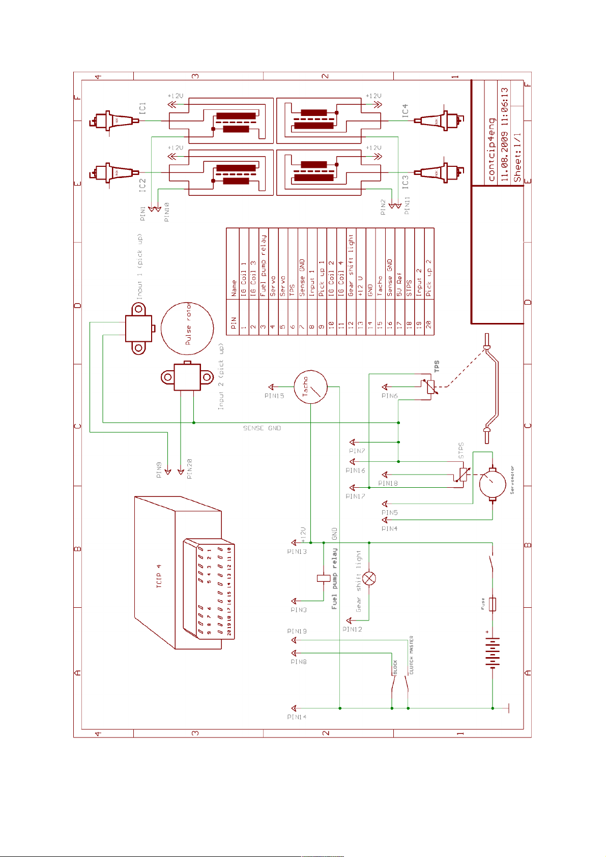
One outlet of the CKPS should e connected to connector (9) and the other one should e connected to SENSE
GND (7, 16). See following the chart. For system with two pick-ups should e one outlet of the second pick-up
connected to connector (20) and the other one should e connected to SENSE GND (7, 16). See following the
chart.
Switc ing inputs 1 and 2.
Unit has two multiuse switching inputs. These inputs can initialize some function (for example KILL switch,
CLUTCH MASTER, locking for side stand switch ...) One outlet of first switch should e connected to
connector (8) and other one should e connected to GND (14). One outlet of second switch should e connected
to connector (19) and other one should e connected to GND (14). Required function can e set y software
TCIP4.EXE.
Ignition coils IC 1, IC 2, IC 3, IC 4 outputs
One outlet of ignition coil 1 should e connected to key switched + 12 V and the other one should e connected
to corresponding connector IC 1 (1).
One outlet of ignition coil 2 should e connected to key switched + 12 V and the other one should e connected
to corresponding connector IC 2 (10).
One outlet of ignition coil 3 should e connected to key switched + 12 V and the other one should e connected
to corresponding connector IC 3 (2).
One outlet of ignition coil 4 should e connected to key switched + 12 V and the other one should e connected
to corresponding connector IC 4 (11).
Excitation (dwell time) of ignition coil can e set to short/long/manual/auto y software TCIP4.EXE. Short
dwell time is for ignition coil with primary coil resistance less than 2 Ohm. Long dwell time is for ignition coil
with primary coil resistance higher than 2 Ohm. If long time is used for coil with primary resistance less 2 Ohm,
coil can e destroyed. If it is used short time for coil that desire long dwell time, the energy of spark could e
small especially in high rpm. You can set dwell time manually also. Next option is use automatics determination
of dwell time. Details are in Software section.
1

Revolution indicator - TACHO output.
The revolution indicator output is compati le with most of oard devices used on motor ikes. Pulse num er for
one revolution and corrections is set within TCIP4.EXE software. TACHO output should e connected to
connector (15).
The revolution indicator output is not compati le with oard devices used on old Hondas from a out 1980. (Bike
ignition units with Oki 16pinovým connector).The unit TCIP4 can e equipped revolution indicator output that is
compati le with this oard devices on request at an additional cost.
FUEL PUMP RELAY output.
Fuel relay is switch on while the motor is running, for a out 4 s after the unit is switched on and for a out 4
sec. after motor has stopped. One fuel pump relay outlet should e connected to connector (3) and the other one
should e connected to key switched + 12V. Connect the switched fuel pump relay circuit following the
diagram.
Outputs and input for SERVO.
Outputs and input for servo are compati le with most of servo used on motor ikes (e.g.. Yamaha EXUP).
The unit is equipped with servo control only in the 4 channel version. Required course of servos can e
configured in software TCIP4.EXE.
Servo motor outputs are on pins (4) and (5). Power servo position sensor is connected to +5 V pin (17) and
SENSE GND (7, 16). The output of position sensor is connected to the input (18).
Output for GEAR SHIFT LIGHT
Maximal current is 5 A (lamp max. 50 W). Revolution for gearshift light is set y software TCIP4.EXE.
One outlet of gearshift light should e connected to connector (12) and other to switched +12 V.
WIRE COLOUR pin no.
in connector
NAME DESCRIPTION
orange 1 IC 1 inductive coil 1
yellow/ lack 2 IC 3 inductive coil 3
violet 3 FUEL PUMPE RELAY output for fuel pump relay
green 4 M output for servomotor
green 5 M output for servomotor
grey 6 TPS throttle position sensor
lue or light lue 7 SENSE GND ground for sensors
lack 8 INPUT 1 switching input 1
yellow 9 CKPS (1) input for pick-up (1)
white 10 IC 2 inductive coil 2
red/ lack 11 IC 4 inductive coil 4
lue/white 12 GEAR SHIFT LIGHT output for gear shift light
red 13 + 12 V supply 12 V
lue 14 GND ground
green/yellow 15 TACHO output for tachometer
lue or light lue 16 SENSE GND ground for sensors
white/red 17 + 5 V supply for sensors
white/ lue 18 STPS servo position sensor
grey/red 19 INPUT 2 switching input 2
rown 20 CKPS (2) input for pick-up (2)
2
3

SOFTWARE TCIP4.EXE
Pull down menus
File:
New - default settings
New for actual page - default settings for actual page only
Open - to open data file
Open from exe dir - to open a data file from the same location with the location of the control software.
` Offer 10 most recently opened data files.
Open for actual page - to open data file for actual page only
Save - to save data file
Save to exe dir - save data file to the same location with the location of the control software.
Print - prints the current settings
Exit - exits the program
Clicking New results in default settings of all parameters. They value for four-stroke engine without TPS.
Com: - includes items Com1 to Com30 and Com Auto - this is for selection of
communication port. For PC without COM (USB only) you need the apply a USB to
RS232 adapter which we can supply.
Device:
Read - reads data from the unit
Verify - compares data in PC with data in the unit
Program - sends data to the unit and conducts verification
Tools: - includes items of collective settings and Undo and Redo tools
Language: - language settings: Englis , German and Czec
Help:
Help - opens assem ly guide (this file)
About t e program - data on the software (version, date)
Icons menus
- default settings
Warning!!! Clicking this icon results in automatic default settings of all parameters
- opens data file
- saves data file
- prints the current settings
- Undo and Redo tools
- see pull down menu Device
Tab s eet Miscellaneous
Limiter - sets revolution of classic starting limiter
Clutc master time - sets ignition switch off period during gear shift
Clutc master pause - sets time of insensi ility after gear shift
Revolutions wit out ignition - sets num er of starting revolution without ignition
Sensor - choose sensor input – no or TPS. That input can e used for advance maps
definition.
4

- limit TPS voltage values can e set here [mV]
- measures and sets 0% TPS (supply on, unit connected with PC, no gas)
- measures and sets 100% TPS (supply on, unit connected with PC, full gas)
Dwell - sets excitation of induction coils
S ort - for coils with resistance lower than 2 ohms.
dwell time 1 ms with the dynamic addition 12%.
Long - for coils with a resistance greater than 2 ohms.
dwell time 3ms with the dynamic addition 12%.
Manual - the a ility to manually determining the excitation time
Auto - automatic dwell time determination. Unit determines optimal dwell time y
measure dynamic current in channel 1. With that choice the spark-coil has to
e connected to channel 1.
Dwell correction parameter [%] - automatically determined dwell time can e corrected percentage.
Dwell time parameter [µs] - requested dwell time
Dwell dynamic addition [%] - dwell addition to compensate uneven engine running at low speed
Max dwell time [µs] - Dwell time limitation, including dynamic addition
Max rpm for dwell by lobe - max rpm definition - the start ignition sequence of coils excitation will e
used up to the speed. Generating y a fixed angle with the virtual lo e
definition. The virtual lo e is defined in the configuration of the sensor
system (see ta sheet Bike).
Inputs for neutral and side stand - Logic of inputs is set for neutral and side stand. The ignition is not locked
if at least one input is grounded.
Input 1 - choice of input 1 function
Input 2 - choice of input 2 function
No reading - reading is not allowed (after programming with this option data cannot e
retrieved from the unit)
Gears ift lig t [rpm] - sets revolution of gearshift light
Correction - correction of advance for cylinders [°]
Compensation - fervency compensation of unit inputs (for compensation of various delays of
input signal for various sensor systems).
Tab s eet Bike
C oice of Motorbike - motor ike type selection
Tac ometer output:
pulses per revolution - pulses for tachometer per revolution
correction - percentage tachometer correction
Polarity of pickup - sensor polarity selection
Plus - designed for sensor connection, where:
lo e is getting near to sensor - generates positive voltage,
lo e is moving away of sensor - generates a negative voltage
Minus - designed for sensor connection, where:
lo e is getting near to sensor - generates negative voltage,
lo e is moving away of sensor - generates a positive voltage
Auto - Unit determines correct polarity automatically. (Algorithms supposes the
summary of lo es angles is less to 180 degrees)
5

Pickup interc ange - exchanges the inputs for the crankshaft position sensor (pin 9 and pin 20).
No polarity c eck - the unit (according to the shape of the signal) controls the polarity of the pickup sensor. If
the actual polarity of the sensors is other than that selected, the unit lock the ignitions. This option cancels this
locking of the ignition.
Interlock input - This option only works with the pickup system "1 lo e, 2 pickup sensors". With some
motorcycle (e.g. Ducati) during the increased level of the elektromagnetic interference (eg during ignitions) can
occur an unwanted activation the pickup input (especially the input which is not active at the moment). This
option prevents this unwanted activation, ecause during activation of input 1 is input 2 is locked for activation
(and vice versa). In com ination with automatic means for determining of polarity sensors, this option can cause
pro lems.
Spark possible before lobe - standard operation of the unit is such that the spark can take place only after the
eginning of the section for the virtual lo e. This option lets you ignite even efore the eginning of the virtual
lo e. Unfortunately, than the virtual lo e is 360° long, which significantly affects the accuracy of ignition
(especially at low revolutions).
Lower advance by start - this option decreases (shifts) the start advance to the next pulse edge over the
standard position in of start advance.
Valid only for starting revolutions (revolutions less than 500 RPM). This option can e used especially for large
single-cylinder engines to prevent kick- ack when starting el. starter. You can use this option only for some
pickup systems.
Special dwel by start - This option can e used to reduce the current load of the ignition coil at the start of the
pickup systems where the virtual lo e is too wide.
Commonly unit at starting revolutions loads the ignition coil from the eginning of the virtual lo e until the
ignition at the end of the virtual lo e. With this option, the unit egins to load at the end of the virtual lo e, loads
2 ms and then comes the ignition. Valid only for starting revolutions (revolutions less than 500 RPM). This
option partially reduced the advance for the startup revolutions (due to delay of 2 ms). .
Compensation - units input circuits respond differently to pickup systems with different num ers of pulse lo e.
The result can e a slight deviated from the desired advance dependent on revolutions. Dependence on
revolutions can e corrected y this compensation.
C oice of pickup system - Choice of pickup system for certain motorcycle
Pulses per revolution - Setting of tachometer output
Correction - Correction of tachometer in %
Sync ronization description - Here you can create a special specification of synchronization (only for
choice „Special petting“ in Motor ike type) – Attention, experienced users
only.
In the left side down are some statistic values of unit. That is read out even if versions of PC software and
firmware are not compati le, the correct connection is necessary.
- TCIP4 unit name
- Date of firmware version
- Num er of times the unit has een programmed
Tab s eet Advance map
Advance map
TP map includes 100 adjusta le advance options (in relation revolution and throttle position). If TPS is not used,
map is degraded to 10 point curve. When motor is running the actual segment is highlighted in map (curve).
Tools for group manipulation and view tools are on the top of sheet. For group selection (rows, columns, free
shape group), dragging and stretching use mouse (adding with ctrl) as commonly is used in office spreadsheet.
Mouse wheel or pop-up uttons can increment and decrement also all group. Right mouse click shows pull-down
menu with all availa le functions.
6

Base advance - setting of ase advance
BASE
ADVANCE
Tab s eet Servo
Servo enable - software activation of servo controller
Servo curve
10 adjusta le options for revolution/required voltage of servo position sensor. When the motor is running current
segment is highlighted in the servo curve. Tools for group manipulation and view tools are on the top of sheet.
For group selection (columns, free shape group), dragging and stretching use mouse (adding with ctrl) as
commonly is used in office spreadsheet. Mouse wheel or pop-up uttons can increment and decrement also all
group. Right mouse click shows pull-down menu with all availa le functions.
Hysteresis - fineness of servo driver steps can e set here
!!!Warning!!! - in case you set too low value there is a risk of servo oscillation
Monitor
Monitor is located on the right and lower side of the screen – sensor values and motor operational characteristics
can e o served here. Should there e No connection wit PC prompt displayed in the upper right corner, the
unit is not connected.
File: - full path of using file
Programming after a c ange - automatic programming settings (after every change)
RPM - Motor revolution [1/min]
TP - Throttle position [%]
Advance 1 to 4 - Ignition advance of each cylinder [°]
Pick up 1 - Display whether pick up 1 is running or stopped
Pick up 2 - Display whether pick up 2 is running or stopped
U- Supply voltage [V]
Servo required - Required value of servo position sensor
Servo measured - Measured value of servo position sensor
Blocking - Blocking activation signal
Gear s ift lig t - signalization of switching gear shift stump
Fuel pump - signalization of switching fuel pump stump
Clutc master - signalization of activation of clutch master
Kill switc - signalization of activation of locking
7
Other Sparker Motorcycle Accessories manuals


