OM-235 368 Page 1
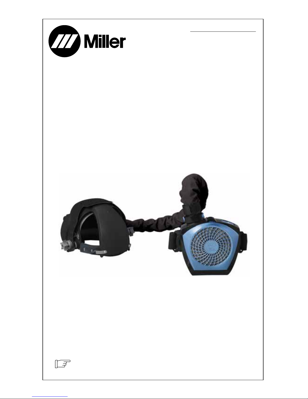
SECTION 1 −HELMET COOLER SAFETY PRECAUTIONS −
READ BEFORE USING
Protect yourself and others from injury — read and follow these precautions.
1-1. Symbol Usage Helmet Cooler 2009−10
This group of symbols means Warning! Watch
Out! ELECTRIC SHOCK, MOVING PARTS,
and HOT PARTS hazards. Consult symbols
and related instructions below for necessary
actions to avoid the hazards.
.Indicates special instructions.
DANGER! −Indicates a hazardous
situation which, if not avoided, will
result in death or serious injury. The
possible hazards are shown in the
adjoining symbols or explained in
the text.
Indicates a hazardous situation
which, if not avoided, could result in
death or serious injury. The possible
hazards are shown in the adjoining
symbols or explained in the text.
NOTICE −Indicates statements not related to
personal injury.
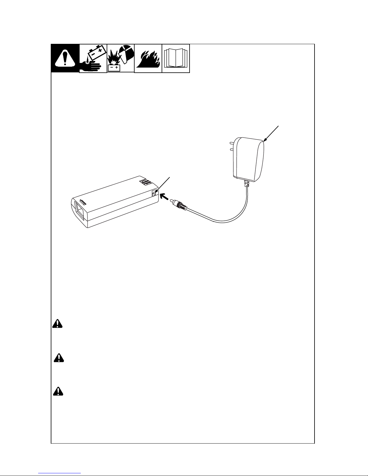
1-2. Hazards
Only qualified persons should install, operate, maintain, and repair this unit.
READ INSTRUCTIONS.
DRead and follow all labels and the Owner’s Manual carefully before installing,
operating, or servicing unit. Read the safety information at the beginning of
the manual and in each section.
DUse only genuine replacement parts from the manufacturer.
DPerform maintenance and service according to the Owner’s Manuals, industry standards,
and national, state, and local codes.
HELMET COOLER MISUSE can be hazardous.
Welding produces fumes and gases. Breathing these fumes and gases can be haz-
ardous to your health.
DRead and follow these instructions and the safety labels carefully. This
product is intended for use as a cooling device only. It is not a respiratory protective device and
does not protect the user from airborne contaminants. Have an industrial hygienist test the air in
your facility to determine if respiratory protection is required to provide adequate protection from
contaminants in your environment. With cooling system-equipped helmet on, also test the air in-
side the helmet to determine if respiratory protection is required. If you have questions about the
type of respiratory protection equipment required, consult your safety director and an Industrial
Hygienist.
DDo not use this product where there is danger of fire or explosion.
DDo not use this product in windy conditions or negative pressure inside the hood may draw in
contaminants from the outside air.
DDo not use this product without a properly installed spark guard unless the unit is designed and
intended to be used without one. Without the spark guard (on applicable products), welding
sparks may ignite the filter or damage the filter.
DThis product does not supply oxygen. Do not use this product where oxygen levels are 19.5% or
lower, where contaminant levels are unknown or are immediately dangerous to life or health
(IDLH), or where the contaminant levels exceed the equipment specifications.
DDo not enter a work area until you are sure the equipment is correctly assembled, working proper-
ly, and properly worn.