Sparker TCI-P4 User manual

1
w
w
ww
w
ww
w
w
.
.
.
-
--
-
-
--
-
-
--
-p
pp
p
p
pp
p
p
pp
pr
rr
r
r
rr
r
r
rr
ro
oo
o
o
oo
o
o
oo
o-
--
-
-
--
-
-
--
-m
mm
m
m
mm
m
m
mm
mi
ii
i
i
ii
i
i
ii
il
ll
l
l
ll
l
l
ll
ll
ll
l
l
ll
l
l
ll
le
ee
e
e
ee
e
e
ee
e.
..
.
.
..
.
.
..
.
d
d
de
e
e
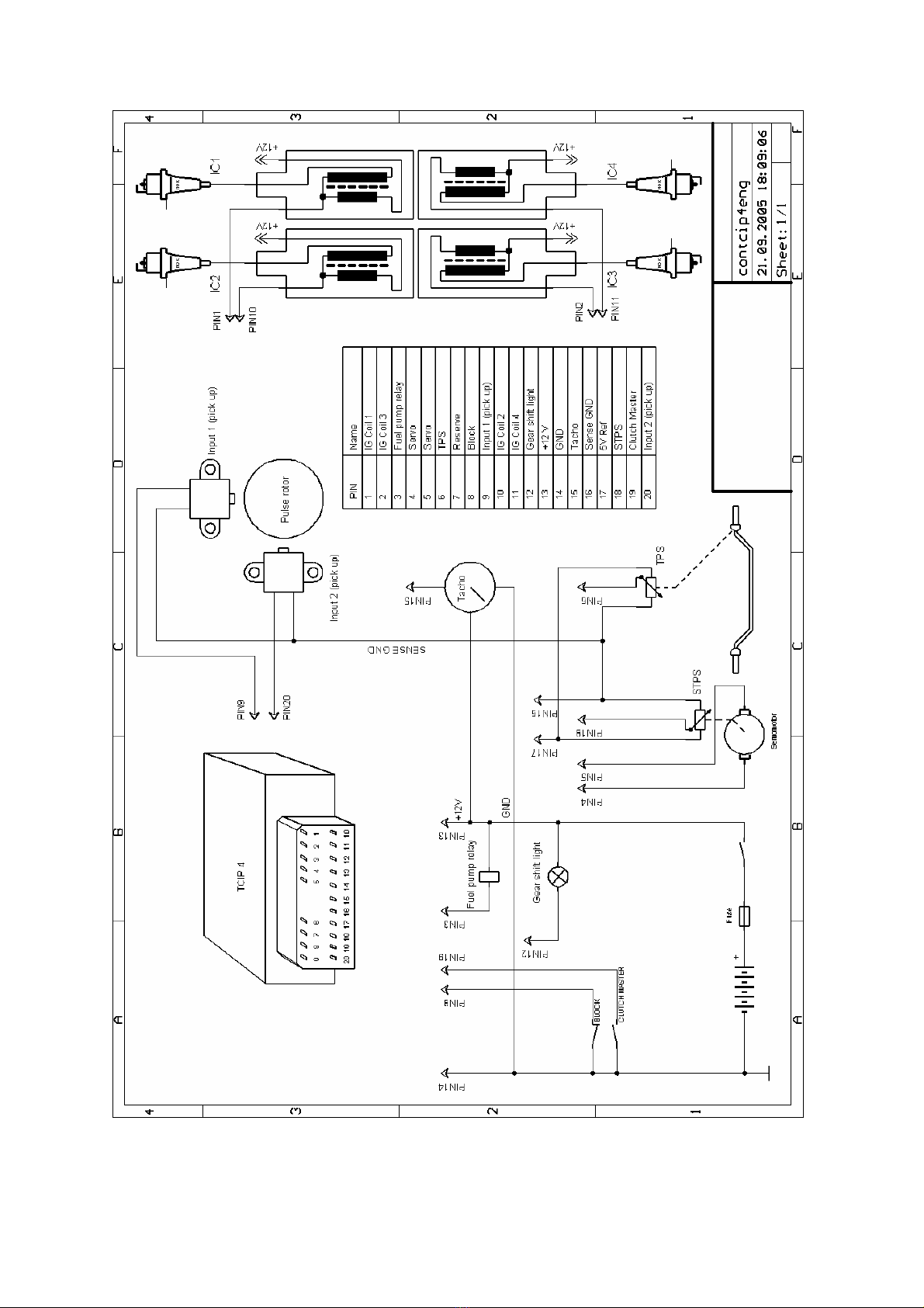
SPARKER TCI-P4
SPARKER TCI-P4 is an inductive ignition unit for road motorcycle. The ignition unit can be set by a computer PC with a
program TCIP4.EXE. Advance (time of ignition) can be set as a function of revolution or as a function of revolution and
TPS (throttle position sensor). Ignition contains outputs for tachometer, fuel pump relay, and servo controller. It contains
also two inputs for blocking of ignition and one for servo controller. It is by the time of programming connected with
computer PC by serial port (COM). The program TCIP4.EXE is included to ignition unit.
HARDWARE
Pick up system.
Ignition can have maximal four channels. Standard version has two channels (four-cylinder engine). Ignition can be
programmed for many pickup systems. Most of them can be choose directly from list in program TCIP4.EXE others can be
set by special procedure (also by program TCIP4.EXE).
Supply voltage +12 V input.
Supply voltage must be within 8 – 18 voltage range. In this range the unit is able to provide optimal control of all the
processes. Supply voltage is connected by positive outlet to +12 V (13) and by negative outlet to GND (14).
Throttle position sensor TPS input.
An input is ready for standard TPS sensors used on motorbikes. It is designed for voltage range 0 - 5 V. Sensor settings for
0 % and 100 % is set by TCIP4.EXE software.
TPS is powered by referential voltage + 5 V (17) and SENSE GND (16). Sensor outlet will be connected to connector (6).
Crankshaft position sensor CKPS input.
An input is ready for standard pickup sensors used on motorbikes as CKPS.
One outlet of the CKPS should be connected to connector (9) and the other one should be connected to SENSE GND (16).
See following the chart. For system with two pick-ups should be one outlet of the second pick-up connected to connector
(20) and the other one should be connected to SENSE GND (16). See following the chart.
Blocking input.
One outlet of blocking switch (for example side stand switch) should be connected to connector (8) and other one should be
connected to SENSE GND (14) or GND (16). If the blocking switch is active the ignition is blocked. Opposite polarity of
blocking input can be set by software TCIP4.EXE.
Induction coils IC 1, IC 2, IC 3, IC 4 outputs
One outlet of induction coil of cylinder 1, 4 should be connected to key switched + 12 V and the other one should be
connected to corresponding connector IC 1, 4 (1). One outlet of induction coil of cylinder 2, 3 should be connected to key
switched + 12 V and the other one should be connected to corresponding connector IC 2, 3 (10).
Excitation (dwell time) of induction coil can be set to short or long by software TCIP4.EXE. Short dwell time is for
induction coil with primary coil resistance less than 2 Ohm. If long time is used for that one coil, coil can be destroyed. If it
is used short time for coil that desire long dwell time, the energy of spark could be small especially in high rpm.
Revolution indicator - TACHO output.
The revolution indicator output is compatible with most of board devices used on motorbikes. Pulse number for one
revolution and corrections is set within TCIP4.EXE software. TACHO output should be connected to connector (15).
FUEL PUMP RELAY output.
Fuel relay is switch on while the motor is running, for about 4 s after the unit is switched on and for about 4 sec. after motor
has stopped. One fuel pump relay outlet should be connected to connector (3) and the other one should be connected to key
switched + 12V. Connect the switched fuel pump relay circuit following the diagram.

2
w
w
ww
w
ww
w
w
.
.
.
-
--
-
-
--
-
-
--
-p
pp
p
p
pp
p
p
pp
pr
rr
r
r
rr
r
r
rr
ro
oo
o
o
oo
o
o
oo
o-
--
-
-
--
-
-
--
-m
mm
m
m
mm
m
m
mm
mi
ii
i
i
ii
i
i
ii
il
ll
l
l
ll
l
l
ll
ll
ll
l
l
ll
l
l
ll
le
ee
e
e
ee
e
e
ee
e.
..
.
.
..
.
.
..
.
d
d
de
e
e
Outputs and input for SERVO.
Outputs and input for servo are compatible with most of servo used on motorbikes (e.g.. Yamaha EXUP). Ignition with
servo is only done on demand.
Output for GEAR SHIFT LIGHT
Maximal current is 5 A (lamp max. 50 W). Revolution for gearshift light is set by software TCIP4.EXE.
One outlet of gearshift light should be connected to connector (12) and other to switched +12 V.
CLUTCH MASTER input.
One outlet of CLUTCH MASTER switch should be connected to connector (19) and the other one should be connected to
SENSE GND (16) or GND (14). If CLUTCH MASTER switch is activated, the unit blocks ignition for a defined period of
time. This provides for higher gearshift without clutch and gas shut-off, thus minimizing the time losses during gear
shifting. Blocking time can be adjusted within TCIP4.EXE software. Reverse polarity of the CLUTCH MASTER switch
can be configured within TCIP4.EXE software.
WIRE COLOUR
pin no.
in connector
NAME DESCRIPTION
orange 1 IC 1 inductive coil 1,4
2 IC 3 not connected in standard
violet 3 FUEL PUMPE RELAY
inductive coil 2,3
green 4 M output for servomotor
green 5 M output for servomotor
grey 6 TPS throttle position sensor
7 not connected
black 8 BLOCK blocking input
yellow 9 CKPS (1) input for pick-up (1)
white 10 IC 2 inductive coil 2,3
11 IC 4 not connected in standard
12 GEAR SHIFT LIGHT output for gear shift light
red 13 + 12 V supply 12 V
blue 14 GND ground
green/yellow 15 TACHO output for tachometer
blue 16 SENSE GND ground for sensors
white/red 17 + 5 V supply for sensors
white/blue 18 STPS servo position sensor
19 CLUTCH MASTER input for gear shift sensor
brown 20 CKPS (2) input for pick-up (2)
3

4
w
w
ww
w
ww
w
w
.
.
.
-
--
-
-
--
-
-
--
-p
pp
p
p
pp
p
p
pp
pr
rr
r
r
rr
r
r
rr
ro
oo
o
o
oo
o
o
oo
o-
--
-
-
--
-
-
--
-m
mm
m
m
mm
m
m
mm
mi
ii
i
i
ii
i
i
ii
il
ll
l
l
ll
l
l
ll
ll
ll
l
l
ll
l
l
ll
le
ee
e
e
ee
e
e
ee
e.
..
.
.
..
.
.
..
.
d
d
de
e
e
SOFTWARE TCIP4.EXE
Pull down menus
File – includes items New - default settings
Open - opens data file
Save - saves data file
Print - prints the current settings
Print all - prints the current settings all tab sheets
Exit - exits the program
Clicking New results in default settings of all parameters. They value for four-stroke engine without TPS.
Port – includes items Com1 to Com10- selection of communication line
For PC without COM (USB only) apply adapter USB/RS232.
Device – includes items Read - reads data from the unit
Verify - compares data in PC with data in the unit
Program - sends data to the unit and conducts verification
Tools –include items of collective settings
Language – language settings: English, German, French and Czech
Help – includes items Help - opens assembly guide (this file)
About the program - data on the software (version, date)
Icons menus
- default settings
Warning!!! Clicking this icon results in automatic default settings of all parameters
- opens data file
- saves data file
- prints the current settings
- see pull down menu Device
Tab sheet Miscellaneous
Limiter - sets revolution of classic starting limiter
Revolutions without ignition - sets number of starting revolution without ignition
Excitation long - sets long excitation of induction coils
Programming after a change - automatic programming settings (after every change)
No reading - reading is not allowed (after programming with this option data cannot be
retrieved from the unit)
Switch activation - input logic settings (if the box is checked the function is activated by switch on input)

5
w
w
ww
w
ww
w
w
.
.
.
-
--
-
-
--
-
-
--
-p
pp
p
p
pp
p
p
pp
pr
rr
r
r
rr
r
r
rr
ro
oo
o
o
oo
o
o
oo
o-
--
-
-
--
-
-
--
-m
mm
m
m
mm
m
m
mm
mi
ii
i
i
ii
i
i
ii
il
ll
l
l
ll
l
l
ll
ll
ll
l
l
ll
l
l
ll
le
ee
e
e
ee
e
e
ee
e.
..
.
.
..
.
.
..
.
d
d
de
e
e
TPS - limit TPS voltage values can be set here [mV]
- measures and sets 0% TPS (supply on, unit connected with PC, no gas)
- measures and sets 100% TPS (supply on, unit connected with PC, full gas)
File: - full path of using file
Tab sheet Motorcycle
Choice of pickup system - Choice of pickup system for certain motorcycle
Pulses per revolution - Setting of tacho output
Correction - Correction of tacho in %
Tab sheet Advance map
Advance map
TP map includes 100 adjustable advance options (in relation revolution and throttle position). Collective setting of the
whole column is possible using the arrows under columns. Collective adjustment of the whole map can be done by
collective change tool (+and –buttons with selection All)
When the motor is running and PC connected with the unit current segment in the fuel map is highlighted. Use of collective
change tool +and –button without selection All - just the current segment will be changed.
TPS - option advance map/advance curve
Base advance - setting of base advance
BASE
ADVANCE
Tab sheet Servo
Servo allowed - software activation of servo controller
10 adjustable options for revolution/required voltage of servo position sensor
Collective adjustment of the whole servo curve can be done by collective change tool (+and –buttons with selection All)
When the motor is running current segment is highlighted in the servo curve. Use of collective change tool +and –button
without selection All - just the current segment will be changed.
Hysteresis – fineness of servo driver steps can be set here
!!!Warning!!! - in case you set too low value there is a risk of servo oscillation

6
w
w
ww
w
ww
w
w
.
.
.
-
--
-
-
--
-
-
--
-p
pp
p
p
pp
p
p
pp
pr
rr
r
r
rr
r
r
rr
ro
oo
o
o
oo
o
o
oo
o-
--
-
-
--
-
-
--
-m
mm
m
m
mm
m
m
mm
mi
ii
i
i
ii
i
i
ii
il
ll
l
l
ll
l
l
ll
ll
ll
l
l
ll
l
l
ll
le
ee
e
e
ee
e
e
ee
e.
..
.
.
..
.
.
..
.
d
d
de
e
e
Monitor
Monitor is located on the right and lower side of the screen – sensor values and motor operational characteristics can be
observed here. Should there be No connection with PC prompt displayed in the upper right corner, the unit is not
connected.
RPM - motor revolution [1/min]
TP - Throttle position [%]
Advance - Ignition advance [°]
Pick up 1 - display whether pick up 1 is running or stopped
Pick up 2 - display whether pick up 2 is running or stopped
U- supply voltage [V]
Servo required - Required value of servo position sensor
Servo measured - Measured value of servo position sensor
Blocking - Blocking activation signal
Number of programming - Number of times the unit has been programmed
1M o t o r - S p o r t – S e r v i c e Stand: 01.10.2005
Markus Schmitt, Am Frankengrund 1, 36093 Künzell
Tel.: 0661-93350031 Mobil: 0173-9438673 FAX 0661-93350032
millemille
mille
Table of contents
Other Sparker Motorcycle Accessories manuals


Popular Motorcycle Accessories manuals by other brands


Bell
Bell FULL FACE user manual

SRC
SRC T-S1200-14-01-SL quick start guide

Vinz
Vinz Laghi instruction manual

Custom Dynamics
Custom Dynamics Street Magic Amber Brightsides Install instructions

Wolfman
Wolfman E-Base B200 Mounting instructions

hepco & becker
hepco & becker 6004519 00 02 installation instructions