SPARTAN sport 1332 User manual

E L LIPTIC AL TR AINER
ITEM NO : 1 3 3 2

O W N E R’ S
M A N U A L
IMPORTANT: Read all instructions carefully before using this product. Retain this
owner’s anual for future reference.
The specifications of this product ay vary fro this photo, subject to change without
notic
e.
TABLE OF CONTENTS
IMPORTANT SAFETY INSTRUCTIONS ------------------------------------------- 2
PARTS LIST ------------------------------------------------------------------------------- 3
HARDWARE PACKING LIST --------------------------------------------------------- 5
TOOLS -------------------------------------------------------------------------------------- 6
OVERVIEW DRAWING ----------------------------------------------------------------- 7
ASSEMBLY INSTRUCTIONS --------------------------------------------------------- 8
OPERATING THE COMPUTER ------------------------------------------------------ 15
AD USTMENTS -------------------------------------------------------------------------- 17
MAINTENANCE -------------------------------------------------------------------------- 18
TROUBLESHOOTING ------------------------------------------------------------------ 18
WARM UP AND COOL DOWN ROUTINE ----------------------------------------- 19
IMPORTANT SAFETY INSTRUCTIONS
Basic precautions should al ays be follo ed, including the follo ing important
safety instructions hen using this equipment: Read all instructions before using
this
equipment.

1. Read all instructions and follow it carefully before using this equipment. Make sure the
equipment is properly assembled and tightened before use.
2. Before exercise, in order to avoid injuring the muscle, warm-up exercise is necessary.
Refer to the Warm Up and Cool Down Routine pages. After exercise, relaxation of the
body is suggested for cool-down.
3. Please make sure all parts are not damaged and fixed well before use. This equipment
should be placed on a flat surface when using. Using a mat or other covering material
on the ground is recommended.
4. Please wear proper clothes and shoes when using this equipment; do not wear clothes
that might catch any part of the equipment.
5. Do not attempt any maintenance or adjustments other than those described in this
manual. Should any problems arise, discontinue use and consult your local dealer.
6. Be careful when step on or leave the pedal always hold the handlebars first. Make the
pedal at your side at the lowest position, step on the pedal, and stride over the main
frame then step on the other pedal. When using, please hold the handlebar by hands,
make the pedals running smoothly by push or pull handlebars, then run the equipment
regularly by cooperation of hands and feet. After exercise, please also make one
pedal at the lowest position and leave your foot on the higher pedal first and then
another.
7. Do not use the equipment outdoors.
8. This equipment is for household use only.
9. Only one person at a time should use this equipment.
10. If you feel any chest pains, nausea, dizziness, or short of breath, you should stop
exercising immediately and consult your physician before continuing.
11. Care should be taken in mounting or dismounting the equipment.
12. Do not allow children to use or play on the equipment. Keep children and pets away
from the equipment while in use. This machine is designed for adults use only. The
minimum free space required for safe operation is not less than two meters.
13. The maximum weight capacity for this product is 250 lbs/110 kgs.
WARNING: Before beginning any exercise program consult your
physician. This is especially important for the persons ho are over 35 years old or
ho have pre-existing health problems. Read all instructions before using any
fitness equipment.

CAUTION: Read all instructions carefully before operating this product.
Retain this O ner’s Manual for future reference.
PARTS LIST
No. Description Qty No. Description Qty
001 Main Frame
Hlavný rám
Hlavní rám
1 022 Washer Ø16xØ8x1.5
podložka
podložka
2
002L Left Foot Bar
Levá tyč
lavá tyč
1 023 Bolt M8x45
Šroub
Skrutka
2
002R Right Foot Bar
pravá tyč
pravá tyč
1 024 Nylon Nut M6
nylonová matice
nylonová matica
10
003L Left Handrail Arm
levá paža madla
lavá paža madla
1 025 Washer Ø6
podložka
apodložka
7
003R Right Handrail Arm
pravá paža madla
pravá paža madla
1 026 Bolt M6x40
Šroub
skrutka
6
004L Left Handrail Ø32x1.5
levá paže madla
lavá paža madla
1 027 Tension Cable L=1800
napínací kabel
napínací kábel
1
004R Right Handrail Ø32x1.5
pravá paže madla
pravá paža madla
1 028 Cap S13
uzávěr
uzáver
2
005 Front Post
přední pozice
predná pozícia
1 029 Screw ST4.2x25
šrioub
skrutka
11
006 Handlebar Ø25x1.5
řidítká
riadidlá
1 030L Foot Bar Cover-A
nožní kryt-A
nožný krat-A
2
007 Front Stabilizer Ø60x1.5x480
Rovný stabilizátor
rovný stabilizátor
1 030R Foot Bar Cover-B
Nožný kryt -B
nožný kryt-B
2
008 Rear Stabilizer
zadní stabilizátorazadný
stabilizátor
1 031 Big Washer Ø6
velká podložka
velká podložka
2
009 Carriage Bolt M8x70
vratový šroub
vratová skrutka
2 032 Bolt Ø15.8x62.5
šroub
skrutka
2
010L Front Left Stabilizer End Cap Ø60
prední levý stabilizátor se
1 033 Left Foot Pedal 395x150x65
levý základ pedálu
1

zakončením
predný lavý stabilizátor s
uzáverom
lavý zakladný pedál
010R Front Right Stabilizer End Cap
Ø60
predný pravý stabiolizátor se
zakončením
predný pravý stabilizátor so
zakončením
1 034 Right Foot Pedal 395x150x65
pravý základ pedálu
opravý základ pedálu
1
011 Big Curve Washer Ø20xØ8
veliká okrouhlá podložka
velká oktrúhla podložka
10 035 Rear Left Stabilizer End Cap
Ø60
levý zadní stabilizátor koncovka
lavý zadný stabilizátor koncovka
1
012 Cap Nut M8
převlečná matice
prevlečná matica
2 036 Rear Right Stabilizer End Cap
Ø60
zadní pravý stabilizátor koncovka
zadný pravý stabilizátor
koncovka
1
013L Bolt for left U Shape Bracket 1/2”
Šroub pro levou hranatou závorku
tvaru U 1 /2 "
skrutka pre lavú hranatú zavorku
1 037 Cover Cap Ø40xØ25x10
krytka
krytka
2
013R Bolt for right U Shape Bracket
1/2”
šroub pře pravou hranatou
závorku
skrutka pre pravú hranatú závorku
1 038 Bolt M8x15
šroub
skrutka
8
014L Left Nylon Nut 1/2”
nylonová matice
nylonová matica
1 039 Powder Metal Bushing
Ø14.2xØ10.2x10
kovové pouzdro
kovové púzdro
4
014R Right Nylon Nut 1/2”
nylonová matice
nylonová matica
1 040 Bolt M8x20
šroub
matice
2
015 Wave Washer Ø28xØ17x0.3
vlnená podložka
vlnená podložka
2 041 Spring Washer Ø8
napínací podložka
napínacia podložka
8
016 Powder Metal Bushing
Ø24.5xØ16x14
4 042 Washer Ø38x3
podložka
podložka
2
017 Spring Washer Ø20
napínací podložka
2 043 Powder Metal Bushing 4

napínacia podložka Ø38xØ32xØ19x14
018 Idler Pulley
napínací kladka
napínacia kladka
1 044 Bolt M6x35
šroub
skrutka
4
019 Washer 7/8"
podložka
podložka
1 045 Curve Washer Ø6
kulatá podložka
gulatá podložka
4
020 U Shape Bracket
držák tvar-U
držiak v tvare-U
2 046 Big Washer Ø8
velká podložka
velká podložka
2
021 Nylon Nut M8
nylonová matice
nylonová matica
2 047 Bolt M6x10
šroub
skrutka
1
PARTS LIST
No. Description Qty No. Description Qty
048 Plastic Bushing
Ø32xØ16x5xØ50
plastové pouzdro
plastové púzdro
2 073 Washer Ø34.5xØ23x2.5
podložka
podložka
1
049L Left Handrail Arm Cover-A
evá paža madla
lavá paža madla
1 074 Hexagon Nut 7/8”
šestihranný šroub
šesthranná skrutka
1
049R Right Handrail Arm Cover-A
pravá paže madla
pravá paža madla
1 075 Belt Pulley with Crank 6.5”/Ø260
řemenice
remenice
1
050L Left Handrail Arm Cover-B
evá paža madla
lavá paža madla
1 076 Bolt M8x25
šroub
skrutka
1
050R Right Handrail Arm Cover-B
pravá paže madla
pravá paža madla
1 077 M10x1 Nut for Flywheel
matice pro setrvačník
matica pre zotrvačník
2
051 Tension Control Knob
Kontrolní knoflík
kontrolné tlačidlo
1 078 Flywheel Ø230x40x32
setrvačník
zotrvačník
1
052 Screw ST4.2x20
šroub
skrutka
4 079 Belt P 380 6
pás
pás
1
053 Computer (HR1581)
počítač
počítač
1 080 Idler Arm
napínací rameno
napínacie rameno
1

054 Rear Decorative Cover for Front
Post
zadní dekorativní kryt
zadný dekoratívny kryt
1 081 Bolt M6x15
šroub
skrutka
2
055 Hand Pulse Sensor with Wire
L=750
ruční pulz
ručný pzulz
2 082 Eyebolt M6x36
šroub s okem
skrutka z okom
2
056 Handrail Foam Grip
Ø31xØ37x480
pěnový držák
penový držák
2 083 Tension Bracket
napětí
napätie
2
057 Handlebar Foam Grip
Ø27xØ33x360
pěnový držák
penový držák
2 084 Nut M6
šroub
skrutka
2
058 Handrail End Cap Ø32x1.5
zakončení držáku
zakončenie držiaka
2 085 Spring Washer Ø6
napínací podložka
napínacia podložka
2
059 Handlebar End Cap Ø28x1.5
řidítká záslepka
riadidlá zakončenie
2 086 Power Metal Bushing Ø18xØ8x5
metální pouzdro
metálové púzdro
4
060 Phillips Self Tapping Screw
ST4.2x25
šroubovák Philips
skrutkovač Philips
6 087 Nut M10
šroub
skrutka
2
061 Curve Washer Ø20xØ5.2
kulatá podložka
gulatá podložka
1 088 Bolt M5x10
šroub
skrutka
4
062 Bolt M5x55
šroub
skrutka
1 089 Bolt M8x10
šroub
skrutka
1
063 Adjustable Leveler M10
nastavení vyrovnání
nastavenie vyrovnania
2 090 Front Decorative Cover for Front
Post
pozice
pozícia
1
064 Extension Sensor Wire L=1100
prodloužený swenzorový drát
predlžený senzorový drot
1 091 Left Decorative Cover
levý dekorativní kryt
lavý dekoratívny
1
065 Sensor with Wire L=1600
senzorový drát
1 092 Right Decorative Cover
pravý dekorativní kryt
1
senzorový drot pravý dekorativny kryt
066 Screw ST2.9x12
šroub
skrutka
2 093 Curve Washer Ø16xØ8
okrouhlí matice
okrúhla matica
2
067 Left Cover
levý kryt
lavý kryt
1 094 Screw ST4.2x12
šroub
skrutka
8
068 Right Cover
pravý kryt
pravý kryt
1 095 Rubber Cover
gumový kryt
gumový kryt
2
069 Bearing Cup
ložiskový pohár
2 096 Bolt M8x70 2
070 Bearing
ložisko
ložisko
2 097 Phillips Self Tapping Screw
ST4.2x20
8
071 Bearing Nut I 15/16”
ložiskový šroub
ložisková skrutka
1 098 Screw ST2.9x16
šroub
skrutka
1
072 Bearing Nut II 7/8”
ložiskový šroub
ložisková skrutka
1
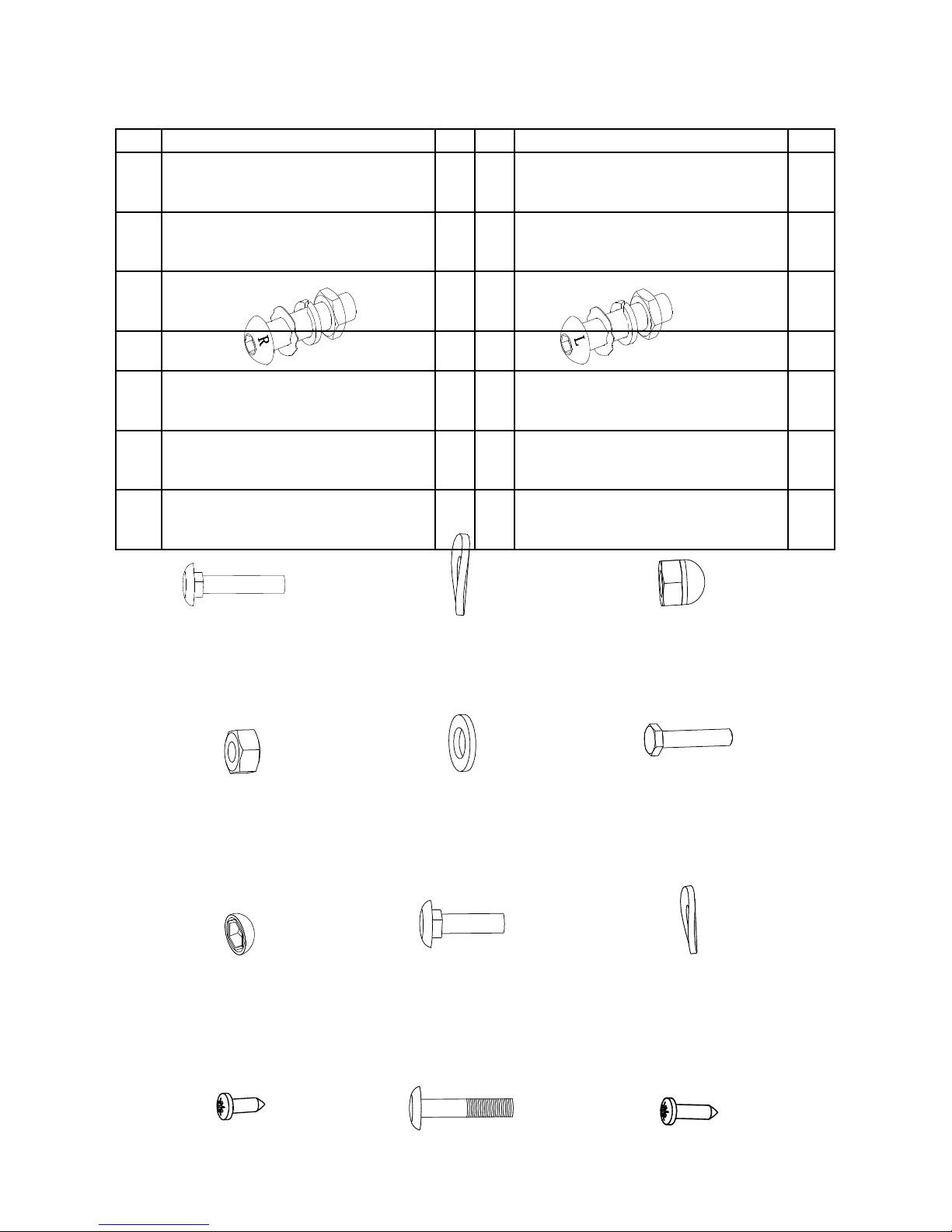
HARDWARE PACKING LIST
(9) Carriage Bolt
M8x70
2 PCS
Vratový šroub
(12) Cap Nut M8
2 PCS
Zakončení šroubu
(24) Nylon Nut M6
10 PCS
Nylonové matice
MATICE
(25) Washer Ø6
6 PCS
po ložka
(26) Bolt
M6x40
6 PCS
šroub
(28) Cap S13
2 PCS
zakončení
(11) Big Curve Washer Ø20xØ8
4 PCS
Velká kulatá po ložka
(44) Bolt M6x35
4 PCS
šroub
(45) Curve Washer Ø6
4 PCS
Okrouhlá po ložka
(94) Screw
ST4.2x12
8 PCS
šroub
(96) Bolt
M8x70
2 PCS
šroub
(97) Phillips Self Tapping Screw
ST4.2x20
4 PCS
Philips samořezný šroub
(13R) Bolt for right U Shape
Bracket 1/2” 1 PC
Šroub tvaru – U
DRŽÁK
(14R) Right Nylon Nut 1/2” 1 PC
(15) Wave Washer
Ø28xØ17x0.3
1 PC
(17) Spring Washer Ø20 1
PC
(13L) Bolt for left U Shape
Bracket 1/2” 1
PC
(14L) Left Nylon Nut 1/2” 1 PC
(15) Wave Washer
Ø28xØ17x0.3
Vlněná podložka
1 PC
(17) Spring Washer Ø20 1
PC

TOOLS
Multi Hex Tool
S10, S13, S17, S19
1 PC
Vícefunkčný
šestihranný klíč
Allen Wrench S6
1 PC
Multifunkčný klúč
Allen Wrench S8
1 PC
Multifunkčný klúč
Multi Hex Tool with Phillips Screwdriver
S10, S13, S14, S15
1 PC
Multifunkčný skrutkovač

OVERVIEW DRAWING

ASSEMBLY INSTRUCTIONS
1. Front and Rear Stabilizers Installation
Position the Front Stabilizer (7) in front of Main Frame (1) and align bolt holes.
Attach the Front Stabilizer (7) onto the front curve of the Main Frame (1) with two M8x70
Carriage Bolts (9), two Ø20xØ8 Big Curve Washers (11), and two M8 Cap Nuts (12).
Tighten cap nuts with the Multi Hex Tool with Phillips Screwdriver provided.
Position the Rear Stabilizer (8) behind the Main Frame (1) and align bolt holes.
Attach the Rear Stabilizer (8) onto the rear curve of the Main Frame (1) with two M8x70
Bolts (96), and two Ø20xØ8 Big Curve Washers (11). Tighten bolts with the S6 Allen
Wrench provided.
Install two M10 Adjustable Levelers (63) and two M10 Nuts (87) onto the Rear Stabilizer
(8).
Hard are:
Tool:
Multi Hex Tool with Phillips Screwdriver
S10, S13, S14, S15
Allen Wrench S6
(96) Bolt
M8x70
2 PCS
(9) Carriage Bolt
M8x70
2 PCS
(12) Cap Nut M8
2 PCS
(11) Big Curve Washer Ø20xØ8
4 PCS
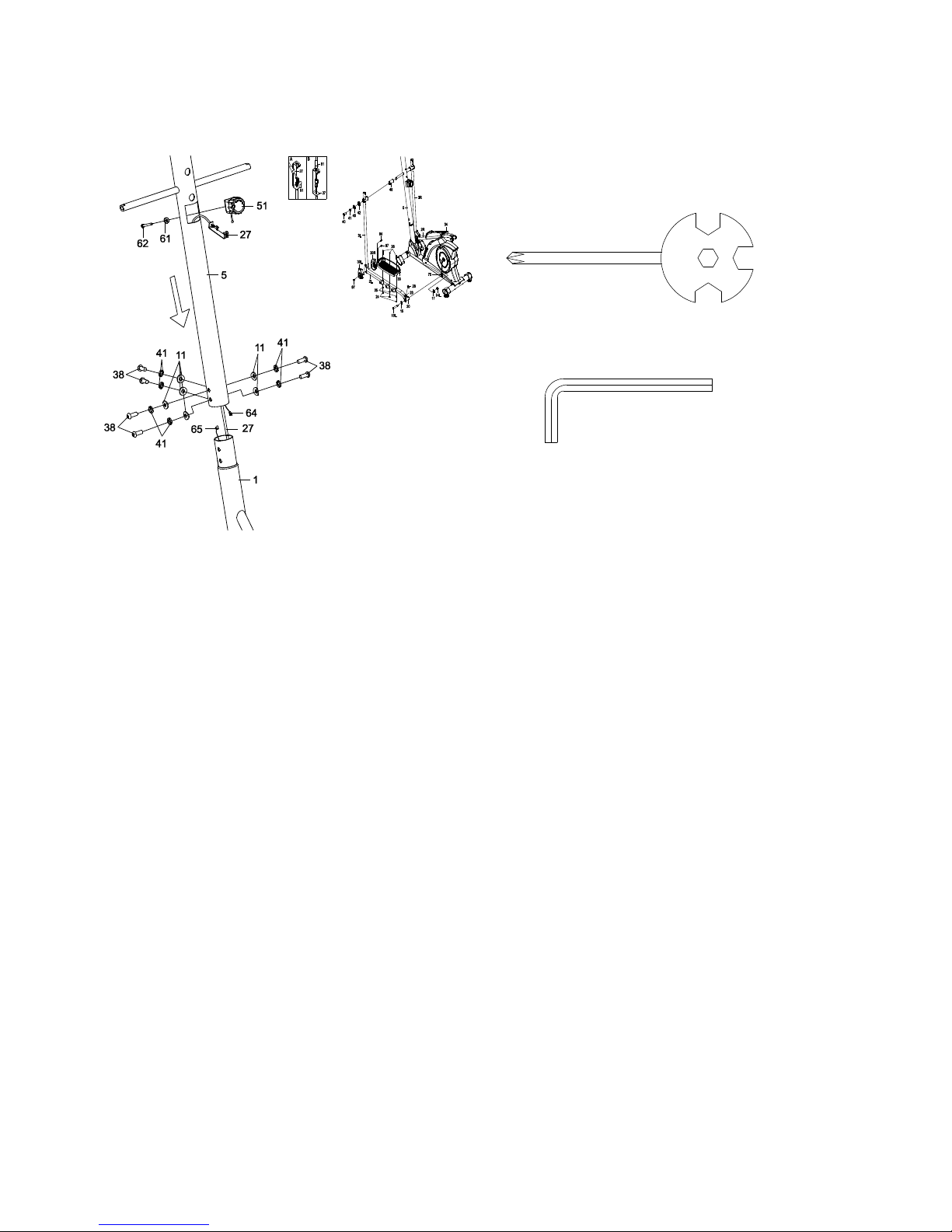
2.
Front Post and Tension Control Knob Installation
Remove six M8x20 Bolts (38), six Ø8 Spring Washers (41), and six Ø20xØ8 Big Curve
Washers (11) from the Main Frame (1). Remove bolts and washers with the S6 Allen
Wrench provided.
Insert the Tension Cable (27) through into the bottom hole of Front Post (5) and pull it out
from the square hole of Front Post (5).
Connect the Sensor Wire (65) from the Main Frame (1) to the Extension Sensor Wire (64)
from the Front Post (5).
Insert the Front Post (5) onto the tube of the Main Frame (1) and secure with six M8x20
Bolts (38), six Ø8 Spring Washers (41), and six Ø20xØ8 Big Curve Washers (11) that were
removed. Tighten bolts and washers with the S6 Allen Wrench provided.
Remove the Ø20xØ5.2 Curve Washer (61) and M5x55 Bolt (62) from the Tension Control
Knob (51). Remove bolt with the Multi Hex Tool with Phillips Screwdriver provided.
Put the cable end of resistance cable of Tension Control Knob (51) into the spring hook of
Tension Cable (27), see Figure A. Pull the resistance cable of Tension Control Knob (51)
up and force it into the gap of metal bracket of Tension Cable (27), see Figure B. Attach
the Tension Control Knob (51) onto the Front Post (5) with the Ø20xØ5.2 Curve Washer
(61)
and M5x55 Bolt (62) that were removed. Tighten bolt and curve washer with the Multi Hex
Tool with Phillips Screwdriver provided.
Tool:
Multi Hex Tool with Phillips Screwdriver
S10, S13, S14, S15
Allen Wrench S6

3. Left/Right Handrail Arms, Left/Right Foot Bars, Left/Right Foot Pedals, and Foot
Bar Covers-A/B Installation
Remove two M8x20 Bolts (40), two Ø8 Spring Washers (41), two Ø8 Big Washers (46), and
two Ø38x3 Washers (42) from the left and right horizontal axes of the Front Post (5).
Remove bolts and washers with the S6 Allen Wrench provided.
Attach the Left Handrail Arm (3L) onto the left horizontal axis of the Front Post (5) with one
M8x20 Bolt (40), one Ø8 Spring Washer (41), one Ø8 Big Washer (46), and one Ø38x3
Washer (42) that were removed. Tighten bolt and washers with the S6 Allen Wrench
provided.
Attach the left U Shape Bracket (20) to the left Crank (75) with one 1/2” Bolt for left U
Shape
Bracket (13L), one Ø28xØ17x0.3 Wave Washer (15), one Ø20 Spring Washer (17), and
one
1/2” Left Nylon Nut (14L). Tighten bolt and nylon nut with the S8 Allen Wrench and Multi
Hex Tool provided. Install a S13 Bolt Cap (28) onto the M8x45 Bolt (23).
NOTE: 1/2” Bolt for left U Shape Bracket (13L) and 1/2” Bolt for right U Shape Bracket
(13R) are marked “R” for Right and “L” for Left.
Attach the Left Foot Pedal (33) onto the Left Foot Bar (2L) with three M6 Nylon Nuts (24),
three Ø6 Washers (25), and three M6x40 Bolts (26). Tighten nylon nuts with the Multi Hex
Tool with Phillips Screwdriver provided.
Attach the Foot Bar Covers-A/B (30L, 30R) onto the Left Foot Bar (2L) with one ST4.2x12
Screws (94) and two ST4.2x20 Phillips Self Tapping Screws (97). Tighten screws with the
Multi Hex Tool with Phillips Screwdriver provided.
Repeat above step to attach the Right Handrail Arm (3R) onto the right horizontal axis of
the
Front Post (5) and right U Shape Bracket (20) to the right Crank (75).
Hard are:
(24) Nylon
Nut M6
6 PCS
(25)
Washer Ø6
6 PCS
(26) Bolt
M6x40
6 PCS
(28) Cap
S13
2 PCS
(13R) Bolt for right U
Shape
Bracket 1/2”
1 PC
(14R) Right Nylon Nut
1/2” 1 PC
(15) Wave Washer
Ø28xØ17x0.3
1 PC
(17) Spring Washer Ø20
1 PC
(13L) Bolt for left U Shape
Bracket 1/2”
1 PC
(14L) Left Nylon Nut 1/2”
1 PC
(15) Wave Washer
Ø28xØ17x0.3
1 PC
(17) Spring Washer Ø20
1 PC
(94) Screw
ST4.2x12
2 PCS
(97) Phillips Self
Tapping Screw
ST4.2x20
4 PCS
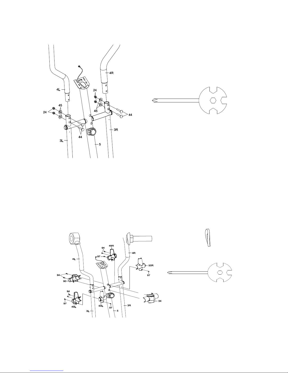
4. Left and Right Handrails Installation
Attach the Left/Right Handrails (4L, 4R) onto the Left/Right Handrail Arms (3L, 3R) with four
M6x35 Bolts (44), four Ø6 Curve Washers (45), and four M6 Nylon Nuts (24). Tighten
nylon nuts with the Multi Hex Tool with Phillips Screwdriver provided.
Hardware:
Tool:
Multi Hex Tool with Phillips Screwdriver
S10, S13, S14, S15
(44) Bolt M6x35
4 PCS
(45) Curve Washer Ø6
4 PCS
(24) Nylon Nut M6
4 PCS Tool
:
Multi Hex Tool with Phillips
Screwdriver
S10, S13, S14, S15
5. Left/Right Handrail Arm Covers-A/B and Front/Rear Decorative Covers for Front
Post Installation
Remove four ST4.2x20 Phillips Self Tapping Screws (97) from the Left/Right Handrail Arms
(3L, 3R). Remove screws with the Multi Hex Tool with Phillips Screwdriver provided.
Attach the Left Handrail Arm Cover-A (49L) and Left Handrail Arm Cover-B (50L) onto the
Left Handrail Arm (3L) with two ST4.2x12 Screws (94) and two ST4.2x20 Phillips Self
Tapping Screws (97) that were removed. Tighten screws with the Multi Hex Tool with
Phillips Screwdriver provided.
Attach the Right Handrail Arm Cover-A (49R) and Right Handrail Arm Cover-B (50R) onto
The Right Handrail Arm (3R) with two ST4.2x12 Screws (94) and two ST4.2x20 Phillips
Self
Tapping Screws (97) that were removed. Tighten screws with the Multi Hex Tool with
Phillips Screwdriver provided.
Attach the Rear Decorative Cover for Front Post (54) and Front Decorative Cover for Front
Post (90) onto the Front Post (5) with two ST4.2x12 Screws (94). Tighten screws with the
Multi Hex Tool with Phillips Screwdriver provided.
Hard are:
Tool:
Multi Hex Tool with Phillips Screwdriver
S10, S13, S14, S15
Allen Wrench S6
(94) Screw
ST4.2x12
6 PCS

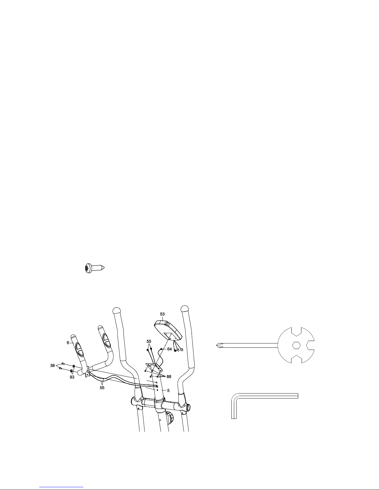
6. Handlebar and Computer Installation
Remove four M5x10 Bolts (88) from the back of the Computer (53). Remove bolts with the
Multi Hex Tool with Phillips Screwdriver provided.
Remove two M8x15 Bolts (38) and two Ø16xØ8 Curve Washers (93) from the Front Post
(5).
Remove bolts and curve washers with the S6 Allen Wrench provided.
Insert the Hand Pulse Sensor Wires (55) from the Handlebar (6) into the hole on the Front
Post (5) and then pull them out from the top end of the Front Post (5).
Attach the Handlebar (6) onto the Front Post (5) with two M8x15 Bolts (38) and two
Ø16xØ8
Curve Washers (93) that were removed. Tighten bolts and curve washers with the S6 Allen
Wrench provided.
Connect the Extension Sensor Wire (64) and Hand Pulse Sensor Wires (55) to the wires
that
come from the Computer (53) and then attach the Computer (53) onto the top end of the
Front Post (5) with four M5x10 Bolts (88) that were removed. Tighten bolts with the Multi
Hex Tool with Phillips Screwdriver provided.
OPERATING THE COMPUTER
SPECIFICATIONS:
TIME --------------------------------------------------- 0:00-99:59 MIN: SEC
SPD (SPEED) --------------------------------------- 0.0-99.9 KM/H
DIST (DISTANCE) --------------------------------- 0.0-999.9 KM
CAL (CALORIES) ---------------------------------- 0.0-999.9 KCAL
ODO (ODOMETER) ------------------------------- 0-9999 KM
PULSE ------------------------------------------------ 40-240 BEATS/MIN
USING YOUR COMPUTER
The computer can be activated by pressing the buttons or by pedaling. If you leave the
equipment for 4 minutes, the power will turn off automatically.
BUTTON FUNCTIONS:
MODE: Press the MODE button to select each function of the computer.
Press and hold the MODE button for 3 seconds to reset all data values to zero except the
ODO (ODOMETER) data values.

UP: Press the UP button to increase the data values of TIME, DISTANCE, CALORIES, or
PULSE for target pre-setting.
DOWN: Press the DOWN button to decrease the data values of TIME, DISTANCE,
CALORIES, or PULSE for target pre-setting.
RESET: Press the RESET button to clear data values of TIME, DISTANCE, or CALORIES
to
zero.
Press the RESET button to clear data values of TIME, DISTANCE, CALORIES, or PULSE
to
zero for target pre-setting.
Press and hold the RESET button for 3 seconds to reset all data values to zero except the
ODO (ODOMETER) data values.
COMPUTER FUNTIONS:
SCAN: Press the MODE button until the screen displays SCAN, the computer will
automatically scan each function in sequence with change every 6 seconds.
TIME: Displays your elapsed workout time in minutes and seconds. You may also pre-set
target time in STOP mode before training. To set TIME press the MODE button until you
see the TIME on the screen. Press the UP or DOWN button, TIME begins blinking. Press
the UP or DOWN button to change the time, each time you press the UP or DOWN button
TIME should change by 1 minute. Press the RESET button to clear the target time to zero.
The pre-set target time range is from 0:00 to 99:00 minutes. Once you pre-set target time
and then start to exercise, time starts counting down from pre-set target time to 0:00 per 1
second backward. When the pre-set target time counts down to 0:00, time will start to
count up immediately and the computer will begin beeping to remind you.
SPD (SPEED): Display the current training speed.
DIST (DISTANCE): Displays the accumulative distance traveled during workout. You may
also pre-set target distance in STOP mode before training. To set DISTANCE press the
MODE button until you see the DIST on the screen. Press the UP or DOWN button, DIST
begins blinking. Press the UP or DOWN button to change the distance, each time you
press the UP or DOWN button DISTANCE should change by 1.0 km. Press the RESET
button to clear the target distance to zero. The pre-set target distance range is from 0.0 to
999.0 km. Once you pre-set target distance and then start to exercise, distance starts
counting down from pre-set target distance to 0.0. When the pre-set target distance counts
down to 0.0, distance will start to count up immediately and the computer will begin beeping
to remind you.
CAL (CALORIES): Displays the total accumulated calories burned during workout. You
may also pre-set target calories in STOP mode before training. To set CALORIES press

the MODE button until you see the CAL on the screen. Press the UP or DOWN button,
CAL begins blinking. Press the UP or DOWN button to change the calories, each time you
press the UP or DOWN button CALORIES change by 1.0 calorie. Press the RESET button
to clear the target calories to zero. The pre-set target calories range is from 0.0 to 999.0
calories. Once you pre-set target calories and then start to exercise, calories start counting
down from pre-set target calories to 0.0. When the pre-set target calories count down to
0.0, calories will start to count up immediately and the computer will begin beeping to
remind
you. (This data is a rough guide for comparison of different exercise sessions and should
not be used in medical treatment).
ODO (ODOMETER): Displays the total accumulative distance traveled. The data values of
ODO can not be clear to zero by pressing and holding the MODE or RESET button for 3
seconds. If you take out the batteries from the computer, the ODO data values will clear to
zero.
PULSE: Displays your current heart rate figures after you grip the handlebar sensors with
both your hands during exercise. To ensure the pulse readout is more precise, please
always hold on to the handlebar grip sensors with two hands instead of just with one hand
only when you try to test your heart rate figures. You may also pre-set target heart rate in
STOP mode before training. To set PULSE press the MODE button until you see the
PULSE on the screen. Press the UP or DOWN button, target heart rate begins blinking.
Press the UP or DOWN button to pre-set target heart rate. Press the RESET button to
clear the target heart rate to zero. The pre-set heart rate range is from 40 to 240 beats per
minute. Once you pre-set target heart rate and then start to exercise, please grip the
handlebar sensors with both your hands during exercise. If the heart rate detected greater
than the target heart rate, the computer will begin beeping to remind you.
HOW TO INSTALL THE BATTERIES:
1. Remove the battery cover on the back of the computer.
2. Place two "SIZE-AA" batteries into the battery housing.
3. Insure batteries are correctly positioned and battery springs are proper contact with
batteries.
4. Re-install the battery cover.
5. If the display is illegible or only partial segment appear, remove batteries and wait 15
seconds before reinstalling.

ADJUSTMENTS
Adjusting the Tension Control Knob
To increase the load, turn the tension control knob in a
clockwise direction.
To decrease the load, turn the tension control knob in a
counterclockwise direction.
Adjusting the Adjustable Leveler
Turn the adjustable leveler on the rear stabilizer as needed to
level the elliptical trainer.
Adjustable Leveler
Tension Control Knob

MAINTENANCE
Cleaning
The elliptical trainer can be cleaned with a soft cloth and mild detergent. Do not use
abrasives or solvents on plastic parts. Please wipe your perspiration off the elliptical trainer
after each use. Be careful not get excessive moisture on the computer display panel as this
might cause an electrical hazard or electronics to fail.
Please keep the elliptical trainer, specially, the computer console, out of direct sunlight to
prevent screen damage.
Please inspect all assembly bolts and pedals on the machine for proper tightness every
week.
Storage
Store the elliptical trainer in a clean and dry environment away from children.
TROUBLESHOOTINGWARM UP AND COOL DOWN
PROBLEMv SOLUTION
The elliptical trainer wobbles when in use.
Vzpřímené kolo se netočí při používání
Vzpriamené kolo sa netočí při používaní
Turn the adjustable leveler on the rear stabilizer
as needed to level the elliptical trainer.
Otočte nastavitelný mostík so zadným stabilizátorom
podla potreby, aby sa vyrovnala vzpriamenost bicykla
There is no display on the computer
console.
Neexistuje žádnej display na počítačové
konsole
Neexistuje žiadna obrazovka na
počítačovej konzole
1. Remove the computer console and verify
the wires that come from the computer
console are properly connected to the
wires that come from the front post.
2. Check if the batteries are correctly
positioned and battery springs are in
proper contact with batteries.
3. The batteries in the computer console may
be dead. Change to new batteries.
1.Odstrante počítač z konzoli a ověvřete
dráty, které pocházejí z počítačové
konzoly.Zjistěte jestli jsou správně
připojené k drátům , které přicházejí ze
sloupu řidítek.
2. Zkontrolujte , zda jsou baterie správně
umístěny.
3.Mezi baterií a počítačem může bíti taky
zlý kontakt.
There is no heart rate reading or heart rate
reading or is erratic / inconsistent.
1. Make sure that the wire connections for
the hand pulse sensors are secure.
2. To ensure the pulse readout is more
precise, please always hold on to the
handlebar grip sensors with two hands
instead of just with one hand only when
you try to test your heart rate figures.
3. Gripping the hand pulse sensors too tight.
Table of contents
Other SPARTAN sport Elliptical Trainer manuals


Popular Elliptical Trainer manuals by other brands

NordicTrack
NordicTrack AudioStrider 990 PRO NTEL09811.2 user manual

Weslo
Weslo Momentum 4.0 Elliptical Manuale d'istruzioni

Progear Fitness
Progear Fitness Air elliptical pro 1307 owner's manual

Torque Fitness
Torque Fitness XPLLP owner's manual

Octane Fitness
Octane Fitness PRO3700C Operation manual

Xterra
Xterra FS5.8e owner's manual


