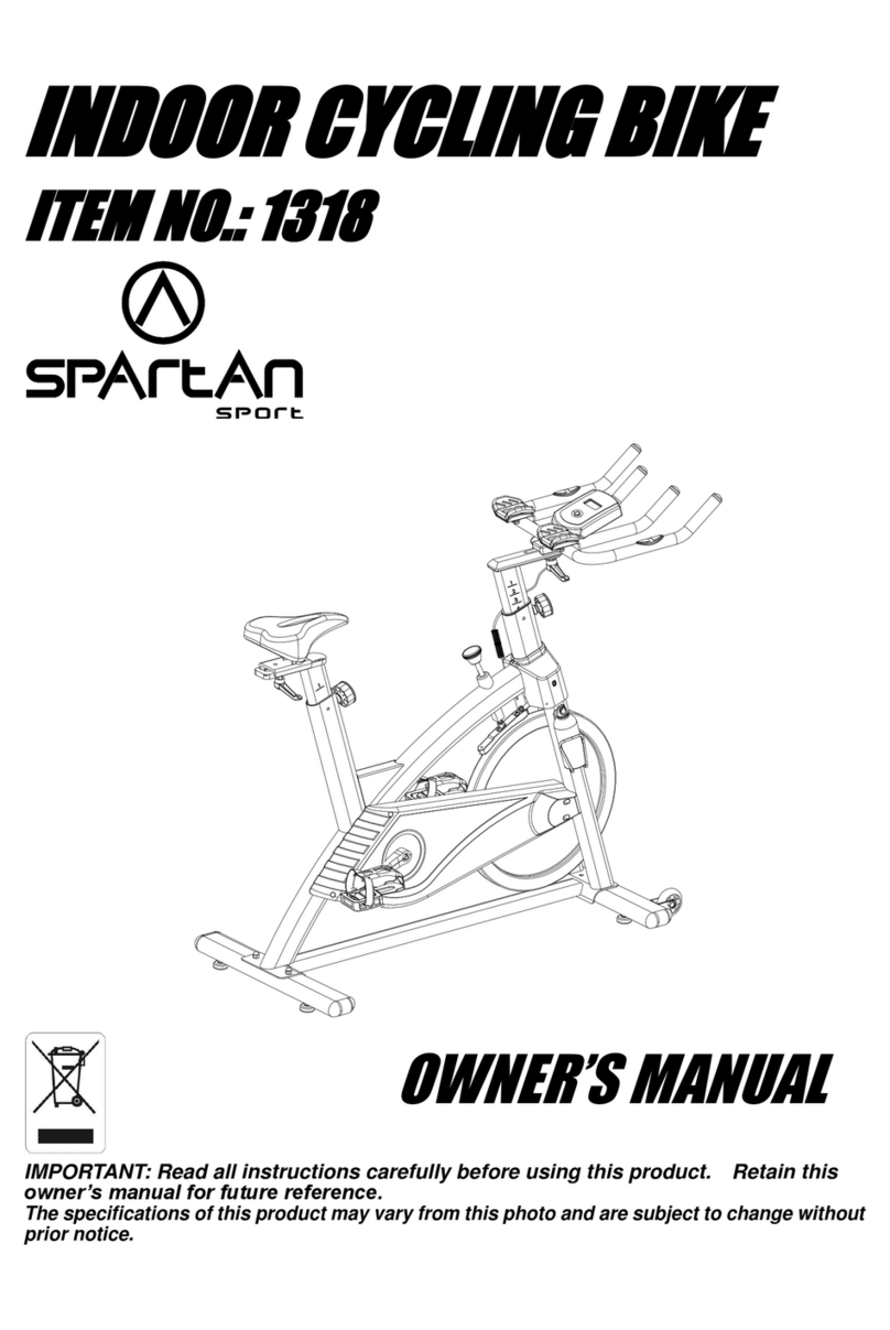
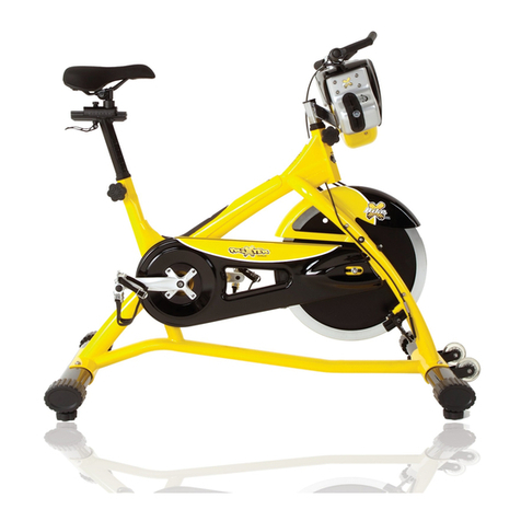
SPARTAN sport Magnetic 50 User manual

1
···
Owner’s Manual
Retain this owner’s manual for future reference
Read and follow all instructions in this owner’s manual
Version A


2
Thank you
Thank you so much for purchasing this product. The product will help you maintain
optimal aerobic fitness. To avoid personal injury, please read the following instructions
carefully before using this product. Please keep this manual for future reference.
Precautions
WARN NG: This upright bike has been designed and constructed to provide maximum
safety. Nevertheless, certain precautions should be taken when using exercise equipment.
Read the whole manual before assembling and using the upright bike. The following
safety precautions should also be observed:
◆t is the responsibility of the owner to ensure that all users of the upright bike are
adequately informed of all precautions. Use the upright bikes only as described in this
manual.
◆Keep children and pets away from this equipment at all times. Do not leave them
unsupervised in the room where place this upright bike.
◆Before using, please confirm that the upright bike has been assembled properly and
the screws in each part have been locked.
◆Place the upright bike on a level surface, with at least 1.0 m of clearance on each side
of upright bike. To protect the floor or carpet from damage, place a mat under the upright
bike.
◆Keep the upright bike indoors, away from moisture and dust. Keep the air flowing
when use it and do not use it in the airless place.
◆Don’t put any sharp objects around the upright bike.
◆Wear appropriate clothes while exercising; do not wear loose clothes that could
become caught on the upright bike. Always wear athletic shoes for foot protection while
exercising.
◆Do not use this product if more than 120kg of weights. Please choose our other series
of upright bikes.
◆Do not put your hands on the moving parts to prevent injures.
◆Keep your pedaling speed in a controlled way.
◆f you find your upright bike works abnormal, do not use it immediately.
◆No more than one person should operate the upright bike at one time.
◆f you feel pain or dizziness while exercising, stop exercising immediately and ask for
a doctor.

3
Safety notice
When you are remedial or have below symptoms, after discussing with your doctor, then
could use this upright bike.
1. Waist paining now and leg, waist, neck hurt before, legs, waist, neck and hand
numbly(The pre-existing disease people who suffer from intervertebral disc,
spondylosis, cervical spine, etc )
2. Have anamorphic arthritis, rheumatic and gout.
3. Have osteoporosis and other abnormality.
4. Have perfunctory system obstacle (heart disease, blood obstacle, hypertension ).
5. Have breath obstacle.
6. Using the manpower pulse adjust machine or insert into the body machine.
7. Have sarcomata.
8. Have thrombus or other symptoms.
9. Have diabetes or be caused by diabetes feeling obstacle.
10. Have skin trauma.
11. Hyperpyrexia caused by sick(38 ℃or over 38 ℃).
12. Abnormal back bone or back bone bending.
13. Pregnant or catamenia.
14. Feel physical abnormality, need convalesce.
15. Body condition is not very well.
16. The aim is to healing.
17. Except the upper symptoms, feel other physical abnormality.
----Maybe cause the accident or the poor body condition.
Before beginning any exercise program, consult your physician. This is especially
important for persons over age 35 or persons with pre-existing health problems. To
reduce the ris of serious injury, read all important precautions and instructions in
this manual and all warnings on your upright bi e before using your upright bi e.

4
Pre-assembly Notes
Make sure to the inventory all the parts that are included in the box. Check the
hardware chart of a full count of the number of parts included for proper
assembly. If any of the parts are missing, contact with the dealer.
Φ8.5×20(31)-7 Φ8.5×R25(33)-2Φ8(30)-7
M8(35)-2 ST4×16(36)-2 M4×10(39)-4
M5×10(38)-4
M8×20(32)-2M8×50(29)-4
M8×65(34)-3
NO. NAME SPECIFICATION QTY
29 Allen C.K.S. half thread screw M8×50×20 4
30 Spring washer Φ8 7
31 Flat washer Φ8.5×Φ20×t1.5 7
32 Allen C.K.S. full thread screw M8×20 2
33 Curved washer Φ8.5×R25×t2.0 2
34 Allen C.K.S. full thread screw M8×65×20 3

5
35 Hex self-locking nut M8 2
36 Philips C.K.S. self-tapping screw ST4×16 2
38 Philips pan head full thread screw M5×10 4
39 Philips pan head full thread screw M4×10 4
Toolkit list
GATHER YOUR TOO S
Before starting the assembly of your unit, gather the necessary tools. Having all the
equipment at hand will save time and make the assembly quick and hassle-free.
C EAR YOUR WORK AREA
Make sure that you have cleared away a large enough space to properly assemble the
unit. Make sure the space is free from anything that may cause injury during assembly.
After the unit is fully asssembled, make sure there is a comfortable amount of free area
around the unit for unabstructed operation.
Name Specification QTY
L Allen wrench 5×35×80S 1
L Allen wrench 6×40×120 1
Open spanner 15#&17# 1
Cross open wrench 1

6
Product instruction
Technical information
Dimension Unfold:1100x530x1400mm
Speed Ratio 8
Flywheel Single way,Φ280/6kg
Up & Down 12 level , 360mm distance
Front & Back 70mm distance
*WE RESERVE THE R GHT TO AMEND THE PRODUCT W THOUT PR OR NOT CE.
Console
Wheel
Front stabilizer
Pedal L
Rear stabilizer
Saddle
Bottle holder
Resistance adjustment knob
Handle bar
Pedal R

7
Step 1
Step 2
ASSEMBLY
INSTRUCTIONS
Attach the front stabilizer (2) to the main
frame (1) with flat washer (31), spring
washer (30) and Allen C.K.S. half thread
screw (29).
Attach the rear stabilizer (3) to the main
frame (1) with flat washer (31), spring
washer (30) and Allen C.K.S half thread
screw (29).

8
Step 3
1. Attach the Upright post decoration strip (46) to the upper right upright post (4), take
the down upright post cover (19) off from the main frame (1) and cover it on the upper
upright post (4).
2. Connect Magnetic sensor wire (12) and console communication wire (13), connect the
resistance adjust knob wire (14) and resistance adjust knob outlet (15).
3. Attach upper upright post (4) to the main frame(1) with curved washer( 33), spring
washer (30), Allen C.K.S. half thread screw (34) and flat washer (31), spring washer
(30), Allen C.K.S full thread screw (32) and flat washer ( 31), Allen C.K.S. half thread
screw (34), Hex self-locking nut (35), curve washer (33), spring washer (30) and
Allen C.K.S. full thread screw (32).
4. Attach upright post cover (19) and upright post decoration strip ( 46) to the main frame
(1).
5. Attach the bottle holder ( 20) to the upper upright post (4) with Phillips C.K.S. full
thread screw (36).
Tip: Put the communication wires and resistance adjust knob wire into the upright post,
and make sure all screws are in the hole before tighten all the bolts.

9
Attention:Hold and
pull up the brake cable
when install it. (As
shown)

10
Step 4
Step 5:
1. Attach the Pedal (L) (5) and Pedal (R)
(6) to the main frame (1), then tighten the
bolts.
1, Loose the Rotary hand bolt (21),
attach the Saddle post (7) to the main
frame (1), then tighten the Rotary hand
bolt
(21)
.

11
Step 6:
Step 7
7
4
38
38
10
9
26
16
Attach the saddle (8) to the saddle post (7), use the handlebar rotary knob ( 22) and
bushing (23) to tighten.
1. Handle pulse connection wire (16) through the upright post (4), and attach the
handlebars (9) to upright post (4), tighten with T-shaped rotary knob (26).
2. Attach console fixed piece (10) to the upright post (4), tighten with Philips Pan
head full thread screw(38).
Tip: Make sure all screws are in the right hole before tighten all the bolts.
6
8
23
7
21
22

12
Step 8
Workout tips
1. User need to put the feet completely inside the pedal, and to adjust the resistance of
magnet control according to the user.
2. Since the machine with double flywheels and it will have huge moment of inertia,
when the user stop before high speed, the user should minimize the resistance and
lower the speed, to avoid hurt the user’s leg by the moment of inertia of left and right
pedal.
3. The machine should be put on the flat floor and have enough space for workout.
1. Connect the console communication
wire (13) and console connection wire
(18), connect the handle pulse
connection wire (16) and console
pulse outlet wire(17).
2. Attach the console (11) to the console
fixed piece (10), tighten with Phillips
C.K.S full thread screw (40) and flat
washer (83).
3. Attach the handlebar cover L (27) and
handlebar cover R (28) through the
handlebars(9) to the upright post (4),
tighten with Philips C.K.S full thread
screw (39).
Tip: Make sure all screws are in the right
hole before tighten all the bolts.

13
Half-drawing for assembly
29
30
31
29
30
31
29
30
31
31 30 32
19
4
15
33
30
34
5
6
7
23
26
38
38
9
10
11
39
27
28
39
17
13
2
3
21
14
16
18
12
1
46
20
36
22
34
35
13
31
32
40
94
8

14
Half-drawing part list
NO. NAME SPECIFICATION QTY
1Main frame 1
2Front stabilizer 1
3Rear stabilizer 1
4Upright post 1
5Pedal L 1
6Pedal R 1
7Saddle post 1
8Saddle 1
9Handlebar 1
10 Console fixed piece 1
11 Console 1
12 Magnetic sensor wire 1
13 Console communication wire 1
14 Resistance adjust knob wire 1
15 Resistance adjust knob 1
16 Handle pulse connection wire 2
17 Console pulse outlet 2
18 Console connection wire 1
19 Down upright post cover 1
20 Bottle holder 1
21 Rotary hand bolt Φ56×M16×P1.5 1

15
22 Handlebar rotary knob 1
23 Bushing Φ10.5×Φ14×10 1
26 T-shaped rotary knob M8×30 1
27 Handlebar cover (L) 1
28 Handlebar cover (R) 1
29 Allen C.K.S. half thread screw M8×50×20 4
30 Spring washer Φ8 7
31 Flat washer Φ8.5×Φ20×t1.5 7
32 Allen C.K.S.full thread screw M8×20 2
33 Curve washer Φ8.5×R25×t2.0 2
34 Allen C.K.S. half thread screw M8×65×20 3
35 Hex self-locking nut M8 2
36 Philips C.K.S. self-tapping screw ST4×16 2
38 Philips pan head full thread screw M5×10 4
39 Philips pan head full thread screw M4×10 4
40 Philips pan head full thread screw M5×10(black) 4
46 Upright post decoration strip 1
83 Flat washer Φ4.5×Φ12×t1.0 4

16
Exploded drawing
65
51
85
32
35
64
51
66
63
35
73
75
76
62
62
63
63
67
69
68
70
72
52
74
84
31
58
47
48
48
2
50
49
47
51 31
30
29 30
29
31
86
29
30
31
29
30
31
3
31 30 32
4
33
30
34
38
38
39
27
28
39
17
18
15
46
19
81
44 81
81
88
89
43
43
44
36
36
36
36
6
7
23
26
80
79
87 87
16
12
13
14
35
51
54
53
56
78
1
59
45
9
21
81
20
36
22
90
93
92
82
55
36
91
31
34
35
32
11
10
40
83
77
77
35
31
8
71
61
57
42
41
42
41
5
37
25
24
60

17
Exploded part list
NO. NAME SPECIFICATION QTY
1Main frame 1
2Front stabilizer 1
3Rear stabilizer 1
4Upright post 1
5Pedal L 1
6Pedal R 1
7Saddle post 1
8Saddle 1
9Handlebar 1
10 Console fixed piece 1
11 Console 1
12 Magnetic sensor wire 1
13 Console communication wire 1
14 Resistance adjust knob wire 1
15 Resistance adjust knob 1
16 Handle pulse connection wire 2
17 Console pulse outlet 2
18 Console connection wire 1
19 Down upright post cover 1
20 Bottle holder 1
21 Rotary hand bolt Φ56×M16×P1.5 1
22 Handlebar rotary knob 1
23 Bushing Φ10.5×Φ14×10 1
24 Locknut t4.0×37×37 1
25 Check ring 1
26 T-shaped rotary knob M8×30 1
27 Handlebar cover (L) 1
28 Handlebar cover (R) 1
29 Allen C.K.S. half thread screw M8×50×20 4

18
30 Spring washer Φ8 7
31 Flat washer Φ8.5×Φ20×t1.5 8
32 Allen C.K.S.full thread screw M8×20 7
33 Curve washer Φ8.5×R25×t2.0 2
34 Allen C.K.S. half thread screw M8×65×20 3
35 Hex self-locking nut M8 9
36 Philips C.K.S. self-tapping screw ST4×16 8
37 Φ45×12 1
38 Philips pan head full thread screw M5×10 4
39 Philips pan head full thread screw M4×10 4
40 Philips pan head full thread screw M5×10 4
41 Crank L 1
42 Crank Φ55×16 2
43 Crank cover 2
44 Philips C.K.S. self-tapping screw ST4×12 4
45 Philips pan head half thread screw M5×55×20 1
46 Upright post decoration strip 1
47 End cap 4
48 Feet pad Φ47×10.5×M10×20 4
49 Allen C.K.S. hollow screw Φ8×33×M6×15 2
50 Wheels Φ55×25.8 2
51 Allen C.K.S.full thread screw M6×15 5
52 Deep groove ball bearing 6203-2RS 1
53 Hex nut M5 2
54 Hex full thread screw M5×80 1
55 Philips C.K.S. self-tapping screw ST4×12 1
56 Saddle post bushing 1
57 Crank co er Φ45×12 1
58 Belt puller Φ263×19 1
59 Flat washer Φ5 1
60 Saddle adjustment 1
61 Washer t3.0×Φ40×Φ24.3 1
Top ring

19
62 Circlip shaft Φ12 2
63 Circlip shaft Φ10 3
64 Tension pulley Φ38×22 1
65 Tension spring 1
66 Brake tension spring 1
67 Deep groove ball bearing 6003-2RS 3
68 Magnetic control fixed axle Φ12×50 1
69 Deep groove ball bearing 6300-2RS 1
70 Flat washer Φ34×Φ25×t1.0 1
71 Crank axle 6.5’’ 1
72 Unidirectional needle bearing Φ35×Φ17×16 1
73 Small belt pulley set Φ30×64 1
74 Deep groove ball bearing 6000-2RS 1
75 Flywheel axle Φ10×109.5 1
76 Flywheel Φ280/6kg 1
77 Sqaure end cap 20×40×t1.5 1
78 Handle pulse set 2
79 Philips C.K.S. self-tapping screw ST4×20 2
80 Round end cap Φ25×t1.5 2
81 Philips C.K.S. self-tapping screw ST4×25 7
82 Fixed magnetic set 1
83 Flat washer Φ4.5×Φ12×t1.0 4
84 Tension pulley fixed set 1
85 Magnetic control set 1
86 Motor belt 440PJ6 1
87 Foam Φ22×t3.0×680 2
88 Motor cover L 1
89 Motor cover R 1
90 Saddle locking piece 1
91 Speed sensor fixed piece 1
92 Allen C.K.S. full thread screw M10×38 1
93 Elastic washer Φ10 1
This manual suits for next models
1
Table of contents
Other SPARTAN sport Exercise Bike manuals
Popular Exercise Bike manuals by other brands

Sunny Health & Fitness
Sunny Health & Fitness SF-B121021 user manual

Monark
Monark 827E instruction manual

Stamina
Stamina 1310 owner's manual

American Fitness
American Fitness SPR-BK1072A owner's manual

Cateye
Cateye CS-1000 (CYCLO SIMULATOR) Service manual

BH FITNESS
BH FITNESS H9158H Instructions for assembly and use


