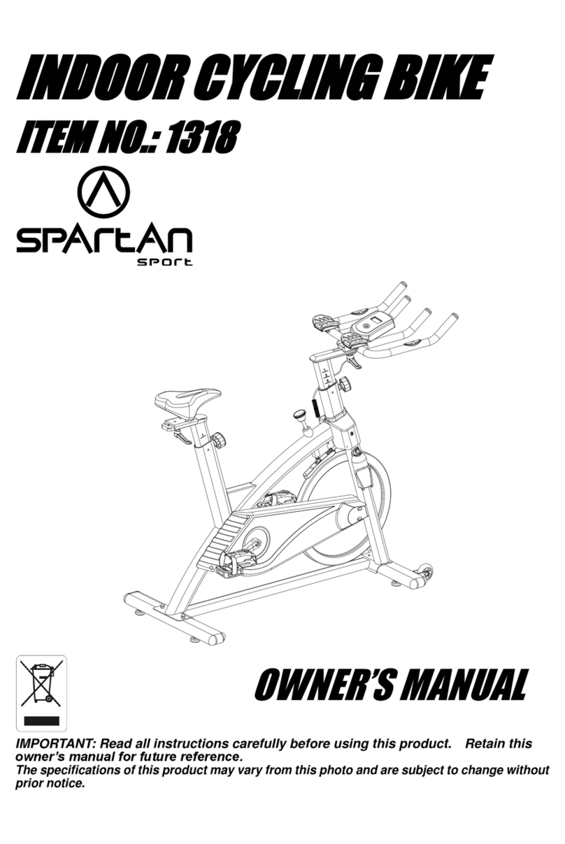
SPARTAN sport 1113 User manual

INDOOR CYCLING BIKE
ITEM NO.: 1113
OWNER’S MANUAL
IMPORTANT: Read all instructions carefully before using this product. Retain this
owner’s manual for future reference.
The specifications of this product may vary from this photo and are subject to change without
prior notice.

1
TABLE OF CONTENTS
IMPORTANT SAFETY INSTRUCTIONS ------------------------------------------- 2
PARTS LIST ------------------------------------------------------------------------------- 4
HARDWARE PACKING LIST --------------------------------------------------------- 5
TOOLS -------------------------------------------------------------------------------------- 5
OVERVIEW DRAWING ----------------------------------------------------------------- 6
ASSEMBLY INSTRUCTIONS --------------------------------------------------------- 7
OPERATING THE COMPUTER ------------------------------------------------------ 13
ADJUSTMENTS -------------------------------------------------------------------------- 15
EMERGENCY STOP -------------------------------------------------------------------- 17
MOVING THE SPINNER BIKE ------------------------------------------------------- 17
MAINTENANCE -------------------------------------------------------------------------- 18
TROUBLESHOOTING ------------------------------------------------------------------ 18
WARM UP AND COOL DOWN ROUTINE ----------------------------------------- 20

2
IMPORTANT SAFETY INSTRUCTIONS
Basic precautions should always be followed, including the following important
safety instructions when using this equipment. Read all instructions before using
this equipment.
1. Read all instructions and follow it carefully before using this equipment. Make sure the
equipment is properly assembled and tightened before use.
2. Before exercise, in order to avoid injuring the muscle, warm-up exercises are
recommended.
3. Please make sure all parts are not damaged and fixed well before use. This
equipment should be placed on a flat surface when using. Using a mat or other
covering material on the ground is recommended.
4. Please wear proper clothes and shoes when using this equipment; do not use the
spinner bike barefoot, in only socks or in sandals, always wear athletic shoes. Never
wear loose clothing that may catch any part of the equipment.
5. Do not attempt any maintenance or adjustments other than those described in this
manual. Should any problems arise, discontinue use and consult your local dealer.
6. Never insert any object into any opening.
7. Always hold on to the handlebar while using this equipment.
8. Do not use the equipment outdoors.
9. This equipment is for household use only. It is not a commercial model.
10. Only one person at a time should use this equipment.
11. If you feel any chest pains, nausea, dizziness, or short of breath, you should stop
exercising immediately and consult your physician before continuing.
12. Care should be taken in mounting or dismounting the equipment.
13. Do not allow children to use or play on the equipment. Keep children and pets away
from the equipment while in use. This machine is designed for adults use only. The
minimum free space required for safe operation is not less than two meters.
14. The maximum weight capacity for this product is 110 kgs.
Wichtige Sicherheitsanleitungen:
1. Lessen Sie vor dem Gebrauch die Anleitung genau durch. Überzeigen Sie sich,daß
das Gerät richtig zusammengebaut ist und alle Schrauben angezogen sind.
2. Wärmen Sie sich vor dem Training auf, damit Verletzungen vermieden werden.
3. Das Gerät muß beim Trainieren auf einem ebenen Untergrund stehen. Es wird
empfohlen eine Matte unterzulegen.
4. Immer richtige Sportbekleidung tragen , niemals barfuß trainieren. Nicht mit zu locker
sitzender Kleidung trainieren.
5. Keine Veränderungen am Gerät vornehmen außer denen, die hier beschrieben sind.
Sollten irgendwelche Probleme auftauchen, kontaktieren Sie Ihren Händler.
6. Niemals irgendwelche Objekte in irgendwelche Öffnungen werfen.

3
7. Halten Sie die Handgriffe beim Training immer fest
8. Niemals im Freien verwenden
9. Das Gerät ist nicht für den kommerziellen Gebrauch geeignet, nur für den
Heimgberauch
10. Nur 1 Person kann trainieren, niemals 2 gleichzeitig
11. Sollten Sie sich nicht gut fühlen, brechen Sie das Training sofort ab und konsultieren
Sie Ihren Arzt
12. Das Gerät muß sorgfältig auf-und abgebaut werden
13. Kinder sollten sich vom Gerät fern halten und nicht damit spielen, es ist nur für
ERwachsene geeignet. Man braucht ca 2 Meter rundherum Platz um ein richtiges,
sicheres Training durchzuführen
14. Maximales Benützergewicht ist 110 kg
WARNING: Before beginning any exercise program consult your physician.
This is especially important for the people who are over 35 years old or who have
pre-existing health problems. Read all instructions before using any fitness
equipment.
Achtung: vor dem Training Ihren Arzt konsultieren. Das ist speziell wichtig für
Menschen über 35 JAhre und/oder mit gesundheitlichen Problemen. Vor dem
Gebrauch die ANleitung lesen.
CAUTION: Read all instructions carefully before operating this product.
Retain this Owner’s Manual for future reference.
No.
Description Qty
No.
Description Qty

4
PARTS LIST
PARTS LIST
001 Front Stabilizer End Cap Ø60 2 030 Nut M10 2
002 Bolt M8x40 2 031 Washer Ø10 2
003 Washer Ø8 8 032 Sleeve Ø16xØ10.3x25 1
004 Transport Wheel Ø36xØ9x20 2 033 Bearing (6000) 2
005 Front Stabilizer Ø60x480 1 034 Flywheel Axle (Ø10x132) 1
006 Nylon Nut M8 2 035 Flywheel Disk Ø387x2.3 2
007 Bolt M8x70 4 036 Flywheel (Ø453) 1
008 Handlebar Foam Grip
Ø33xØ23x475 2 037 Screw ST4.2x18 7
009 Handlebar 1 038 Round Knob M16x1.5 2
010 Handlebar End Cap Ø25.4x1.5 2 039 Locking Knob M8 1
011 Bolt M8x12 4 040 Brake Block 19x19x10 1
012 Plastic Bushing 2 041 Cap Nut Ø16x19 1
013 Handlebar Post 1 042 Spring Plate 100x15.5x1.5 1
014 Handlebar Post End Cap
53.5x23.5x1.5 1 043 Small Spring Plate 30x15.5x2 1
015 Saddle DD2022 1 044 Bolt M6x12 2
016 Saddle Sliding Tube End Cap
30x30x1.5 2 045 Nut M5 1
017 Square Nut 24x24x12 1 046 Bolt M5x8 1
018 Seat Post 1 047 Brake Plate 140x25x13 1
019 Sleeve Ø14xØ10x30 1 048 Washer Ø5 6
020 Saddle Adjustment Knob M10x70
1 049 Bolt M5x20 1
021 Brake Knob Ø50x23 1 050 Bolt M5x12 1
022 Brake Knob Rod Ø10x225 1 051 Cap Nut M8 4
023 Brake Knob Rod Sleeve
Ø15.1x100 1 052 Curve Washer Ø8 4
024 Main Frame 1 053 Pan Head Phillips Self Drilling
Screw ST4.2x19 8
025 Cap Nut M10 2 054 Rectangular Cover Plate 66x23x2
2
026 Eyebolt M6 2 055 Bolt M5x15 6
027 Round Nut M6 2 056 Saddle Sliding Tube 1
028 Nut M6 2 057 Left Cover BC413-048-001 1
029 Spring Washer Ø10 2 058 Crank Cover BC194-801-003 2
No.
Description Qty
No.
Description Qty

5
HARDWARE PACKING LIST
TOOLS
OVERVIEW DRAWING
059
Left Foot Pedal BC410-1000-022L
1 074
Water Bottle Holder
B410-1000-030 1
060
Crank Nut 7/8" 1 075
Brake Pad 140x26x6 1
061
Washer 7/8" 1 076
Screw ST3.5x8 2
062
Slotted Bearing Nut 7/8" 1 077
Nut M8 2
063
Bearing 15/16" 2 078
Screw ST4.2x19 3
064
Bearing Cup Ø56 2 079
Sensor Bracket 1
065
Notched Bearing Nut 15/16" 1 080
Sensor Wire L=800 1
066
Washer 15/16" 1 081
Wire Plug 4
067
Crank with Pulley Ø200X2.5 1 082
Hand Pulse Sensor 2
068
Right Cover BC413-048-001 1 083
Hand Pulse Sensor Wire L=630 1
069
Right Foot Pedal
BC410-1000-022R 1 084
Nut M4 1
070
Chain 1 085
Screw M4x30 1
071
Rear Stabilizer End Cap Ø60 2 086
Computer Bracket 1
072
Rear Stabilizer Ø60x480 1 087
Computer (LT8817) 1
073
Water Bottle B410-1000-040 1
(3) Washer Ø8
4 PCS
(7) Bolt M8x70
4 PCS
(11) Bolt M8x12
4 PCS
(51) Cap Nut M8
4 PCS
(52) Curve Washer Ø8
4 PCS
Allen Wrench 6mm
1 PC
Multi Hex Tool with Phillips Screwdriver
S13, S14, S15
1
PC

6
ASSEMBLY INSTRUCTIONS

7
1. Rear Stabilizer Installation
Position the Rear Stabilizer (72) behind the Main Frame (24) and align bolt holes.
Attach the Rear Stabilizer (72) onto the rear curve of the Main Frame (24) with two M8x70
Bolts (7), two M8 Cap Nuts (51), and two Ø8 Curve Washers (52). Tighten cap nuts with
the Multi Hex Tool with Phillips Screwdriver provided.
Hardware:
Tool:
:
Multi Hex Tool with Phillips Screwdriver
S13, S14, S15
(7) Bolt M8x70
2 PCS
(51) Cap Nut M8
2 PCS
(52) Curve Washer Ø8
2 PCS

8
2. Front Stabilizer Installation
Position the Front Stabilizer (5) in front of Main Frame (24) and align bolt holes.
Attach the Front Stabilizer (5) onto the front curve of the Main Frame (24) with two M8x70
Bolts (7), two M8 Cap Nuts (51), and two Ø8 Curve Washers (52). Tighten cap nuts with
the Multi Hex Tool with Phillips Screwdriver provided.
Hardware:
Tool:
:
Multi Hex Tool with Phillips Screwdriver
S13, S14, S15
(7) Bolt M8x70
2 PCS
(51) Cap Nut M8
2 PCS
(52) Curve Washer Ø8
2 PCS

9
3. Saddle Installation
Loosen both M8 Nuts (77) from underneath of the Saddle (15) with the Multi Hex Tool with
Phillips Screwdriver provided. Then install the Saddle (15) onto the Saddle Sliding Tube
(56) and secure with both M8 Nuts (77) that were loosened. Tighten both M8 Nuts (77) with
the Multi Hex Tool with Phillips Screwdriver provided.
․․․․․․․․․․․․․․․․․․․․․․․․․․․․․․․․․․․․․․․
4. Handlebar Installation
Attach the Handlebar (9) onto the Handlebar Post (13) with four Ø8 Washers (3) and four
M8x12 Bolts (11). Tighten bolts with the Allen Wrench provided.
Tool:
:
Multi Hex Tool with Phillips Screwdriver
S13, S14, S15
Allen Wrench 6mm
Tool:
:
Hardware:
:
(3) Washer Ø8
4 PCS
(11) Bolt M8x12
4 PCS

10
5. Handlebar Post Installation
Release the Locking Knob (39) and then loosen the Round Knob (38) by turning
counterclockwise direction until it can be pulled out. Pull out the Round Knob (38) and then
insert the Handlebar Post (13) into the Plastic Bushing (12) on the tube of the Main Frame
(24). Slide the Handlebar Post (13) up or down direction to the suitable position. Lock the
Handlebar Post (13) in place by releasing the Round Knob (38) and sliding the Handlebar
Post (13) up or down slightly until the Round Knob (38) "pops" down into the locked position.
For added safety, tighten the Locking Knob (39) and Round Knob (38) in a clockwise
direction.
NOTE: When adjusting the height of Handlebar Post (13), the STOP line cannot higher
than the edge of Plastic Bushing (12).

11
6. Computer and Computer Bracket Installation
Remove one M4 Nut (84) and one M4x30 Screw (85) from the Computer Bracket (86).
Remove screw and nut with the Multi Hex Tool with Phillips Screwdriver provided.
Attach the Computer Bracket (86) onto the Handlebar (9) with one M4 Nut (84) and one
M4x30 Screw (85) that were removed. Tighten screw and nut with the Multi Hex Tool with
Phillips Screwdriver provided.
Slide the Computer (87) onto the Computer Bracket (86) until it locks into place.
Connect the Sensor Wire (80) from the Main Frame (24) to the wire that comes from the
Computer (87).
Plug the Hand Pulse Sensor Wire (83) into receptacle located on the back of the Computer
(87).
Tool:
:
Multi Hex Tool with Phillips Screwdriver
S13, S14, S15

12
7. Left and Right Foot Pedals Installation
The Pedal Shafts, Cranks, and Foot Pedals are marked “R” for Right and “L” for Left.
Insert the pedal shaft of Left Foot Pedal (59) into threaded hole in the left Crank (67). Turn
the pedal shaft by hand in the counterclockwise direction until snug.
Note: DO NOT turn the pedal shaft in the clockwise direction, doing so will strip the
threads.
Tighten the pedal shaft of Left Foot Pedal (59) with the Multi Hex Tool with Phillips
Screwdriver provided.
Insert pedal shaft of Right Foot Pedal (69) into threaded hole in right Crank (67). Turn the
pedal shaft by hand in the clockwise direction until snug.
Tighten pedal shaft of Right Foot Pedal (69) with the Multi Hex Tool with Phillips Screwdriver
provided.
Die Pedale sind mit “R” für rechts und “L” für links markiert. Drehen Sie entgegen dem
Uhrzeigersinn um die Pedale zu befestigen. Ziehen Sie die Scraube dann mit dem
Schraubenschlüssel fest.
Tool:
:
Multi Hex Tool with Phillips Screwdriver
S13, S14, S15

13
OPERATING THE COMPUTER
SPECIFICATIONS:
TIME --------------------------------------------------- 0:00-99:59 MIN: SEC
SPEED ------------------------------------------------ 0.0-99 KM/H
DISTANCE ------------------------------------------- 0.0-999.9 KM
CALORIES ------------------------------------------- 0.0-9999 KCAL
PULSE ------------------------------------------------ 40-240 BEATS/MIN
USING YOUR COMPUTER
The computer can be activated by pressing the MODE button or by pedaling. If you leave
the equipment idle for 4-5 minutes, the power will turn off automatically.
Der Computer wird aktiviert indem man die MODE Taste drückt oder zu treten beginnt.
4-5 Minuten nachdem Sie aufgehört haben zu trainieren, schaltet sich der Computer
automatisch ab.
BUTTON FUNCTIONS:
MODE: Press the MODE button to select each function of computer.
Press and hold the MODE button for 3 seconds to reset all data values to zero.
Mit der MODE Tste können Sie die Funktionen wählen, wenn Sie sie 3 Sekunden
halten, werden alle DAten auf 0 gestellt.
COMPUTER FUNTIONS:
SCAN: Automatically scans each function in sequence.
Scant automatisch durch alle Funktionen
TIME: Displays your elapsed workout time in minutes and seconds.
Zeigt die Trainingszeit in Minuten und Sekunden
SPEED: Displays the current training speed.
Zeigt die Trainingsgeschwindigkeit
DISTANCE: Displays the cumulative distance traveled during workout.
Zeigt die zurückgelegte Distanz
CALORIES: Displays approximate amount of calories burned during workout.
(This data is a rough guide for comparison of different exercise sessions and should not be
used in medical treatment).
Zeigt die während des Trainings verbrauchten KAlorien. (diese DAten sind nicht für
medizinische Zwecke geeignet)
PULSE: Displays your current heart rate figures after you grip the handlebar pulse sensors
with both your hands during exercise. To ensure the pulse readout is more precise, please

14
always hold on to the handlebar pulse sensors with both hands instead of just with one hand
when you try to test your heart rate figures.
Zeigt Ihre Herzfrequenz wenn Sie die Sensoren mit beiden Händen fest halten, um die
Genauigkeit zu erhöhen, bitte immer mit beiden Händen halten
HOW TO INSTALL THE BATTERIES:
1. Remove the battery cover on the back of the computer.
2. Place two size AA batteries into the battery housing.
3. Insure batteries are correctly positioned and battery springs are in proper contact with
batteries.
4. Re-install the battery cover.
5. If the display is illegible or only partial segment appears, remove batteries and wait 15
seconds before reinstalling.
1. Entfernen Sie die Batteriehülle an der Rückseite des Computers
2. Geben Sie 2 Stk. AA BAtterien hinein
3. Überzeugen Sie sich, daß die Batterien korrekt installiert sind und richtigen Kontakt
mit den Federn haben
4. Geben Sie die Hülle wieder hinauf
5. Wenn das display nicht lesbar ist, entfernen Sie die BAtterien noch einmal und legen
Sie sie nach 15 Sekunden wieder ein

15
Brake Knob
Round Knob
Locking Knob
ADJUSTMENTS
Adjusting the Rear Stabilizer End Cap
Turn the Rear Stabilizer End Cap on the rear stabilizer as needed to level the bike.
Drehen Sie die Endkappe so wie Sie es benötigen um das Rad gerade zu stellen
Adjusting the Brake Knob
To increase the tension, turn the Brake Knob in a clockwise direction.
To decrease the tension, turn the Brake Knob in a counterclockwise direction.
Adjusting the Handlebar Height
Release the Locking Knob and then loosen the Round Knob by turning counterclockwise
direction until it can be pulled out. Pull out the Round Knob and then slide the Handlebar
Post up or down direction to the suitable position. Lock the Handlebar Post in place by
releasing the Round Knob and sliding the Handlebar Post up or down slightly until the Round
Knob "pops" down into the locked position. For added safety, tighten the Locking Knob and
Round Knob in a clockwise direction.
NOTE: When adjusting the height of handlebar, the STOP line cannot higher than the
edge of plastic bushing.
Rear Stabilizer End Cap

16
Adjusting the Saddle Height
Loosen the Round Knob by turning counterclockwise direction until it can be pulled out.
Pull out the Round Knob and then slide the Seat Post up or down direction to the suitable
position. Lock the Seat Post in place by releasing the Round Knob and sliding the Seat
Post up or down slightly until the Round Knob "pops" down into the locked position. For
added safety, tighten the Round Knob in a clockwise direction.
NOTE: When adjusting the height of seat post, the STOP line cannot higher than the
edge of plastic bushing.
Adjusting the Saddle Forward or Back
Loosen the Saddle Adjustment Knob by turning counterclockwise direction. Slide the
Saddle Sliding Tube forth or back direction to the suitable position. Lock the Saddle Sliding
Tube in place by turning clockwise direction.
Öffenen Sie den Knopf für die Sattelbefestigung indem Sie gegen den Uhrzeigersinn drehen.
Befestigen Sie ihn dann am richtigen Platz indem Sie im Uhrzeigersinn drehen
Saddle Adjustment Knob
Round Knob

17
EMERGENCY STOP
To emergency stop, press firmly down onto the BRAKE KNOB. Continue holding the
BRAKE KNOB down until the flywheel comes to a complete stop.
Eine Notbremsung können Sie machen indem Sie den Notbremsknopf drücken und halten
MOVING THE SPINNER BIKE
Start by carefully pushing down on the handlebar until the rear end of the bike lifts in the air.
Carefully push the bike to the desired location.
Drücken Sie das Gerät vorne nach unten bis sich der Hinterteil in die Höhe bewegt, dann können Sie
das Rad bewegen

18
MAINTENANCE
Cleaning
The spinner bike can be cleaned with a soft clean damp cloth. Do not use abrasives or
solvents on plastic parts. Please wipe your perspiration off the spinner bike after each use.
Be careful not to get excessive moisture on the computer display panel as this might cause
an electrical hazard or electronics to fail.
Please keep the spinner bike, especially the computer console out of direct sunlight to
prevent screen damage.
Please inspect all assembly bolts, nuts, screws, and pedals on the machine for proper
tightness every week.
Sie können das Gerät mit einem sauberen, trockenen Tuch reinigen. Keine Putzmittel an
den Plastikteilen verwenden. Wichen Sie den Schweiß nach jedem Gebrauch weg. Der
Computer soll nicht naß werden. Die Computerkonsole soll nicht dem direkten Sonnenlicht
ausgestzt sein. Die Schrauben sind regelmäßig zu überprüfen ob sie festgezogen sind
Storage
Store the spinner bike in a clean and dry environment away from children.
An einem trockenem , sauberem Ort aufbewahren, nicht in der reichweite von Kindern
TROUBLESHOOTING
PROBLEM SOLUTION
The bike wobbles when in use.
Das Rad wackelt beim Training
Turn the rear stabilizer end cap on the rear
stabilizer as needed to level the bike.
Drehen Sie die Endkappen am hinteren
Stabilisator um Ungleichheiten auszugleichen
There is no display on the computer
console.
Der Computer zeigt nichts an
1. Remove the computer console and verify
the wire that comes from the computer
console is properly connected to the wire
that comes from the main frame.
Überprüfen Sie ob das Computerkabel
richtig mit dem KAbel vom HAuptrahmen
verbunden ist
2. Check if the batteries are correctly
positioned and battery springs are in
proper contact with batteries.
Überprüfen Sie ob die Batterien richtig
eingelegt sind
3. The batteries in the computer console
may
be dead. Replace with new batteries.
Wenn die BAtterien leer sind, müssen sie
ersetzt werden

19
There is no heart-rate reading or there is
erratic / inconsistent reading.
Die Herzfrequenz wird schlecht oder nicht
angezeigt
1. Make sure that the hand pulse wire is
properly plugged into receptacle located
on the back of the computer.
Überprüfen Sie ob das Handpulskabel
richtig hinten am Computer eingesteckt
wurde
2. To ensure the pulse readout is more
precise, please always hold on to the
handlebar grip sensors with both hands
instead of just with one hand when you try
to test your heart rate figures.
Um die Genauigkeit zu erhöhen, halten
Sie die Griffsensoren mit beiden Händen
3. Avoid gripping the hand pulse sensors too
tight. Try to maintain moderate pressure
while holding onto the hand pulse sensors
halten Sie die Sensoren nicht zu fest.
The bike makes a squeaking noise when in
use.
Das Gerät macht Lärm wenn Sie trainieren
The bolts may be loose on the bike. Please
inspect all of the bolts and tighten any loose
bolts.
Alle Schrauben müssen kontrolliert und
nachgezogen werden
Table of contents
Other SPARTAN sport Exercise Bike manuals
