SPARTAN sport Magnetic 800 User manual

Magnetic 800
Magnetic Upright Bike
ITEM NO.: 1002N
OWNER’S MANUAL
IMPORTANT: Read all instructions carefully before using this product. Retain this
owner’s manual for future reference.
The specifications of this product may vary from this photo and are subject to change without
prior notice.

1
TABLE OF CONTENTS
IMPORTANT SAFETY INSTRUCTIONS ------------------------------------------- 2
PARTS LIST ------------------------------------------------------------------------------- 3
HARDWARE LIST ----------------------------------------------------------------------- 5
TOOLS -------------------------------------------------------------------------------------- 5
EXPLODED VIEW ----------------------------------------------------------------------- 6
ASSEMBLY INSTRUCTIONS --------------------------------------------------------- 7
OPERATING THE COMPUTER ------------------------------------------------------ 18
HOW TO MOVE THE BIKE ------------------------------------------------------------20
MAINTENANCE -------------------------------------------------------------------------- 20
ADJUSTMENTS -------------------------------------------------------------------------- 21
TROUBLESHOOTING ------------------------------------------------------------------ 22
WARM UP AND COOL DOWN ROUTINE ----------------------------------------- 23

2
IMPORTANT SAFETY INSTRUCTIONS
Basic precautions should always be followed, including the following important
safety instructions when using this equipment. Read all instructions before using
this equipment.
1. Read all instructions and follow it carefully before using this equipment. Make sure the
equipment is properly assembled and tightened before use.
2. Before exercise, in order to avoid injuring the muscle, warm-up exercises are
recommended.
3. Please make sure all parts are not damaged and fixed well before use. This
equipment should be placed on a flat surface when using. Using a mat or other
covering material on the ground is recommended.
4. Please wear proper clothes and shoes when using this equipment; do not wear clothes
that may catch any part of the equipment; remember to tighten the pedaling straps.
5. Do not attempt any maintenance or adjustments other than those described in this
manual. Should any problems arise, discontinue use and consult your local dealer.
6. Do not use the equipment outdoors.
7. This equipment is for household use only. It is not a commercial model.
8. Only one person at a time should use this equipment.
9. If you feel any chest pains, nausea, dizziness, or short of breath, you should stop
exercising immediately and consult your physician before continuing.
10. Care should be taken in mounting or dismounting the equipment.
11. Do not allow children to use or play on the equipment. Keep children and pets away
from the equipment while in use. This machine is designed for adults use only. The
minimum free space required for safe operation is not less than two meters.
12. The maximum weight capacity for this product is 110 kg.
WARNING: Before beginning any exercise program consult your
physician. This is especially important for people who are over 35 years old or who
have pre-existing health problems. Read all instructions before using any fitness
equipment. Do not operate this exercise equipment without properly fitted guards,
as the moving parts can present a risk of serious injury if exposed.
CAUTION:Read all instructions carefully before operating this product.
Retain this Owner’s Manual for future reference.

3
PARTS LIST
No.
Description
Qty
No.
Description
Qty
001
Main Frame
1
024
Cross Recessed Pan Head
Tapping Screw ST4.2x20
4
002
Front Stabilizer Ø60x1.5tx380
1
025
Cross Recessed Pan Head
Tapping Screw ST4.2x25
8
003
Rear Stabilizer Ø60x1.5tx480
1
026
Cross Recessed Pan Head
Drilling Screw with Tapping Screw
Thread ST4.2x25
4
004
Idler Arm
1
027
Nylon Nut M8
3
005
Seat Post
1
028
Nut M6
2
006
Seat Sliding Tube
1
029
Nut M10x6t
2
007
Handlebar Post
1
030
Cap Nut M8
2
008
Handlebar Ø25
1
031
Flywheel Ø230x40
1
009
Tension Bracket
2
032
Bearing Cup
2
010
Washer Ø8xØ16x1.5t
7
033
Ball Bearing
2
011
Cross Recessed Pan Head
Tapping Screw ST2.9x16
1
034
Bearing Nut I 15/16”
1
012
Front Left Stabilizer End Cap Ø60
1
035
Bearing Nut II 7/8”
1
013
Front Right Stabilizer End Cap
Ø60
1
036
Washer Ø24xØ40x3t
1
014
Curve Washer Ø8xØ20x1.5t
4
037
Washer Ø23xØ34.5x2.5t
1
015
Seat Adjustment Knob M10
1
038
Hexagon Nut 7/8”
1
016
Spring Washer Ø6
2
039
Belt Pulley with Crank
1
017
Carriage Bolt M8x70
2
040
Cross Recessed Pan Head Bolt
M5x20
1
018
Square End Cap □38
2
041
Washer Ø5xØ15x1.0t
1
019
Hexagon Socket Pan Head Cap
Bolt M8x15
2
042
Cross Recessed Pan Head Bolt
M5x10
4
020
Hexagon Socket Pan Head Cap
Bolt M8x30
1
043
Handlebar Foam Grip
Ø24xØ30x490
2
021
Eyebolt M6x36
2
044
Left Foot Pedal YH-30X
1
022
Bearing 60002Z
2
045
Right Foot Pedal YH-30X
1
023
Cross Recessed Pan Head
Tapping Screw ST2.9x12
2
046
Handlebar End Cap Ø25
2

4
PARTS LIST
No.
Description
Qty
No.
Description
Qty
047
Cover Cap Ø40xØ25x10
2
062
Computer
1
048
Seat Post Knob M16x1.5
1
063
Extension Sensor Wire
L=950 mm
1
049
Hand Pulse Sensor with Wire
L=750 mm
2
064
Handlebar T-Knob (M8x55)
1
050
Sensor with Wire L=750 mm
1
065
Washer Ø12xØ6x1t
1
051
Left Cover
1
066
Cross Recessed Pan Head Bolt
M6x10
1
052
Right Cover
1
067
Wire Grommet Ø12.1
1
053
Seat Post Plastic Bushing
1
068
Seat Sliding Tube Bolt
1
054
Tension Control Knob
1
069
Washer Ø8xØ20x2t
1
055
Tension Cable L=1150 mm
1
070
Hexagon Socket Pan Head Cap
Bolt M8x10
3
056
Clamp Cover
1
071
Rear Left Stabilizer End Cap Ø60
1
057
Spacer (Ø12x20)
1
072
Rear Right Stabilizer End Cap Ø60
1
058
Handlebar Post Cover
1
073
Hexagon Nut M10x6t
2
059
Seat Post Cover
1
074
Adjustable Leveler M10
2
060
Belt PJ370 J6
1
075
Hexagon Socket Pan Head Cap
Bolt M8x70
2
061
Seat Cushion (DD-982AT)
1
076
Washer Ø14xØ10xδ1.0
2

5
HARDWARE LIST
TOOLS
(14) Curve Washer
4 PCS
(17) Carriage Bolt
2 PCS
(30) Cap Nut
2 PCS
(75) Hexagon Socket
Pan Head Cap Bolt
2 PCS
Multi Hex Tool
1 PC
Multi Hex Tool with Phillips Screwdriver
1 PC
Allen Wrench S6
1 PC

6
EXPLODED VIEW

7
ASSEMBLY INSTRUCTIONS
STEP 1
Position the Front Stabilizer (2) in front of the Main Frame (1) and align bolt holes.
Attach the Front Stabilizer (2) onto the front curve plate of the Main Frame (1) with two Cap
Nuts (30), two Curve Washers (14), and two Carriage Bolts (17). Tighten cap nuts with
the Multi Hex Tool provided with Phillips Screwdriver.
Hardware:
(14) Curve Washer
2 PCS
(17) Carriage Bolt
2 PCS
(30) Cap Nut
2 PCS

8
STEP 2
Install two Adjustable Levelers (74) with two Hexagon Nuts (73) onto the Rear Stabilizer
(74).
Position the Rear Stabilizer (3) behind the Main Frame (1) and align bolt holes.
Attach the Rear Stabilizer (3) onto the rear curve of the Main Frame (1) with two Hexagon
Socket Pan Head Cap Bolts (75) and two Curve Washers (14). Tighten bolts with the
Allen Wrench provided.
Hardware:
(75) Hexagon Socket
Pan Head Cap Bolt
2 PCS
(14) Curve Washer
2 PCS
9
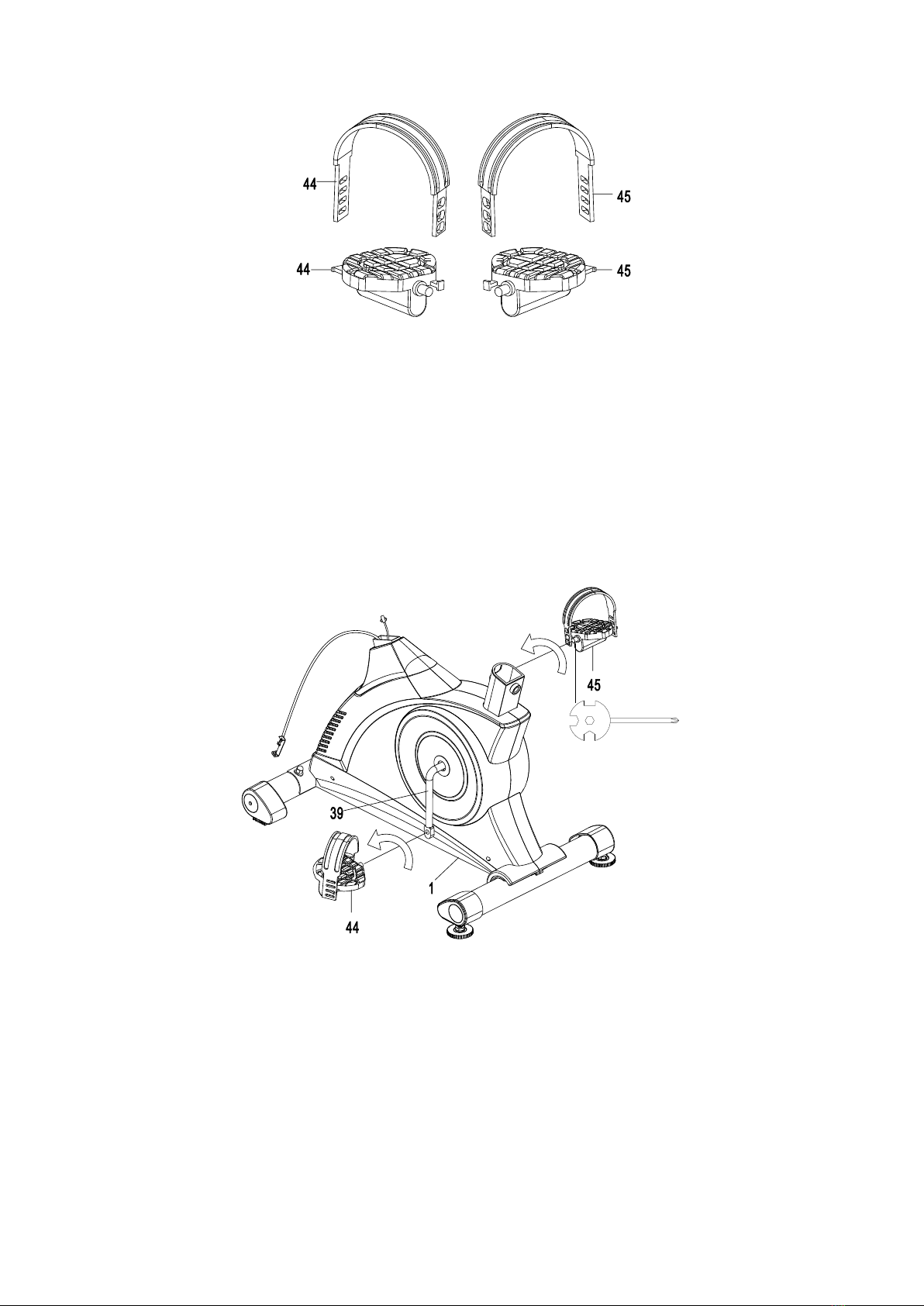
STEP 3
The Foot Pedals and Pedal Straps are marked “R” for Right and “L” for Left.
Select the Left Foot Pedal Strap (44) which has L marked on the side of the strap. Snap
the three hole end of the strap onto the inside edge of the Left Foot Pedal (44). Snap the
other end of the strap onto the outside edge of the Left Foot Pedal (44). Select adjustment
holes which allow your foot to be easily removed from the foot pedal.
Use the same procedure to snap the Right Foot Pedal Strap (45) onto the Right Foot Pedal
(45).
STEP 4
Insert the pedal shaft of Left Foot Pedal (44) into threaded hole in the left Crank (39). Turn
the pedal shaft by hand in the counter-clockwise direction until snug.
Note: DO NOT turn the pedal shaft in the clockwise direction, doing so will strip the
threads.
Tighten the pedal shaft of Left Foot Pedal (44) with the Multi Hex Tool with Phillips
Screwdriver provided.
Insert pedal shaft of Right Foot Pedal (45) into threaded hole in right Crank (39).Turn the
pedal shaft by hand in the clockwise direction until snug. Tighten pedal shaft of Right Foot
Pedal (45) with the Multi Hex Tool with Phillips Screwdriver provided.
10
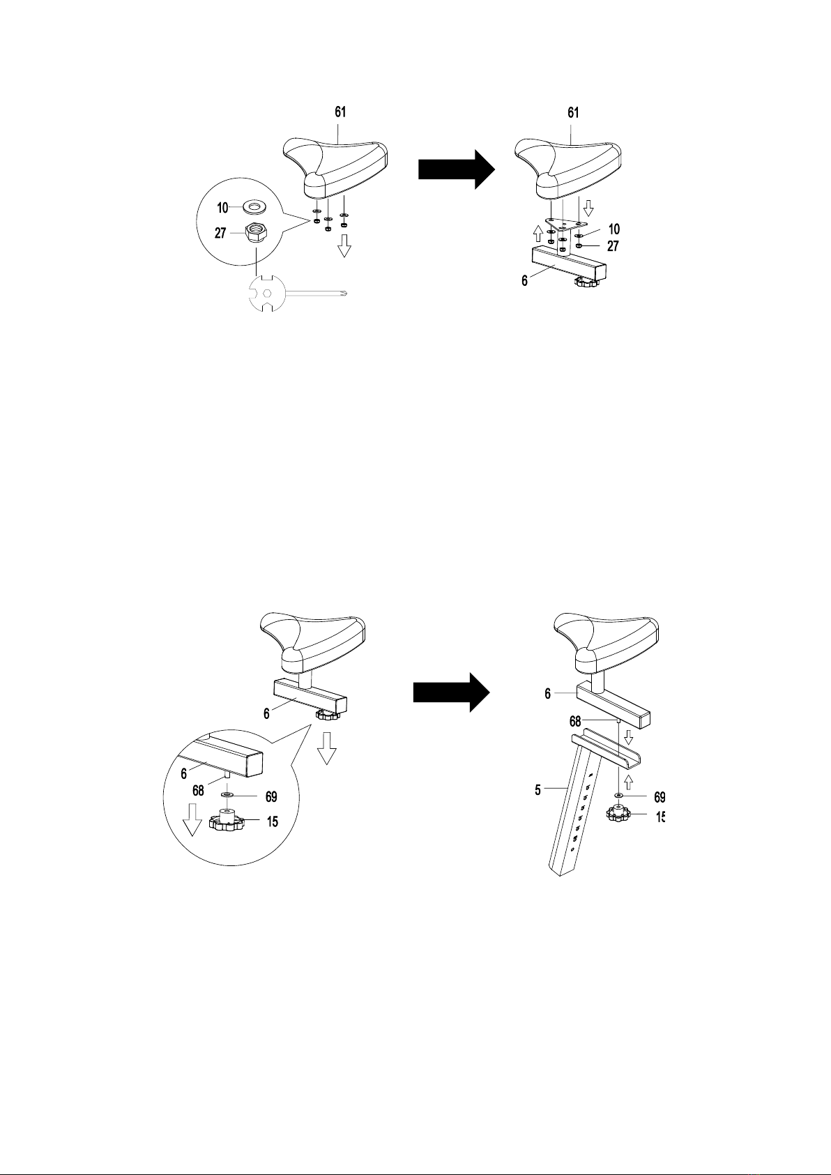
STEP 5
Remove three Nylon Nuts (27) and three Washers (10) from underside of the Seat Cushion
(61). Remove nylon nuts with the Multi Hex Tool with Phillips Screwdriver provided.
Guide bolts on underside of the Seat Cushion (61) through holes on top of the Seat Sliding
Tube (6), attach with three removed Nylon Nuts (27) and Washers (10). Tighten nylon
nuts with the Multi Hex Tool with Phillips Screwdriver provided.
STEP 6
Remove one Washer (69) and one Seat Adjustment Knob (15) from underside of the Seat
Sliding Tube (6).
Guide the Seat Sliding Tube Bolt (68) on underside of the Seat Sliding Tube (6) through a
hole on the top of the Seat Post (5), attach with one removed Washer (69) and Seat
Adjustment Knob (15).

11
STEP 7
Slide the Seat Post Cover (59) onto the tube of the Main Frame (1).
STEP 8
Insert the Seat Post (5) into the seat post plastic bushing on the tube of the Main Frame (1)
and then attach the Seat Post Knob (48) onto the tube of the Main Frame (1) by turning it in a
clockwise direction with Multi Hex Tool provided to lock the Seat Post (5) in the suitable
position.

12
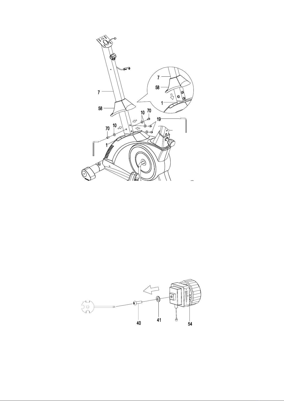
STEP 9
Remove the Handlebar Post Cover (58) from the Main Frame (1).
Remove two Hexagon Socket Pan Head Cap Bolts (19), two Hexagon Socket Pan Head
Cap Bolts (70), and four Washers (10) from the tube of the Main Frame (1). Remove bolts
with the Allen Wrench provided.
STEP 10
Slide the Handlebar Post Cover (58) up to the Handlebar Post (7).
13
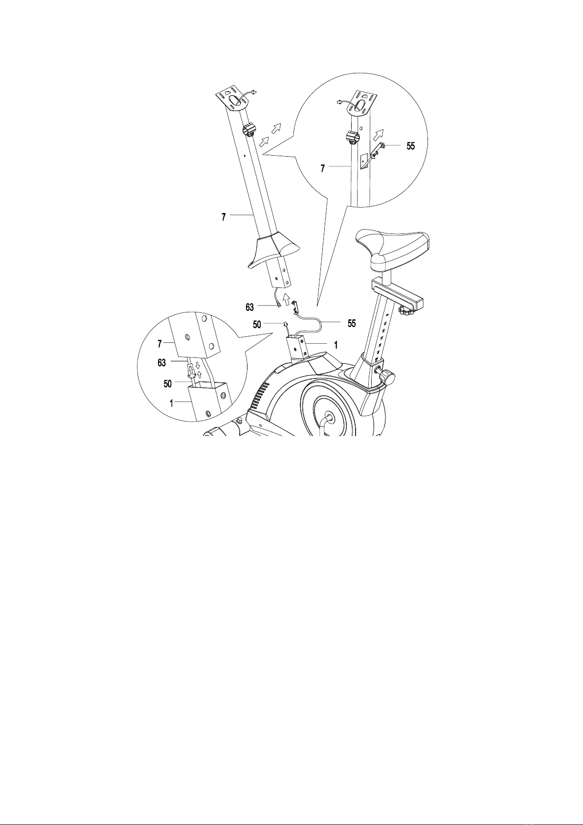
STEP 11
It is recommended to have a second person assist with this step. One person should hold
the Handlebar Post (7) in place while the other person to insert and connect the wires.
A. Insert the Tension Cable (55) through into the bottom hole of the Handlebar Post (7) and
pull it out from the square hole of the Handlebar Post (7).
B. Connect the Sensor Wire (50) from the Main Frame (1) to the Extension Sensor Wire
(63) from the Handlebar Post (7).
A.
B.
14
STEP 12
Insert the Handlebar Post (7) onto the tube of the Main Frame (1) and align bolt holes.
Attach the Handlebar Post (7) onto the tube of the Main Frame (1) with two Hexagon Socket
Pan Head Cap Bolts (19), two Hexagon Socket Pan Head Cap Bolts (70), and four Washers
(10) from the tube of the Main Frame (1) that were removed. Tighten bolts with the Allen
Wrench provided.
STEP 13
Remove one Cross Recessed Pan Head Bolt (40) and one Washer (41) from the Tension
Control Knob (54). Remove bolts with the Multi Hex Tool with Phillips Screwdriver
provided.

15
STEP 14
Put the cable end of resistance cable of Tension Control Knob (54) into the cable lock of
Tension Cable (55), see Figure A.
Pull the resistance cable of Tension Control Knob (54) up and force it into the slot of metal
bracket of Tension Cable (55), see Figure B.
Insert the metal fitting on the resistance cable of Tension Control Knob (54) into the hole at
the end of the slot in the metal bracket of Tension Cable (55), see Figure C.
Connect the resistance cable of Tension Control Knob (54) to Tension Cable (55) complete,
see Figure D.
Attach the Tension Control Knob (54) onto the Handlebar Post (7) with one Cross Recessed
Pan Head Bolt (40) and one Washer (41) that were removed. Tighten bolt with the Multi
Hex Tool with Phillips Screwdriver provided.
16
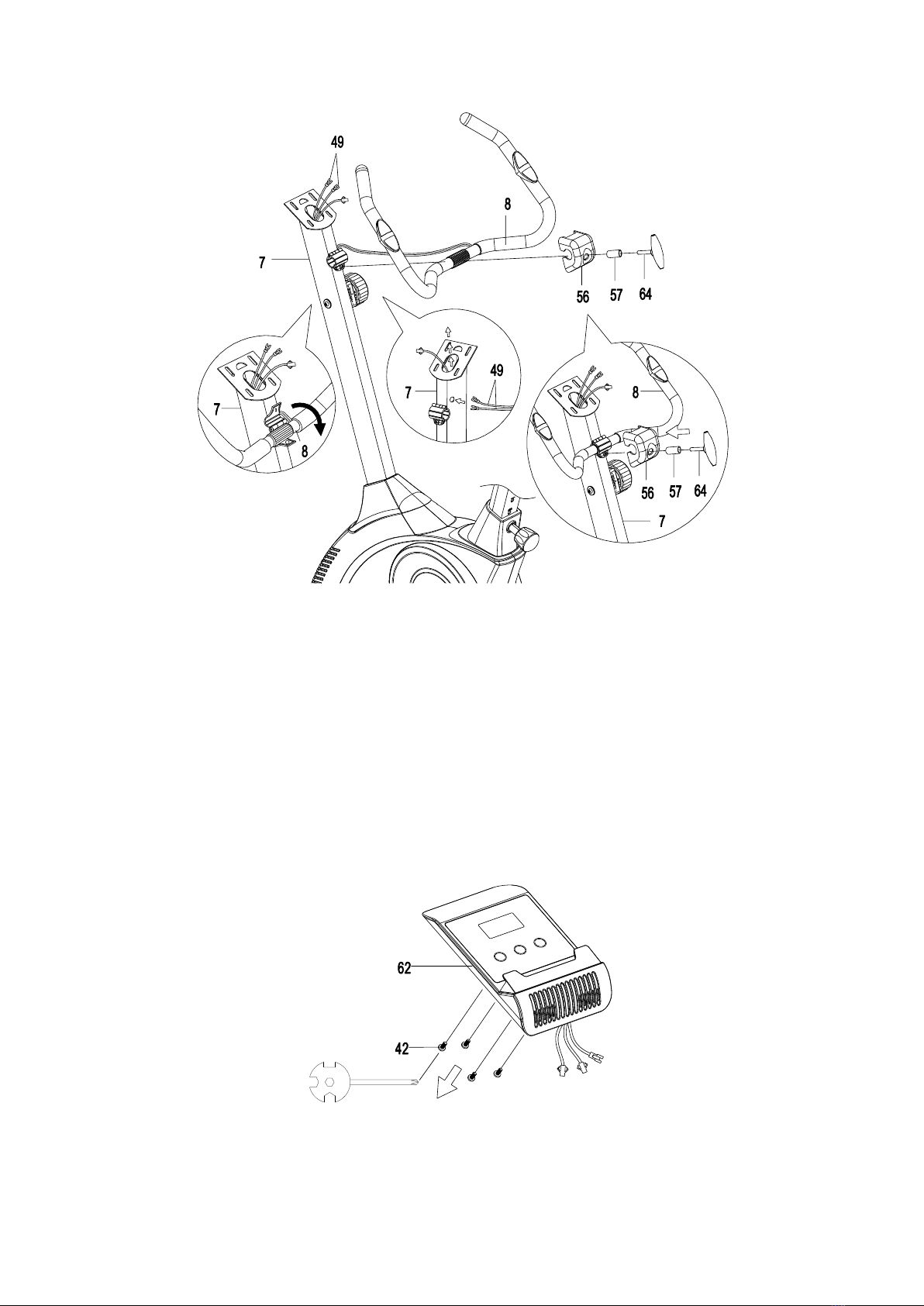
STEP 15
A. Insert the Hand Pulse Sensor Wires (49) through into the hole on the Handlebar Post (7)
and pull them out from the top end of the Handlebar Post (7).
B. Place the Handlebar (8) through clamp on the Handlebar Post (7) with hand pulse
sensors facing the seat.
C. Hold the Handlebar (8) in desired position and fasten Clamp Cover (56), Spacer (57),
and Handlebar T-Knob (64) onto clamp. Tighten the Handlebar T-Knob (64) after
adjustment.
NOTE: Handlebar T-Knob should be tightly secured before using.
STEP 16
Remove four Cross Recessed Pan Head Bolts (42) from the Computer (62). Remove bolts
with the Multi Hex Tool with Phillips Screwdriver provided.
A.
B.
C.
17
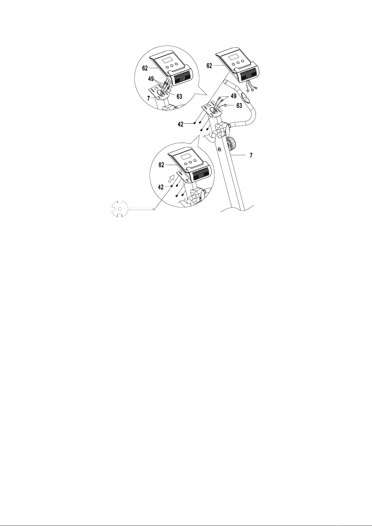
STEP 17
It is recommended to have a second person assist with this step. One person should hold
the Computer (62) in place while the other person to connect the wires.
Connect the Extension Sensor Wire (63) and Hand Pulse Sensor Wires (49) to the wires that
come from the Computer (62).
Tuck wires into the Handlebar Post (7) and then attach the Computer (62) onto the top end
of the Handlebar Post (7) with four Cross Recessed Pan Head Bolts (42) that were removed.
Tighten bolts with the Multi Hex Tool with Phillips Screwdriver provided.

18
OPERATING THE COMPUTER
USING YOUR COMPUTER
The computer can be activated by pressing one of the three buttons or by pedaling. If you
leave the equipment idle for 4 minutes, the power will turn off automatically.
BUTTON FUNCTIONS:
MODE: Press the MODE button to select the functions of the computer.
Press and hold the MODE button for 3 seconds to reset all data values to zero except the
ODO (ODOMETER) data values.
SET:Press the SET button to set data values of TIME, DIST (DISTANCE), CAL
(CALORIES), or PULSE for target pre-setting.
RESET: Press the RESET button to reset data values of TIME, DIST (DISTANCE), or CAL
(CALORIES) to zero.
Press the RESET button to reset data values of TIME, DIST (DISTANCE), CAL (CALORIES),
or PULSE to zero for target pre-setting.
COMPUTER FUNCTIONS:
SCAN: Press the MODE button until the screen displays SCAN, the computer will
automatically scan each function in sequence with change every 6 seconds.
TIME: Displays your elapsed workout time in minutes and seconds.
You may also pre-set target time in STOP mode before training. To set TIME press the
MODE button until the screen displays TIME. Press the SET button to change the time,
each time you press the SET button time should change by 1 minute. Press the RESET
button to clear the target time to zero. The pre-set target time range is from 0:00 to 99:00
minutes. Once you pre-set target time and then start to exercise, time starts counting down
from pre-set target time to 0:00 per 1 second backward. When the pre-set target time
counts down to 0:00, time will start to count up immediately and the computer will begin
beeping to remind you.
SPEED: Displays the current training speed.

19
DIST (DISTANCE): Displays the cumulative distance travelled during workout.
You may also pre-set target distance in STOP mode before training. To set DISTANCE
press the MODE button until the screen displays DIST. Press the SET button to change the
distance. Press the RESET button to clear the target distance to zero. The pre-set target
distance range is from 0.00 to 99.50 km.. Once you pre-set target distance and then start
to exercise, distance starts counting down from pre-set target distance to 0.00. When the
pre-set target distance counts down to 0.00, distance will start to count up immediately and
the computer will begin beeping to remind you.
CAL (CALORIES): Displays approximate amount of calories burned during workout.
You may also pre-set target calories in STOP mode before training. To set CALORIES
press the MODE button until the screen displays CAL. Press the SET button to change the
calories. Press the RESET button to clear the target calories to zero. The pre-set target
calories range is from 0.0 to 999.0 calories. Once you pre-set target calories and then start
to exercise, calories start counting down from pre-set target calories to 0.0. When the
pre-set target calories count down to 0.0, calories will start to count up immediately and the
computer will begin beeping to remind you. (This data is a rough guide for comparison of
different exercise sessions and should not be used in medical treatment).
ODO (ODOMETER): Displays the total accumulative distance travelled. The ODOMETER
data values can not be reset to zero by pressing and holding the MODE or RESET button for
3 seconds. If you take out the batteries from the computer, the ODOMETER data values
will reset to zero.
(PULSE): Displays your current heart rate figures after you grip the handlebar sensors
with both your hands during exercise. To ensure the pulse read-out is more precise, please
always hold on to the handlebar grip sensors with two hands instead of only one hand when
testing your heart rate figures. You may also pre-set target heart rate in STOP mode before
training. To set PULSE press the MODE button until the screen displays symbol.
Press the SET button to pre-set target heart rate. Press the RESET button to clear the
target heart rate to zero. Once you pre-set a target heart rate and then start to exercise,
please grip the handlebar sensors with both your hands during exercise. If the heart rate
detected is greater than the target heart rate, the computer will begin beeping to alert you.
HOW TO INSTALL THE BATTERIES:
1. Remove the battery cover on the back of the computer.
2. Place two size AA batteries into the battery housing.
3. Insure batteries are correctly positioned and battery springs are in proper contact with
batteries.
4. Re-install the battery cover.
5. If the display is illegible or only partial segment appears, remove batteries and wait 15
seconds before reinstalling.
Table of contents
Other SPARTAN sport Exercise Bike manuals


Popular Exercise Bike manuals by other brands

NordicTrack
NordicTrack NTEX08011.1 user manual

Weslo
Weslo Pursuit S 25 Exercise Bike Manuel de l'utilisateur
ICON Health & Fitness
ICON Health & Fitness PRO-FORM Le tour de france PFEX01915.1 user manual

Sunny Health & Fitness
Sunny Health & Fitness SF-B1805 user manual

Gymstick
Gymstick PRO FTR user manual

Life Gear
Life Gear 20460A owner's manual

Kettler
Kettler Cycle R Assembly instructions

Unisen
Unisen StarTrac E-Spinner Replacement instructions

Custo Med
Custo Med Ergometer ec3000 operating instructions

BH
BH H9168E Instructions for assembly and use

Horizon Fitness
Horizon Fitness M4 Service manual

NordicTrack
NordicTrack GX 4.5 NTEX03912.0 user manual


