6
2.1 EXAMPLE OF IDENTIFICATION PLATE
Safety Information Informations Sur La Sécurité
Listed by / Manufactured by:
Spartherm Feuerungstechnik GmbH
Maschweg 38
D – 49324 Melle, Germany
Listée par / Fabriqué par:
Spartherm Feuerungstechnik GmbH
Maschweg 38
D – 49324 Melle, Germany
Appareil de Chauffage a combustion solides
Tested aux Normes: UL-1482-11, ULC-S627-00,
U.S. Enviroment Protection Agency: Certified to comply with 2020
Particulate emission standards using cord wood
Model: Spartherm Cassette 600 Module
Date de Fabrication:
Mois/Année: 11/2019
No de Serie: Stove-600
Solid Fuel Room Heater – For Use with Solid Wood Fuel only
Tested toStandards: UL-1482-11, ULC-S627-00,
U.S. Enviroment Protection Agency: Certified to comply with 2020
Particulate emission standards using cord wood
Model: Spartherm Cassette 600 Module
Date of Manufacture
Month/Year:11/2019
Serial Number Stove-600
TO PREVENT HOUSE FIRES:
Contact local building or fire officials about restrictions and installation
inspection in your area. Install and use only in accordance with manufacturer’s
installation and operating instructions and local codes. In the absence of any local
codes, installation must meet minimum requirements of NFPA 211 in the USA, and
B365 in Canada. Refer to manufacturer´s instructions and local codes for
precautions required for passing a chimney through a combustible wall orceiling.
Inspect and clean chimney system frequently in accordance with manufacturer´s
instruction. Do not connect this stove to a chimney flue serving another appliance.
Do not use grate or elevate fire. Build wood fire directly on hearth. Installation only
with listed UL-103 HTor ULC S 629 chimney diameter 6 or 7 inches.
TO PREVENT CREOSOTE FIRES:
Inspect and clean chimney frequently - under certain conditions of use,creosote
buildup may occurrapidly. Do not use fuels other than firewood.
CAUTION:Only operate the wood heater with the doors fully closed. Replace
glass only with original 4 mm Robax ceramic glass. Areas of the fireplace
incorporating warm or cold air ducts shall be enclosed in accordance with the
manufacturer’s installation instructions. Ifprovided with a hearth extension, the
hearth extension must be installed according to the installation instructions! Air is
needed for fireplace operation! Atleast 14 square inches (90.3 square centimeters)
of outside air must be admitted to the room or directly to the unit through a 5”
(127mm) diameter pipe. Failure to provide this may starve other fuel burning
appliances from an adequate air supply. Do not obstruct air inlet and outlet in any
case. Components used with fireplace must be listed. See manual.
Do not use a fireplace insert or other products not specified for use with this
product.
CAUTION: Gas logs shall be certified for the application. This unit is not designed
to burn with a log set.
This wood heater needs periodic inspection and repair for proper operation.
Consult the owner’s manual for further information. Itisagainst federal regulations
to operate this wood heater in a manner inconsistent with the operating instructions
in the owner’s manual.
POUR EVITER LES INCENDIES DOMESTIQUES:
Contactez les Autorités des bâtiments et les pompiers pour obtenir des instructions concernant les
restrictions et inspections d´installation dans votre région. Installez et utillisez cet appareil
uniquement en respectant les instructions d´installation et d´utilisation du fabriquant. Respectez
également les réglementations locales. En l´absence de réglementations locales, l´installation doit
respecter les normes minimales de NFPA 211 aux Etats-Unis et B365 au Canada. Référez-vous
aux instructions du fabriquant aux réglementations locales pour obtenir des instructions
concernant les précautions nécessaires pour le passage de la cheminée á travers une paroi ou un
plafond combustible. Inspectez et nettoyez le système de cheminée fréquement selon les
instructions du fabriquant. Ne connectez pas ce poêle à un conduit de cheminée utilisé par un
autre appareil. N´utilisez pas de grille et ne faites pas monter le feu. Etablissez le feu de bois
directement dans l´âtre. L'installation doit être faite exclusivement avec le cheminée listé selon la
norue ULC-S604, ULC-S610 ou UL-103 HT de diaméte 6” / 7”.
POUR EVITER LES FEUX DE CREOSOTE : Inspectez et nettoyez la cheminée régulièrement -
Sous certaines condition d´emploi, la creosote peut s´accumuler rapidement. Ne pas utiliser
d´autres combustibles que le bois.
ATTENTION: N'utilisez le poêle que lorsque les portes sont complétement fermées. Remplacer
la vitre uniquement avec du verre Robax céramique de 4 mm.Il faut que les zones du foyer vitré
qui portent les canaux d'alimentation d'air chaud et froid soient conformes à l'instruction de
montage du fabricant. L'approvisionnement en revêtement fait de matériaux ininflammables
devant l'ouverture du foyer vitré doit être installé conforme a l'instruction de montage du fabricant.
L'aération suffisante pour l'utilisation du foyer est nécessaire! Dans l'emplacement du foyer vitré il
faut assurer au moins 14 pouces carée (90,3 centimètres carée) de l'air de dehors ou il faut assurer
l'alimentation en air de combustion directe au foyer vitré par une tube d'un diamètre de 5 pouces
carée ( 127mm). Un manque d’air d’appoint pourrait priver les autres apparells de combustion
d’une alimentation d’air adéquate. Ne pas obstruer les entrés et sorties d’air en aucun cas. Les
composantes utilisées dans l’appareil doivent étre répertoriées. Voir manuel. N'utilisez pas d'insert
de cheminée ou autres produits qui ne sont pas autorisés pour l'usage de ce produit.
ATTENTION: Ce poêle à bois n'est pas conçu pour brûler avec un bûche à gaz.
Ce foyer vitré à bois doit être entretenu et réparé à intervalles réguliers pour assurer un
fonctionnement correct. Veuillez consulter s.v.p. pour de plus amples informations les instructions
du fabricant. Il est contraire aux dispositons de l'autorité d'exploiter ce foyer vitré à bois incompatible
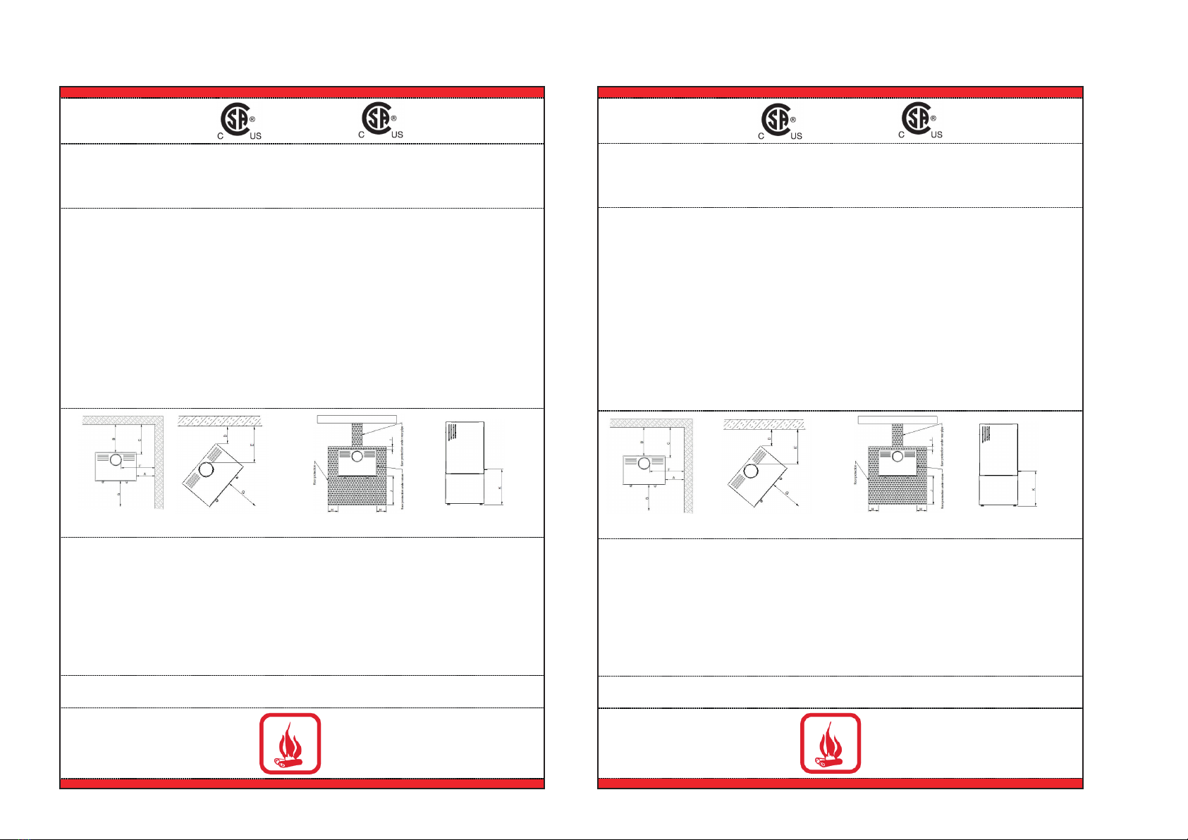
MINIMUM CLEARANCES TO COMBUSTIBLE MATERIALS
Single-wall connector pipe
11” / 279mm
Double-wall connector pipe
11” / 279mm
G.
H.
I.
J.
48” / 1219mm
For Canada 8” / 203mm
For USA 6” / 152mm
8” / 203mm
For Canada 18” / 450mm
For USA 16” / 406mm
48” / 1219mm
For Canada 8” / 203mm
For USA 6” / 152mm
8” / 203mm
For Canada 18” / 450mm
For USA 16” / 406mm
IN FRONT OF UNIT *
Recommend amount of wood:
1,8 kg/hr
ECARTEMENT MINIMUM AUX MATERIAUX COMBUSTIBLES
paroi simple
double paroi
G.
H.
I.
J.
48” / 1219mm
Pour le Canada 8” / 203mm
Pour les USA 6” / 152mm
8” / 203mm
Pour le Canada 18” / 450mm
Pour les USA 16” / 406mm
48” / 1219mm
Pour le Canada 8” / 203mm
Pour les USA 6” / 152mm
8” / 203mm
Pour le Canada 18” / 450mm
Pour les USA 16” / 406mm
Quantité de bois recommandée: 1,8 kg/hr
Min. / Max. sortie (kW): 10,613 – 47,417 BTU/hr
* Not Tested - NFPA Guidelines in the USA, CAN/CSA B365-M91 in
Canada. Floor protection must be minimum 3,8mm non-combustible
material extending beneath the stove, and to the front and sides from door
opening and to the rear as indicated.
*Non testé - Exigences NFPA aux Etats-Unis, CAN/CSA B365-M91 au
Canada. La protection de sol doit avoir une épaisseur de 3,8mm (1 cm), être
d'un matériau non combustible et être placée devant et à côté de la porte ainsi
qu'à l'arrière, comme indiqué.
HOT WHILE IN OPERATION. DO NOT TOUCH.
KEEP CHILDREN AND CLOTHING AWAY.
CONTACT MAY CAUSE SKIN BURNS. SEE NAME PLATE
AND INSTRUCTIONS. KEEP FURNISHINGS AND OTHER
COMBUSTIBLE MATERIALS A CONSIDERABLE
DISTANCE AWAY FROM THE APPLIANCE.
NOT SUITABLE FOR MOBILE HOME INTALLATION.
DO NOT OVERFIRE – IF HEATER OR CHIMNEY CONNECTOR
GLOWS, YOU ARE OVERFIRING.
CHAUD PENDANT LE FONCTIONNEMENT – NE PAS TOUCHER.
TENIR ÉLOIGNÉS LES ENFANTS ET LES VÊTEMENTS –
LE CONTACT PEU CAUSER DES BRULURES. CONSULTEZ
LA PLAQUE D'IMMATRICULATION ET LES INSTRUCTIONS.
TENIR LES FOURNITURES ET AUTRES MATIERES
COMBUSTIBLES À DISTANCE DE L´APPAREIL.
NE PAS INSTALLER DANS UNE MAISON MOBILE.
EVITER DE SURCHAUFFER – SI LE FEU OU LA CHEMINÉE
DEVIENT ROUGE, VOUS SURCHAUFFEZ.
DO NOT REMOVE THIS LABEL NE PAS ENLEVER CETTE ETIQUETTE
Protection de sol pour Canada: 18" (457 mm)
de l´avant de l´appareil au bord de la
Floor protection for Canada: 18" (457mm)
from unit to front of floor protector.
Important: Unit cannot use small base A on non-combustible material –
must be 9 ¼” / 235mm off the floor from bottom of glass or 4 ½“ with R
value 2,957 in Canada or 6 ½” with R value 2,967 in USA.
Important: l’appareil ne peut pas utilizer une petite base A sur un matériau incombustible – doit
être à 9 ¼” / 235mm du sol à partir du bas du verre ou 4 ½” avec une valeur R 2,957 au
Canada ou 6 ½” avec une valeur R 2,957 au USA.
Safety Information Informations Sur La Sécurité
Listed by / Manufactured by:
Spartherm Feuerungstechnik GmbH
Maschweg 38
D – 49324 Melle, Germany
Listée par / Fabriqué par:
Spartherm Feuerungstechnik GmbH
Maschweg 38
D – 49324 Melle, Germany
Appareil de Chauffage a combustion solides
Tested aux Normes: UL-1482-11, ULC-S627 M87,
U.S. Enviroment Protection Agency: Certified to comply with 2020
Particulate emission standards using cord wood
Model: Spartherm Cassette 700 Module
Date de Fabrication:
Mois/Année: 11/2019
No de Serie: Stove-700
Solid Fuel Room Heater – For Use with Solid Wood Fuel only
Tested toStandards: UL-1482-11, ULC-S627 M87,
U.S. Enviroment Protection Agency: Certified to comply with 2020
Particulate emission standards using cord wood
Model: Spartherm Cassette 700 Module
Date of Manufacture
Month/Year:11/2019
Serial Number Stove-700
TO PREVENT HOUSE FIRES:
Contact local building or fire officials about restrictions and installation
inspection in your area. Install and use only in accordance with manufacturer’s
installation and operating instructions and local codes. In the absence of any local
codes, installation must meet minimum requirements of NFPA 211 in the USA, and
B365 in Canada. Refer to manufacturer´s instructions and local codes for
precautions required for passing a chimney through a combustible wall orceiling.
Inspect and clean chimney system frequently in accordance with manufacturer´s
instruction. Do not connect this stove to a chimney flue serving another appliance.
Do not use grate or elevate fire. Build wood fire directly on hearth. Installation only
with listed UL-103 HT orULC S 629 chimney diameter 6 or 7 inches.
TO PREVENT CREOSOTE FIRES:
Inspect and clean chimney frequently - under certain conditions of use,creosote
buildup may occurrapidly. Do not use fuels other than firewood.
CAUTION:Only operate the wood heater with the doors fully closed. Replace
glass only with original 4 mm Robax ceramic glass. Areas of the fireplace
incorporating warm or cold air ducts shall be enclosed in accordance with the
manufacturer’s installation instructions. Ifprovided with a hearth extension, the
hearth extension must be installed according to the installation instructions! Air is
needed for fireplace operation! Atleast 14 square inches (90.3 square centimeters)
of outside air must be admitted to the room or directly to the unit through a 5”
(127mm) diameter pipe. Failure to provide this may starve other fuel burning
appliances from an adequate air supply. Do not obstruct air inlet and outlet in any
case. Components used with fireplace must be listed. See manual.
Do not use a fireplace insert or other products not specified for use with this
product.
CAUTION: Gas logs shall be certified for the application. This unit is not designed
to burn with a log set.
This wood heater needs periodic inspection and repair for proper operation.
Consult the owner’s manual for further information. Itisagainst federal regulations
to operate this wood heater in a manner inconsistent with the operating instructions
in the owner’s manual.
POUR EVITER LES INCENDIES DOMESTIQUES:
Contactez les Autorités des bâtiments et les pompiers pour obtenir des instructions concernant les
restrictions et inspections d´installation dans votre région. Installez et utillisez cet appareil
uniquement en respectant les instructions d´installation et d´utilisation du fabriquant. Respectez
également les réglementations locales. En l´absence de réglementations locales, l´installation doit
respecter les normes minimales de NFPA 211 aux Etats-Unis et B365 au Canada. Référez-vous
aux instructions du fabriquant aux réglementations locales pour obtenir des instructions
concernant les précautions nécessaires pour le passage de la cheminée á travers une paroi ou un
plafond combustible. Inspectez et nettoyez le système de cheminée fréquement selon les
instructions du fabriquant. Ne connectez pas ce poêle à un conduit de cheminée utilisé par un
autre appareil. N´utilisez pas de grille et ne faites pas monter le feu. Etablissez le feu de bois
directement dans l´âtre. L'installation doit être faite exclusivement avec le cheminée listé selon la
norue ULC-S604, ULC-S610 ou UL-103 HT de diaméte 6” / 7”.
POUR EVITER LES FEUX DE CREOSOTE :
Inspectez et nettoyez la cheminée régulièrement - Sous certaines condition d´emploi, la creosote
peut s´accumuler rapidement. Ne pas utiliser d´autres combustibles que le bois.
ATTENTION: N'utilisez le poêle que lorsque les portes sont complétement fermées. Remplacer
la vitre uniquement avec du verre Robax céramique de 4 mm.Il faut que les zones du foyer vitré
qui portent les canaux d'alimentation d'air chaud et froid soient conformes à l'instruction de
montage du fabricant. L'approvisionnement en revêtement fait de matériaux ininflammables
devant l'ouverture du foyer vitré doit être installé conforme a l'instruction de montage du fabricant.
L'aération suffisante pour l'utilisation du foyer est nécessaire! Dans l'emplacement du foyer vitré il
faut assurer au moins 14 pouces carée (90,3 centimètres carée) de l'air de dehors ou il faut assurer
l'alimentation en air de combustion directe au foyer vitré par une tube d'un diamètre de 5 pouces
carée ( 127mm). Un manque d’air d’appoint pourrait priver les autres apparells de combustion
d’une alimentation d’air adéquate. Ne pas obstruer les entrés et sorties d’air en aucun cas. Les
composantes utilisées dans l’appareil doivent étre répertoriées. Voir manuel. N'utilisez pas d'insert
de cheminée ou autres produits qui ne sont pas autorisés pour l'usage de ce produit.
ATTENTION: Ce poêle à bois n'est pas conçu pour brûler avec un bûche à gaz.
Ce foyer vitré à bois doit être entretenu et réparé à intervalles réguliers pour assurer un
fonctionnement correct. Veuillez consulter s.v.p. pour de plus amples informations les instructions
du fabricant. Il est contraire aux dispositons de l'autorité d'exploiter ce foyer vitré à bois incompatible
au manuel du fabricant.
MINIMUM CLEARANCES TO COMBUSTIBLE MATERIALS
Single-wall connector pipe
11” / 279mm
Double-wall connector pipe
11” / 279mm
G.
H.
I.
J.
48” / 1219mm
For Canada 8” / 203mm
For USA 6” / 152mm
8” / 203mm
For Canada 18” / 450mm
For USA 16” / 406mm
48” / 1219mm
For Canada 8” / 203mm
For USA 6” / 152mm
8” / 203mm
For Canada 18” / 450mm
For USA 16” / 406mm
IN FRONT OF UNIT *
Recommend amount of wood:
2,1 kg/hr
ECARTEMENT MINIMUM AUX MATERIAUX COMBUSTIBLES
paroi simple
double paroi
G.
H.
I.
J.
K.
48” / 1219mm
Pour le Canada 8” / 203mm
Pour les USA 6” / 152mm
8” / 203mm
Pour le Canada 18” / 450mm
Pour les USA 16” / 406mm
9 ¼” / 235mm
48” / 1219mm
Pour le Canada 8” / 203mm
Pour les USA 6” / 152mm
8” / 203mm
Pour le Canada 18” / 450mm
Pour les USA 16” / 406mm
9 ¼” / 235mm
DEVANT L’APPAREIL *
Quantité de bois reommandée
2,1 kg/hr
* Not Tested - NFPA Guidelines in the USA, CAN/CSA B365-M91 in
Canada. Floor protection must be minimum 3.8mm non-combustible
material extending beneath the stove, and to the front and sides from door
opening and to the rear as indicated.
*Non testé - Exigences NFPA aux Etats-Unis, CAN/CSA B365-M91 au
Canada. La protection de sol doit avoir une épaisseur de 3,8mm (1 cm), être
d'un matériau non combustible et être placée devant et à côté de la porte ainsi
qu'à l'arrière, comme indiqué.
HOT WHILE IN OPERATION. DO NOT TOUCH.
KEEP CHILDREN AND CLOTHING AWAY.
CONTACT MAY CAUSE SKIN BURNS. SEE NAME PLATE
AND INSTRUCTIONS. KEEP FURNISHINGS AND OTHER
COMBUSTIBLE MATERIALS A CONSIDERABLE
DISTANCE AWAY FROM THE APPLIANCE.
NOT SUITABLE FOR MOBILE HOME INTALLATION.
DO NOT OVERFIRE – IF HEATER OR CHIMNEY CONNECTOR
GLOWS, YOU ARE OVERFIRING.
CHAUD PENDANT LE FONCTIONNEMENT – NE PAS TOUCHER.
TENIR ÉLOIGNÉS LES ENFANTS ET LES VÊTEMENTS –
LE CONTACT PEU CAUSER DES BRULURES. CONSULTEZ
LA PLAQUE D'IMMATRICULATION ET LES INSTRUCTIONS.
TENIR LES FOURNITURES ET AUTRES MATIERES
COMBUSTIBLES À DISTANCE DE L´APPAREIL.
NE PAS INSTALLER DANS UNE MAISON MOBILE.
EVITER DE SURCHAUFFER – SI LE FEU OU LA CHEMINÉE
DEVIENT ROUGE, VOUS SURCHAUFFEZ.
DO NOT REMOVE THIS LABEL NE PAS ENLEVER CETTE ETIQUETTE
Protection de sol pour Canada: 18" (457 mm)
de l´avant de l´appareil au bord de la
Floor protection for Canada: 18" (457mm)
from unit to front of floor protector.
Important: l’appareil ne peut pas utilizer une petite base A sur un matériau incombustible –
doit être à 9 ¼” / 235mm du sol à partir du bas du verre ou 4 ½” avec une valeur R 2,957 au
Canada ou 6 ½” avec une valeur R 2,957 au USA
Important: Unit cannot use small base A on non-combustible material – must be 9
¼” / 235mm off the floor from bottom of glass or with R value 2,957 in Canada or 6
½” with R value 2,957 in USA.