Speck Badu Stream II Service manual

INSTALLATION, OPERATING AND SERVICE MANUAL
Pool Products for Pure Enjoyment
SPECK
SPECK®
BADU®STREAM II
IMPORTANT SAFETY INSTRUCTIONS READ AND FOLLOW ALL INSTRUCTIONS BADU® STREAM II
COUNTERSTREAM SWIMMING UNIT U.S. PATENT NO. 3.977.027 OWNER 1S MANUAL
2 3
1.1.1 When installing and using this electrical equipment, basic safety precautions should alway be
followed, including the following:
1.1.2 READ AND FOLLOW ALL INSTRUCTIONS.
1.1.3 WARNING: To reduce the risk of injury, do not permit children to use this equipment
unless they are closely supervised at all times. Failure to adhere to this and all other warnings
could result in serious injury or death.
1.1.4 A licensed electrician is required for all wiring connections.
1.1.5 TO REDUCE RISK OF ELECTRICAL SHOCK, connect all ground wires to grounding
terminal located in the control box. Use no smaller than a No. 12 AWG (3.3 mm2) wire.
1.1.6 TO REDUCE RISK OF ELECTRICAL SHOCK, a bonding connector is provided on
the motor for bonding of local ground points such as water pipes, metal ladders/
handrails, or other metal within 5 feet of the pool. All local ground points should be bonded with
a No. 8AWG (8.4mm2) wire. Never use gas piping as an electrical ground.
1.1.7 All electrical equipment should be installed in accordance with local codes.
1.1.8 DO NOT store or use gasoline or other ammable vapours or liquids in the vicinity of this
equipment. DO NOT store pool chemicals near the equipment.
1.1.9 DO NOT remove any safety alert labels such as DANGER, WARNING, or CAUTION.
Keep safety alert labels in good condition and replace missing or damaged labels.
1.1.10 Keep and read all equipment manuals. Adhere to all of their instructions.
1.1.11 WARNING: Stay alert, watch what you are doing and use common sense.
DO NOT use unit if you are tired and/or exhausted. DO NOT use unit while under the inuence
of drugs, alcohol, or any medications.
1.1.12 WARNING: Consult your physician before exercising with the BADU®STREAM II
or using the massage hose.
1.1.13 WARNING: DO NOT use or operate the BADU®STREAM II if the square, anti-entrapment
cover is missing, broken or loose.
1.1.14 SAVE THESE INSTRUCTIONS! Refer to them frequently and use them to instruct third party users.
1.0 SAFETY INFORMATION ...................................................... 3
2.0 INTRODUCTION AND PLANNING.......................................... 4
3.0 PLUMBING ....................................................................... 6
4.0 INSTALLATION ................................................................... 7
5.0 NOZZLE ADJUSTMENT INSTRUCTIONS ............................ 11
6.0 OPERATION .................................................................... 12
7.0 PARTS LIST ..................................................................... 14
8.0 FREQUENTLY ASKED QUESTIONS ..................................... 16
9.0 WARRANTY..................................................................... 17
SPECK® BADU®STREAM II
INSTALLATION, OPERATING AND SERVICE MANUAL
IMPORTANT SAFETY INSTRUCTIONS READ AND FOLLOW ALL INSTRUCTIONS BADU® STREAM II
COUNTERSTREAM SWIMMING UNIT U.S. PATENT NO. 3.977.027 OWNER 1S MANUAL
1.0 SAFETY INFORMATION
!WARNING

4 5
2.0 INTRODUCTION AND PLANNING
2.1.1 The BADU®STREAM II is normally incorporated into the original pool design. However, it can be
added to any pool at a later date.
2.1.2 The BADU®STREAM II has no protruding parts, ensuring the pool user’s safety. It is very
compact and installs at minimal cost.
2.1.3 The BADU®STREAM II can be installed in most pools. We suggest a minimum pool size of
2.1m wide x 4.2m long and 1m deep in order to swim. Most prefer 5.3m in length or longer. The
extra length allows the swimmer to comfortably drift back and swim up stream.
2.1.4 The BADU®STREAM II is complete with jet housing, 4 HP pump, control box, and optional
massage hose. The only additional requirement is the plumbing. (80mm or 100mm pipe and
ttings depending on the distance to the pump).
2.1.5 Consult local codes for minimum distance between pump and pool. Locate pump as close to
the BADU®STREAM II as practical.
2.1.6 Use at least 80mm pipe when distance between jet housing and pump is 6m or less and
100mm pipe for runs longer than 6m.
2.1.7 The 4 HP, self priming, pumps are 240V and require a 15amp power point for each pump.
Refer to your local wiring code and/ or your qualified electrician for further details.
2.1.8 Be sure to decide which method of switching the pumps on and off you are going to use.
If you are going to be using the soft air switches these will need to have provisions prior to
concreting.
24.64mm
141.99mm
210.06mm
166.12mm
185.93mm
119.89mm
234.95mm
82.55mm
114.05mm
124.97mm
20.66mm
20.66mm
114.05mm
124.97mm
Fig 6. BADU®STREAM II
dimensional drawing
Pipe Recommendations Pipe Diameter
Suction Return
Lineal Metres 1 to 6m 80mm 80mm
Lineal Metres 6 to 15m 100mm 100mm
Over15m refer to Manufacturer
Tolerance on all Dimensions:
+0 0.0mm
– 25.0mm equally
Fig 7. SPECK BADU®SWIM SYSTEMS – Water Line Graph

6 7
3.1.1 The BADU®STREAM II assembly package contains all necessary parts for the installation of the
unit into concrete, gunite, liner or berglass pools.
3.1.2 CAUTION: All necessary screws and bolts included with the BADU®STREAM II are
stainless steel or plastic. ALL screw threads and threaded inserts are METRIC! ONLY METRIC
bolts and nuts may be used! The two exceptions are the connecting thread for the intake and ·
delivery connections on the BADU®STREAM II and pump housing and the hardware for the air
regulator assembly. The intake and delivery connections on the pump model 21-80 are 80mm
NPT threads and 80mm slip. The air regulator assembly hardware is US standard thread.
3.1.3 CAUTION: The centre of the housing (the nozzle) should be 250mm BELOW water level for
maximum efficiency. The air regulator should be approximately 100mm ABOVE the water level.
3.1.4 CAUTION: When connecting the pressure line to the pressure connection on top of the 4 HP
Pump Model 21-80, rst install a 15cm (6") riser (g. 1) before installing an elbow and leading
the pressure line downward to the pressure connection at the jet housing. This will guarantee
trouble-free priming of the pump.
3.1.5 CAUTION: The suction line should run below water level right up to the pump location.
3.1.6 CAUTION: In areas with soft soil conditions or with frequent earth movement, a exible
section of hose should be attached to the back of the jet housing to prevent housing breakage.
3.1.7 CAUTION: Throughout the entire installation, make sure plumbing connected to the
BADU®STREAM II housing is well supported. Unsupported plumbing will crack the
BADU®STREAM II housing.
4.0 INSTALLATION
4.1 CONCRETE INSTALLATION
4.1.1 Preplumb BADU®STREAM II Housings.
1) Install plumbing manifold with approximately 300mm of 80mm pipe to both suction and
discharge ttings on the jet(s) housing. NOTE: If plumbing exceeds 6m between jet housing
and pump, increase pipe size to 100mm. Install a 80mm reducing bushing as close to jet
housing as possible.
2) Install air control PVC hose to hose socket insert ttings (part # 6). Use hose clamps to
secure hose to insert tting.
4.1.2 Tape jet housing. Keep concrete out of threaded inserts and out of the inside of the housing.
4.1.3 Place jet housing into reinforced steel. Jet housing location is very important.
1) Locate air control hose connector (part #6) at the top and center of jet housing. Air control
hose connectors must be vertical or the square cover will be uneven in appearance.
2) The center of the housing (the nozzle) should be 250mm BELOW water level for maximum
efciency.
3) The front edge of the jet housing should nish ush with the “FINISHED” pool surface
for concrete pools. Make sure a V shaped groove is scraped out around the housing
approximately 35mm deep to allow marcite / sealing compound to seal against the hosing.
(Below Water Level)
80mm
80mm
80mm
80mm
80mm
50 to 100mm
Horizontal
250mm
Maximun 1.2m
Disconnect
Service
Water Level
Pump
Pressure Line
NOTE: Valves are recommended when pump
is installed below water level.
NOTE: Encase jet housing and at least 50 to 75mm
of plumbing with concrete.
max. 10m with 100mm pipe
Air Regulator
Discharge Line
Vertical
Check Value (Optional)
Vertical Suction Line
150mm Riser
Control Box
Valves (Optional)
BADUSTREAM II
Discharge Line
Horizontal Suction Line
Allow 300mm to prevent
cavitation of the pump
80mm Elbow
80mm Elbow 45˚
80mm Pipe
80mm Elbow
80mm Pipe 80mm Pipe
From
Pump
To
Pump
Plumbing Suggestions
BADU®STREAM II single housing installation
Fig 1.
PLUMBING REQUIREMENTS
Number of
Badu Streams
Number of
Pumps
Pump Model Water Flow/*Total per Nozzle J Per-
formance Flow per Jet combined
Power Requirement
2 2 21/80-32SG 1,100 LPM 2,200 LPM 240v 15 Amp each
3.0 PLUMBING FOR BADU® STREAM II

8 9
4) Recheck location of the jet housing when concrete is being applied. The force of the concrete
may move the jet location.
5) To avoid stress on the jet housing, we recommend that the BADU®STREAM II housing be
encased with concrete and at least 50mm of the plumbing stub out is covered with concrete.
NOTE: Stress on the plumbing may crack the BADU®STREAM II housing.
4.1.4 Air Regulator installation. (This should be carried prior to the pool being poured / sprayed with
concrete.)
1) Air regulator holder (part #16) should be assembled with hose (part #14) hose clamps (part
#15) and unions and then screwed into the top of the jet housing and tightened.
2) The Air regulator should then be secured to the correct location prior to spraying concrete
making sure that there is no possibility of concrete entering the top of the Air regulator holder
threaded section.(Tip: use off cuts of electrical conduit to go across square sections of steel
mesh and then attach holder securely with cable ties. Ensure you check after concrete has
been sprayed)
3) Air regulator needs to be located at least 100mm above the water level, ideally between the
waterline and the pool coper or on the deck above the jet.
4) The front surface of the Air regulator holder can be level / ush with the concrete shell
provided that the brass thread (part# 22) will be long enough to go into the holder once the
nished surface/ tiles is applied /laid. This ensures that the front surface of the Air regulator
holder is not visible once the pool is nished. Make sure that a hole is left over the front of
the Air regulator holder to allow the brass thread (part# 22) to just t through and again be
sure not to allow any foreign material to enter the threaded section of the Air regulator holder.
5) Make sure to keep all parts not being used in the original box in a safe place until needed.
6) When you are ready for nal t off , screw the air regulator sub assembly ( part #20-25) into
the air regulator holder making sure there is no debris inside. Take extra care to make sure
you do not cross thread the plastic thread.
7) The brass threaded bolt should screw in all of the way until it makes the back surface of
“bottom part air regulator” (part #21) secure against the nished surface of the pool. ( tip: the
brass head of the bolt should go past the black rubber by approximately 15-20mm)
8) Now screw on the “top part -air regulator” (part #20) clockwise all the way.
This should now be in the closed position which stops air from being drawn into the jet’s
stream of water when in operation.
To allow air to be drawn into the jet’s stream of water and create a white water effect, turn
the top part -air regulator anti clockwise a couple of turns which should be like a ratchet
effect.
Air Regulator
50mm Minimum
250mm
Plaster
Suction
Pipe
Fitting 100/80mm
45 Elbow
Fitting 100/80
Concrete
Wall
Housing
Water Level
Air Line
Tile
Deck
Pressure
Fig 2. Template for Installation in
Concrete Pools.
50mm
250mm
Fig 3. BADU®STREAM II in
Concrete Pool.
4.0 INSTALLATION cont.

10 11
4.2 FIBREGLASS POOL INSTALLATION
4.2.1 CAUTION: Locate the air control hose connector (part #6) at the top and center of the jet
housing. Connectors must be exactly vertical or the cover will be uneven in appearance.
4.2.2 CAUTION: Center of Housing should be 250mm BELOW water level for maximum efciency.
4.2.3 CAUTION: Clamping ring gasket (part # 12) goes in FRONT of pool wall. A good RTV silicone
must be used with gasket when mounting jet housing.
4.2.4 For Fibreglass pools only, the clamping ring (part #3) can be used to mark and drill the holes
as shown in Fig. 4. For the air regulator, one 12mm hole must be provided,preferably along the
vertical axis, approximately 100mm ABOVE the water line.
4.3 INSTALLATION OF THE PUMP AND THE CONTROL BOX
4.3.1 CAUTION: Before installing the Speck Pump, read the entire pump owner’s manual found in
the pump box.
4.3.2 Consult local codes for minimum distance between pump and pool. Locate pump as close to
the pool as practical.
4.3.3 The air button works up to 15m. There is 15m of airtubing in BADU®STREAM II box.
4.3.4 CAUTION: To reduce the risk of injury, do not permit children to use this product unless they
are closely supervised at all times.
4.3.5 The wiring of the pool motor and control box should be done by a licensed electrician in accor-
dance with local codes. Be certain that the motor frame and control box are grounded.
4.3.6 Motor name plate has voltage, phase, amp draw, and other motor information as well as wiring
connection instructions.
4.3.7 BONDING: As required by National Electrical Code Article 680-22, the pump motor must be
electrically bonded to the pool structure (reinforced bars, etc.) by a solid copper conductor not
smaller than No. 8 AWG via the external copper bonding lug on the pump motor.
4.3.8 GROUNDING: Permanently ground the pump motor and control box using a conductor of
appropriate size. Connect to the No. 1O green headed ground screw provided inside the motor
terminal box.
4.3.9 NOTE: Do not connect to electric power supply until unit is permanently grounded.
4.3.10 Section 6 concerns the electric motor and control box only since all other parts, the pump, the
jet unit, etc. have complete and absolute separation from the pool water.
50mm minimum250mm
For Liner & Fiberglass Pools Only
6.5mm
43.18mm
12mm
7.62mm
141.99mm diameter
166.12mm diameter
Liner &
Air Regulator
50mm Minimum
250mm
Wall
Suction
Pipe
Fitting 100/80mm
45 Elbow
Fitting 100/80mm
Housing
Water Level
Air Line
Deck
Pressure
Fig 4. Cutout Pool Wall for
BADU®STREAM II
Housing
Fig 5. BADU®STREAM II in
Fibreglass Pool

1312
5.0 NOZZLE ADJUSTMENT
INSTRUCTIONS
5.1.1 When setting the nozzles of the BADU®STREAM II for basic swimming, it is recommended that
you set the nozzles in such a way that each nozzles intersects 1.2m away while at the same time
breaks the surface.
5.1.2 To help set the nozzles in a neutral position, please follow these instructions:
1) Parts required:
Quantity 2 x 50mm x 1.2m PVC Pipe
Quantity 2 x 50mm PVC couplings
2) Insert each jet adjustment tool into jet nozzle.
3) Move each jet adjustment tool toward each other until each pipe touches at water level.
4) Remove jet adjustment tool.
6.0 OPERATION
6.1 OPERATING INSTRUCTIONS
6.1.1 Remove red ller plug or strainer tank lid on pump and ll pump with water. Replace red ller
plug or lid. Push pneumatic button on. For the rst startup allow approximately 5 minutes for the
pump to prime. If the pump has not started priming after 5 minutes, the amount of water in the
pump was not sufcient. Add more water.
6.1.2 To start swimming, jogging or running it is suggested that the two nozzles are pointed slightly
inward and slightly upward so that the water “breaks” approximately 1.2m in front ofthe
BADU®STREAM II Start swimming with only minimal force in arms and legs until you feel
yourself drifting backwards, then add force and swim upstream until a proper balance is found
between force and endurance.
6.1.2 Keep in mind that this unit is designed for a balanced workout. Find a pace that you can keep
up for at least 20 minutes. Out pacing is always possible. The idea is to continue exercise for an
extended period of time.
6.1.3 Consult your physician before attempting any strenuous exercise. This product may not be chal-
lenging or satisfying for all levels of exercise.
6.1.4 The air regulator permits a controlled mixture of air into the water ow and creates a unique,
invigorating, bubble bath effect. It will also add additional resistance to swim against.
6.1.5 BADU®STREAM II’s adjustable ow nozzle enables, swimmer to regulate the volume of water
released through the jet(s). Turning the nozzle clockwise reduces the ow.
6.1.6 The swivel nozzle(s) of the BADU®STREAM II can be positioned in various directions, allowing
swimmers to use various swim styles.
6.1.7 OPTION: A pulsating massage hose can be attached to one of the nozzles for massages.
(Ask your dealer for availability.) Use massage hose as advised by your physician.
6.1.8 Directions for use: Consult your physician before using the massage hose. To reduce the risk
of injury, do not permit children to use the massage hose with pulsator unless they are closely
supervised at all times. Close air regulator. Reduce the volume of water by turning the adjustable
ow nozzle(s) clockwise.
6.1.9 Under certain conditions it is possible that the current “drifts off” the left or the right from the
middle due to water bouncing off the back wall.
6.1.10 In the event that it interferes with your swimming action, turn unit off for a few minutes and
restart.
6.1.11 WARNING: Do not use or operate the BADU®STREAM II if the round anti-entrapment
cover is missing, broken, or loose.
6.2 WINTERISING
6.2.1 In areas subject to freezing water temperatures, protect pump by removing drain plug and red
ller plug (or lid). Drain pool until water level has dropped below the square, anti-entrapment
cover. Alternatively purchase a winter cover kit part # 2308752006K.
250mm
50mm x 1.2m
50mm
50mm
350mm
1.2m
14 15
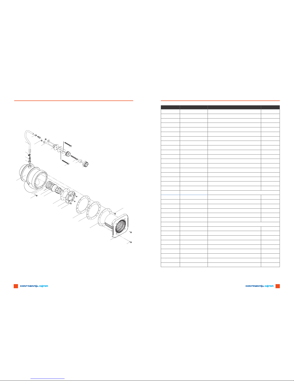
18
15
14
19
19
23
20
15
6
5
7
11/1
11/2
10 4
13
1
2
12
12
3
8
9/1
9/2
9/3
9/4
9/5
25
22
17
16
24
21
Pos Code Description Qty Per Pump
1 PDSSFRGNOZ Face Ring - Nozzle 1
2 PDSSTAP55 Screw - Tapping 5.5 x 19 6
3 PDSSRGCLMP Clamping Ring 1
4 PDSSNO240M Nozzle - Adjustable Flow 1
5 PDSSBUR16 Bushing 1
6 PDCPHCT001 Hose Connector 1/4" 1
7 PDSSHSNG Housing 1
8 PDSSCOVRDW Round Cover (Available in White & Grey) 1
9(1) PDSSBLT625 Bolt - M6 x 25 8
9(2) PDSSBLT620 Bolt - M6 x 20 8
9(3) PDSSBLT625 Bolt - M6 x 25 8
9(4) PDSSBLT640 Bolt - M6 x 40 8
9(5) PDSSBLT645 Bolt - M6 x 45 8
10 PDSSSEANOZ Seat - Nozzle 1
11(1) PDSSSMO62M Spacer Ring -6.2 1
11(2) PDSSSNOZ4M Spacer Ring - 4 2
12 PDSSGKTCLP Gasket - Clamping Ring 2
13 PDSSGASFRG Gasket - Face Ring 1
14-19 PDSSHWHASS Holder with Hose Subassembly
14 PDSSHOSE Hose 8 x 3 1
15 PDSSCHR149 Hose Clamp 14/9 2
16 PDSSHOLREG Holder Air Regulator 1
17 PDSSBLT142 Bolt -1/4-20 x 1-1/2" 2
18 PDSSNUT14 Nut - 1/4-20 2
19 PDSSWASH Washer -1/4" 2
20-25 PDSSREGCOM Subassembly Complete
20 PDSSTPARWH Top Part - Air Regulator 1
21 PDSSBPAREG Bottom Part - Air Regulator 1
22 PDSSPWHREG Bolt - Air Regulator M10 x 80 1
23 PDSSRHAREG Hose Ring - Air Regulator 16 x 30 x 80 1
24 PDSSGASREEG Gasket - Air Control 42 x 11 x 2 1
25 PDSSSCREW Screw - Jet Housing 14 x 1" 2
Not Shown Extension Ring Pre Glued - Available on Request 1
Not Shown Levelling Bar Levelling Bar for Badu Swim Jet Stream II 1
7.0 PARTS LIST FOR BADU®STREAM II

16 17
8.0 FREQUENTLY ASKED QUESTIONS
8.1.1 What size pool do I need?
The BADU®STREAM II can be installed in any size pool. However, we recommend a minimum of
2.1m wide x 4.2m long and 1m deep.
8.1.2 What size plumbing is necessary?
How far away from the BADU®STREAM II can the pump be installed?
For distances up to 6m use 80mm pressure pipe.
For distances 6 to 15m use 100mm pressure pipe or for distances over 15 contact your supplier.
The pump can be placed as close to BADU®STREAM II as local codes will allow.
8.1.3 How many amps does the pump operate at?
The Speck 4hp pumps draw 11.8amps each.
8.1.4 What size breaker do I need?
Please refer to your local wiring code electrician and advise that you require two (2 ) 15amp
circuits for the swimjet pumps.
8.1.5 Does it matter if the housing is installed higher or lower than the manual states?
Yes, the center of the jet must be 250mm BELOW estimated water level for proper performance
of unit.
8.1.6 Can the air regulator be placed elsewhere?
Yes, as long as it is not continuously ooded with water.
8.1.7 Can the pump be placed below water level?
Yes. However, for best performance we recommend ordering pump for ooded suction
(Model 21-80/33G) instead of self-priming (Model 21-80/32 GS). We recommend installing
valves for ease of maintenance.
8.1.8 How far away can the air button function properly? A maximum of 15m Consult factory for
distances over 15m.
8.1.6 Do I need to install a motor starter?
No, the pump is a single phase with internal overload tted.
9.0 WARRANTY
The Australian Competition and Consumer Act (2010) (Cth) (including the Australian Consumer Law)
guarantee certain conditions, warranties and undertakings, and give you other legal rights in relation to the
quality and tness for purpose of consumer goods sold in Australia (Applicable Laws). Our goods come with
guarantees that cannot be excluded under the Australian Consumer Law. You are entitled to a replacement
or refund for a major failure and for compensation for any reasonable foreseeable loss or damage. You are
also entitled to have the goods repaired or replaced if the goods fail to be of acceptable quality and the
failure does not amount to a major failure.
This express warranty provided by Continental Water Systems Pty Ltd (CWS) is in addition to any other
rights and remedies imposed by Applicable Laws that cannot be excluded. Nothing in this warranty is to be
interpreted as excluding, restricting or modifying any Applicable Laws which cannot be excluded, restricted
or modied.
Any express warranty is limited to the length of time specied in the ‘Terms of Express Warranty’ referred
to below, being from the date of purchase and is subject to the conditions set out in the express warranty.
In no event shall CWS be accountable for consequential loss or damage resulting from the breach of any
express warranties.
Under Applicable Laws you may have different or additional legal rights, including longer warranty periods,
which vary from jurisdiction to jurisdiction. Some jurisdictions do not allow certain limitations on how long
an implied warranty lasts, so the limitations in this warranty may not apply to you.
TERMS OF EXPRESS WARRANTY
Your Speck pool pump carries a manufacturer’s warranty of two (2) years on the motor and ve (5) years on
wet end components including casing, diffuser, gland housing, impellor and mechanical seal subject to the
following terms:
• CWS warrants to the original purchaser that all Speck pool pumps manufactured by CWS are free from
defects in workmanship and materials of construction at the time of dispatch from CWS premises.
• The warranty on ancillary components not manufactured by CWS will be limited to the warranty
extended to CWS by the manufacturer of the said ancillary components.
• The replacement of consumable items, including lids and baskets is not covered by this warranty.
EXCLUSIONS
To the maximum extent permitted by Applicable Laws, the warranty will not apply under any of the following
circumstances:
• The Purchaser is in breach of the terms and conditions of sale.
• The product was used for a purpose or under conditions other than what it was intended for.
• The product was repaired, modied or altered by any person other than a CWS Authorised Representatives.
• The product was not installed, maintained and/or operated in complete compliance with the installation
and operating instructions and any instructions provided by CWS.
• The product was operated under adverse conditions including, but not limited to, use with water
18 19
exceeding 35°C, hot operating enclosures with poor ventilation, uctuating power supplies, water
pressure greater than 250kpa, or lack of protection from the weather.
• Normal wear and tear or deterioration associated with the age or use of the product.
• The product was damaged by foreign debris entering via suction pool cleaners, refer to equipment
installation instructions.
• The product was damaged by weather and other environmental conditions including but not limited to
storm, ood, and/or heat wave damage.
• Failure of the mechanical seal due to insufcient water ow caused by any blockage or ingress of foreign
matter of any kind whatsoever.
• Damage to the product caused by the addition of chemicals, salt lter media or any other thing through
the skimmer box.
• Failures or any defects in component, part or operating function of the product, which is in the opinion
of CWS the result from misuse, negligence, rebuilds or modication, incorrect installation by persons
that are not CWS Authorised Representatives.
LIMITATIONS
Except to the extent permitted by Applicable Laws, breach of a condition or warranty, shall be limited to
replacing or acquiring the same equipment (or any part thereof) or the services supplied.
The maximum liability incurred by CWS shall not exceed in any case the contract price for the equipment
or the product parts claimed to be defective. Further, CWS shall not be liable for any loss, damage or delay
directly or indirectly caused by any malfunction of or defect of or failure of the equipment other than as
expressly stated in this warranty.
Subject to Applicable Laws, the repair or replacement of the product or part of the product is the absolute
limit of CWS liability under this express warranty.
WARRANTY CLAIMS
If you consider that the product which you have purchased is not of acceptable quality, has a latent defect
or is otherwise not compliant with the warranties, conditions, undertakings and legal rights you have under
Applicable Laws you can make a claim under this warranty by contacting:
Continental Water Systems Pty Ltd
5 Anvil Road, SEVEN HILLS NSW 2147
Email: sales@continentalwater.com.au
All onsite service work is subject to a service call charge which will be quoted and which must be accepted
by the customer before any or all work will be carried out.
Any equipment requiring warranty repair (alleged) must be returned to the place of purchase and or nearest
CWS approved stockist (prepaid), as soon as the purchaser becomes aware of any fault. Neither CWS
nor the approved CWS stockist shall be responsible for any goods damaged in transit. If the equipment is
found to be defective after examination it will be repaired or replaced free of charge and returned freight
collect. If the equipment is not defective and outside of warranty all repair or replacement costs will be
charged to the purchaser or their representative and returned freight collect.
All Warranty claims must be accompanied by the proof of purchase, alleged defect and any appropriate
documentation (Historical and maintenance records).
8.2 CUSTOMER WARRANTY INFORMATION
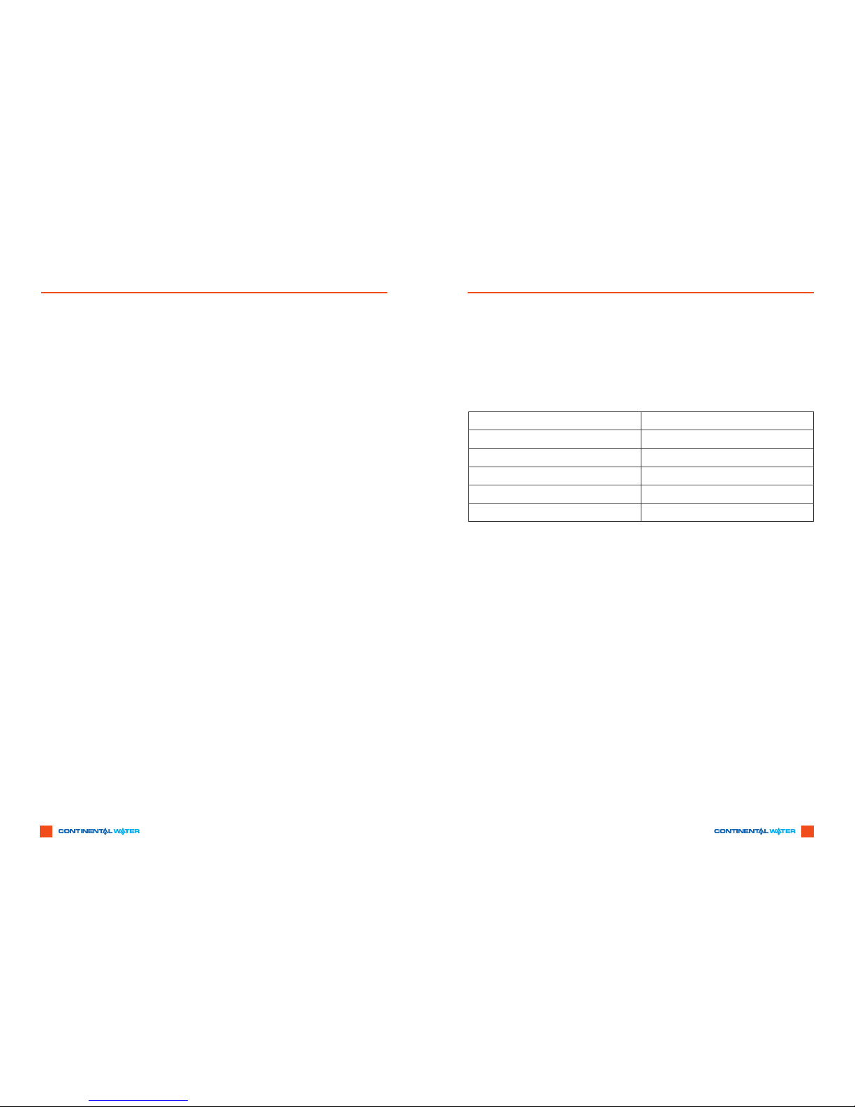
8.2.1 Please complete the information below at time of installation and retain in the event you need to
le a warranty claim
8.2.1 Please complete the information below at time of installation and retain in the event you need to
le a warranty claim
Model Number
Pump Serial Number
Purchase Date
Purchased From
Installation Date
Installer

20
1300 166 253 for Sales and Service
esales@continentalwater.com.au / accounts@continentalwater.com.au ABN: 71 050 287 735
New South Wales Ofce Victorian Ofce Queensland Ofce New Zealand Ofce
t(02) 8814 2800 t(03) 8794 3800 t(07) 3434 1100 t 0011 64 9570 9570
f (02) 9838 7030 f(03) 9702 3941 f(07) 3219 2266 f 0015 64 9527 7641
Other manuals for Badu Stream II
1
Table of contents
Popular Plumbing Product manuals by other brands

clage
clage MBX 3 Lumino Operating and installation instructions

RAVAK
RAVAK R-box Multi RB 071.50 Mounting instruction

Kohler
Kohler K-11340X Installation and care guide

Graff
Graff ADLEY E-3852-C2 Instructions for assembly and use

Kraus
Kraus Urbix FF-101 installation guide

Allen + Roth
Allen + Roth 3074-02618-ARCH manual

Franke
Franke MIRANIT F5ST2024 Installation and operating instructions

SANYone
SANYone SARAH 39001 installation guide

Grohe
Grohe 41721XX0 Specification sheet

American Standard
American Standard Tropic 911903-0070A parts list

Steinberg
Steinberg iFlow 390 4110 installation instructions

Jacuzzi
Jacuzzi SANCTUARY 1 owner's manual


