Speco HT-7248FFI User manual

HT7248FFi
540 Line Color Dome Camera
Intensifier Series, Focus Free
Wall & Ceiling Mountable
Please read this manual thoroughly before operation and keep
it handy for further reference.

WARNING & CAUTION
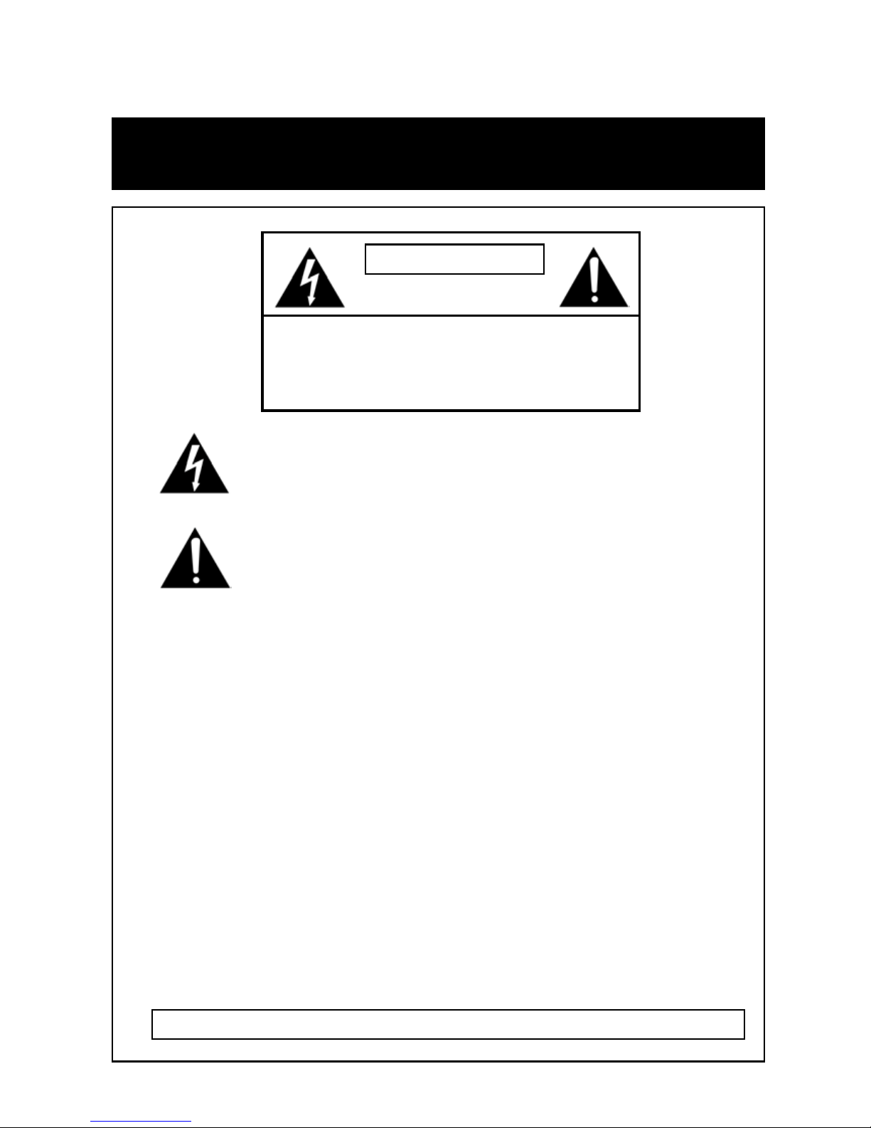
The lighting flash with an arrowhead symbol, within an equilateral triangle is
Intended to alert the user to the presence of un-insulated “dangerous voltage”
within the product’s enclosure that may be of sufficient magnitude to constitute
a risk of electric shock to persons____________________________________
The exclamation point within an equilateral triangle is intended to alert the user
to the presence of important operating and maintenance (serving) instructions
in the literature accompanying the appliance__________________
INFORMATION -This equipment has been tested and found to company with
limits for a class a digital device Pursuant to part 15 of the FCC rules.
These limits are designed to provide reasonable protection against harmful
Interference When the equipments operated in a commercial environment.
This equipment generates, uses, and Can Radiate radio frequency energy and
if not installed and used in accordance with the instruction manual, may Cause
Harmful interference to radio communications. Operation of this equipment in a
residential area is likely to cause harmful interference in which
Case the user will be required to correct the interference at his own expense.
WARNING – Change or modification not expressly approved by the manufacturer could void
the user’s authority to operate the equipment__________________________________
CAUTION : To prevent electric shock and risk of fire hazards.
DO NOT use power sources other than that specified.______
DO NOT expose this appliance to rain or moisture.000
This installation should be made by a qualified service person and should conform to all local codes.
RISK OF ELECTRIC SHOCK
DO NOT OPEN
CAUTION : TO REDUCE THE RISK OF ELECTRIC SHOCK
DO NOT REMOVE COVER (OR BACK).
NO USER SERVICEABLE PARTS INSIDE
REFER SERVICINGTO QUALIFIED
SERVICE PERSONNEL._______________
CAUTION

Contents
3
Package Contents
4
Precautions
5~8
Camera Installation
9~10
Features
11~16
OSD Setting
17~18
Troubleshooting
19
Specification
20
Dimensions
21
Warranty
2

PACKAGE CONTENTS
•Please make sure that the following items are included
in the package:
1 HT7248FFi Camera
2 Mounting Screws
1 Chameleon Dome Cover
1 Video Test Cable
Please leave this manual with the end-user for future
reference.
3

PRECAUTIONS
•THIS DOME CAMERA SHOULD BE ONLY INSTALLED BY
QUALIFIED PERSONNEL
•TO PREVENT A FIRE OR ELECTRICAL HAZARD PLEASE USE
PROPER POWER CABLE. THE DOME COVER SHOULD BE
TREATED WITH CARE
•DO NOT CELAN THE COVER WITH AN ABRAISIVE CLEANING
MATERIAL - PLEASE USE A SOFT CLOTH OR TISSUE TO
CLEAN THE DOME COVER
•THERE ARE NO USER-SERVICEABLE PARTS INSIDE.
PLEASE DO NOT DISASSEMBLE THIS CAMERA OTHER THAN
TO MAKE INITIAL ADJUSTMENTS
•PLEASE USE A UL APPROVED REGULATED 24 VOLT AC OR
12 VOLT DC POWER SUPPLY
•PLEASE USE APPROPRIATE LOW VOLTAGE POWER CABLE
TO PREVENT FIRE OR ELECTRICAL SHOCK
•PLEASE INSURE THAT YOUR INSTALLATION AREA CAN
SUPPORT THE WEIGHT OF THE CAMERA
•PLEASE HANDLE THIS CAMERA CAREFULLY:
-DON
’T USE A STRONG OR ABRASIVE DETERGENT WHEN
CLEANING THE CAMERA.
-DON
’T EXPOSE THE CAMERA TO DIRECT SUN
4

CAMERA INSTALLATION
1. CONNECT POWER CABLE
1) WHEN USING 12 VOLTS DC (constant voltage 600 mA)
-CONNECT ACCESSORY CABLE TO THE CABLE LEAD
OF THE CAMERA AND CONNECT 12V DC POWER SUPPLY.
2) WHEN USING 24 VOLTS AC (40 Volt Amps)
3) CONNECT VIDEO CABLE
-CONNECT BNC CABLE TO THE BNC JACK.
4) CONNECT RS-485 CABLE
-CONNECT 2WIRE CABLE TO THE 485PORT AS BELOW.
YELLOW:VIDEO OUT
POWER SUPPLY
CONNECT
POWER INPUT:RED
CENTER:(+)
CONNECT
BLACK:(-)
CAMERA RED(+)
POWER SUPPLY
AC 24V
5

CAMERA INSTALLATION
2. CHAMELEON COVER INSTALLATION
1) If you wish to change the color of the HT-7248FFi,
place the Chameleon Dome over the camera
* Spray the color of your choice onto the Chameleon cover
* If necessary, apply a second coat
* Painting method for the Chameleon Dome
Place the Chameleon Dome over the HT-7248FFi and push until
it snaps into position.
●Notes : Optional painting before installation
6

CAMERA INSTALLATION
3. CONTROL BOARD
1) Video Test Terminal
For second video output
2) OSD (On Screen Display) Joy stick
Press the Joy stick for one second until the OSD menu tree
appears on the screen. Move the Joy Stick up, down, left &
right to control the OSD functions.
3) DIP Switch setting for RS485
Please see the next page for controlling this switch.
4) Lens adjustment (for Zoom) Joy stick
Adjust the Joy stick left or right to control between TELE &
WIDE, Focus is automatically matched without any adjustment.
1 2 3 4
7

CAMERA INSTALLATION
4. DIP Switch Setting for RS-485 (Pelco-D)
2) Baud rate Setting
to set Baud rate, please refer the chart below.
1 2 3 4 5 6
1) Address Setting
to set Camera Address, place switches based on below chart.
8

Features
SLC
When the image is in front of strong background lighting,
your camera allows you to get a clear image.
INTENSIFIER
1/3 inch density CCD and digital processor permit high quality
pictures to be captured in very low light condition.
High Resolution
Horizontal resolution of 540 TV lines is achieved by using a
SONY Double Speed CCD with 410,000 pixels, yielding pictures
with a high S/N ratio..
Motion Detection
Built in motion detector with adjustable areas of coverage will
flash a warning on the screen when motion is detected.
9

OSD
All camera functions are menu driven for easy use.
Dynamic Noise Reduction
The Intensifier camera has a DSP chip that can remove image
noise efficiently showing clean images in low light conditions.
ELECTRONIC DAY/NIGHT
The Intensifier camera can show color pictures in all lighting
conditions, or you can have it automatically switch to a B/W
picture in low light conditions
MANUAL / AUTO IRIS LENS
The Intensifier camera will work with auto iris, manual iris and
fixed iris lenses.
10

Operating your camera
OSD Function
SETUP MENU LENS TYPE
●DC IRIS
SHUTTER TYFE
●ELC ●FIXED ●MANUAL
WHITE BALANCE
●ATE ●AWC ●MANUAL
SLC
●HIGH ●MIDDLE ●LOW ●OFF
AUTO GAIN
●HIGH ●MIDDEL ●LOW ●OFF
REDUCE NOISE
●HIGH ●MIDDLE ●LOW ●OFF
INTENSI FIER
●AUTO ●OFF
NEXT PAGE
●CAMERA TITLE ●DAY/NIGHT ●SYNC
●MOTION ●PRIVACY ●REVERSE
●DETAIL ●DEFAULT ●PAGE1
EXIT
11

SETUP Menu Functions
1. LENS (DC) – Lens is static with DC auto iris lens only
2. SHUTTER (Option : OFF / FLK / MANUAL/ ESC)
Flickerless mode (FLK) reduces on-screen flickering.
Electronic Shutter Control (ESC) adjusts brightness level
on screen.
Manual mode allows you to adjust the shutter speed from
1/60~1/120,000 of a second (NTSC).
3. WHITE BAL. (Option : ATW / MANUAL / AWC)
Select Auto Tracking White Balance (ATW) when the color
temp. is 2400°K~12000°K.
Manual mode allows you to increase or decrease the red
or blue factor on screen.
Auto White Balance Control (AWC) automatically adjusts
the white balance to your specific environment.
4. SLC (Speco Light Compensation) - BACKLIGHT
It provides intelligent light level control to overcome severe
Backlight conditions by Low, Middle & High level control.
12

5. Auto Gain ( Low / Middle / High)
Increase the GAIN level to brighten the picture.
(noise / distortion may develop)
6. REDUCE NOISE (Low / Middle / High)
Reduces noise/distortion on the screen, Increasing the
REDUCE NOISE level reduces noise but may introduce video
Artifacts, it is deactivated if AGC is turned off.
7. INTENSIFIER
Automatically provides a clear image under low-light
conditions. You can control the maximum low-light
magnification from 2x to 128x, It is deactivated when
SHUTTER is set to FLK mode.
8. NEXT PAGE
Takes you to the special functions.
9. EXIT
Exits the SETUP menu and returns to video monitoring.
13

NEXT PAGE Menu Functions
1. CAMERA ID
UP, DOWN, LEFT, RIGHT menu control = Select a
character, then press (SETUP)MENU to accept it.
The character is saved and the title cursor at the bottom of the
screen moves to the next position.
←→= Go back or forward in the title name to make changes.
CLR = Delete the entire name and start again.
POS = Position the camera title on the screen.
Press (SETUP)MENU to confirm the position.
END = Accept the new name.
2. COLOR (Auto / On)
Sets the camera to either automatic color/black and white or
full-time color mode.
* Auto : The camera will switch into B/W mode under low light
conditions.
* Color : Always display a color picture.
OSD Key may not work for 3 seconds when COLOR/ BW
mode is changed
14

3. SYNC (INT / Line Lock)
INT : When line lock is not required.
It synchronize the vertical interval sync pulse of your
camera with other equipment to reduce the effect of
picture roll on the monitor.
L/L : Adjust the vertical phase (VPH) from 000 ~ 359
Line Lock is only available with 24VAC power.
4. MOTION
Detects moving objects on screen and displays MOTION
DETECTED along with the number of movements counted.
Allows you to select the area on screen you want to observe.
AREA SEL = Select a motion detection grid (top left, top
right, bottom left, bottom right) to modify.
AREA STATE = Activate or deactivate the selected grid.
TOP/DOWN/ = Press LEFT or RIGHT menu control left or
LEFT/RIGHT right to alter the dimensions of the selected
grid.
15

5. PRIVACY
Allows you to mask certain areas of the screen from
observation
AREA SEL = Select a motion detection grid (top left, top
right, bottom left, bottom right) to modify.
AREA STATE = Activate or deactivate the selected grid.
TOP/DOWN/ = Press LEFT or RIGHT menu control left or
LEFT/RIGHT right to alter the dimensions of the selected
grid.
6. MIRROR
Produces a horizontal mirror image on screen.
7. SHARPNESS
Sharpens the image on screen. You can adjust the sharpness
Level from 0~31 (excessive sharpening may cause picture
noise to develop).
8. RESET
Restores all factory default settings.
9. RETURN
Returns to the main SETUP menu.
16

Troubleshooting
If you have trouble operating your camera, refer to the following
●Have you set ‘MOTION DET.’menu to off?
●Have you set ‘MD LEVEL’to too how?
●Have you set ‘MD ARAEA’properly
MOTION
DETECTION
function is not active.
● Check that you have properly connected
the camera to an appropriate power source.
The camera is not
working properly, and
the surface of the
camera is not.
● Adjust the contrast feature of the monitor.
●If you have an intermediate device, set the
75Ω/Hi-z properly.
The image on the
screen is dark.
● Is lens stained with dirt? Clean your lens with
soft,
clean cloth.
● Set the monitor to proper condition.
● If the camera is exposed to too strong light
change the camera position.
● Adjust the lens’focus properly.
The image on the
screen is dim.
● Check that the power cord and line connection
between the camera and monitor are proper
● Check that you have properly connected VIDEO
cable the camera VIDEO output jack.
Nothing appears on
the screen.
Solution
Problem
17

● Have you connected your camera to DC power
source? Connect it to AC power source.
L/L mode isn’t able
to be selected.
● Is the camera facing to direct sunlight or
fluorescent
lighting? Change the camera position.
The image on the
screen flickers.
● Check that you have properly set the
‘WHITE BALANCE ’menu
The color of the
picture is not
matched.
Solution
Problem
18

SPECIFICATIONS
Internal / Line Lock selectableSynchronization
Focus Free Lens 3.5~10mmLENS TYPE
500mA (DC) / 6.6W (AC)Power Consumption
-29℃~ +50℃( - 20℉~122℉)Operational Temperature
ON / OFF (4 Programmable Zone)PRIVACY Function
Built –inOn Screen Display ( O.S.D )
MD1 / MD2 / OFFMotion Detection
50dB (Weight On)S/N ( Y signal)
OFF / LOW / MIDDLE / HIGHReduction Noise
W-ATW / S-ATW / AWC /MANUALWHITE BALANCE
0.002Lux (intensifier) 0.3Lux (shutter)Min. Illumination
30% ~90% RHOperational Humidity
Built-in ( selectable limit ~ X128)INTENSIFIER
1/60 ~ 1/200,000 secElectric Shutter Speed
AGC-L, AGC-M, AGC-H, OFF selectableGain Control
540 TV LineResolution
1.0V [p-p] Composite, 75ΩVideo Output
2 : 1 Interlaced 525 Lines / 60 Fields / 30
Frames
Scanning System
1 : 1.3 ~2.0Maximum Aperture Ratio
768(H) x 494(V) , 1/3”CCDEffective Pixels
811(H) x 508(V) , 1/3”CCDTotal Pixels
1/3”, SONY SUPER HAD CCD, 410,000 pixelsImage Sensor
12VDC & 24VAC ( Dual Voltage )Power Source
HT – 7248FFiITEM
19
Other manuals for HT-7248FFI
1
Table of contents
Other Speco Security Camera manuals

Speco
Speco O8VB1 User manual

Speco
Speco VL-650 Series User manual

Speco
Speco O4VB2G User manual

Speco
Speco VL-12 Series User manual

Speco
Speco CVC-644DC User manual

Speco
Speco O4FT2W User manual

Speco
Speco CVC6146SCFF User manual

Speco
Speco INTENSIFIER3 HT647HRTP User manual

Speco
Speco O2T7 User manual

Speco
Speco LEDomeW Dome Camera User manual
Popular Security Camera manuals by other brands

Bosch
Bosch AUTODOME IP starlight 5000i NDP?5512?Z30C installation manual

Smartec
Smartec STC- 3080 ULTIMATE user manual

Sanyo
Sanyo VCC-HD5600 - Full HD 1080p Day/Night Pan-Tilt-Zoom... Product guide specification

D-Link
D-Link DCS-2210 Quick installation guide

Ebode
Ebode IPV58P2P quick start guide

JVC
JVC TK-C205VP instructions