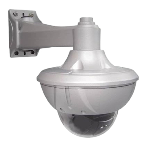
Speco ONSIP OPTZ36XO User manual

O
ON
NS
SI
IP
P
O
OP
PT
TZ
Z
O
O/
/I
I
U
Us
se
er
rs
s’
’
G
Gu
ui
id
de
e
Rev.1.0 (Nov., 2011)
1
ONSIP OPTZ36XO
ONSIP OPTZ36XI

O
ON
NS
SI
IP
P
O
OP
PT
TZ
Z
O
O/
/I
I
U
Us
se
er
rs
s’
’
G
Gu
ui
id
de
e
Rev.1.0 (Nov., 2011)
2
Revision History
Date
Rev No.
Description
2011-11-01
1.0
First manual revision creation.

O
ON
NS
SI
IP
P
O
OP
PT
TZ
Z
O
O/
/I
I
U
Us
se
er
rs
s’
’
G
Gu
ui
id
de
e
Rev.1.0 (Nov., 2011)
3
Warning & Cautions
If you fail to read this information and handle the product incorrectly, faulty or malfunction as well as
death or serious injury may occur.
This Unit should be installed by train
ed personnel.
Immediately stop using when the product
emits smoke or abnormal heat.
Never install the product in area exposed to
oil or gas.
Never install the product on a ceiling
that cannot hold its weight.
Never touch the power cord with wet hands.
Clean only with dry cloth.
Never use the product in extremely high or
low temperature condition.
Never drop, hit, strongly nor vibrate the
product.
Never expose the product to direct sunlight
or severe ray.
Never touch the front glass of the product.

O
ON
NS
SI
IP
P
O
OP
PT
TZ
Z
O
O/
/I
I
U
Us
se
er
rs
s’
’
G
Gu
ui
id
de
e
Rev.1.0 (Nov., 2011)
4
Indications:
Warning: Death or Serious Injury will occur without following Warning.
Caution : Operational Problem(Faulty & Malfunction) will occur without complying with Caution
Reference : Technical Information for Users

O
ON
NS
SI
IP
P
O
OP
PT
TZ
Z
O
O/
/I
I
U
Us
se
er
rs
s’
’
G
Gu
ui
id
de
e
Rev.1.0 (Nov., 2011)
5
Table of Contents
Table of Contents................................................................................ 5
1. Introduction................................................................................... 7
1.1. Overview of ONSIP OPTZ36XO/I................................................................... 7
1.2. Specification........................................................................................... 8
1.2.1. Basic Specification
1.2.2. Detailed Specification of Camera Module & PTZ오류! 책갈피가 정의되어 있지 않습니다.
1.2.3. Basic Specification오류! 책갈피가 정의되어 있지 않습니다.
1.2.4. Detailed Specification of Camera Module오류! 책갈피가 정의되어 있지 않습니다.
1.3. Application of ONSIP OPTZ36XO/I................................................................. 9
2. Production Description................................................................... 10
2.1. Package Contents .................................................................................... 10
2.1.1. ONSIP OPTZ36XO.......................................................................................................................10
2.1.2. ONSIP OPTZ36XI ........................................................................................................................10
2.2. Preview .................................................................................................. 11
2.3. Physical Description.................................................................................. 12
2.3.1. External View................................................................................................................................12
2.3.2. Bottom View & Connection Diagram............................................................................................12
2.3.3. External & Internal View...............................................................................................................14
2.4. Functional Description ............................................................................... 16
3. Bracket Installation ...................................................................... 19
3.1. ONSIP OPTZ36XO ................................................................................... 19
3.1.1. Basic Components & Mounting Accessories................................................................................19
3.1.2. Preparation...................................................................................................................................19
3.1.3. Installation using Walling Mount Type..........................................................................................21
3.2 ONSIP OPTZ36XI...................................................................................... 23
3.2.1. Preparation...................................................................................................................................23
3.2.2. Installation using Ceiling Mount Type...........................................................................................24
3.2.3. Installation using Embedded Mount Type ....................................................................................25


O
ON
NS
SI
IP
P
O
OP
PT
TZ
Z
O
O/
/I
I
U
Us
se
er
rs
s’
’
G
Gu
ui
id
de
e
Rev.1.0 (Nov., 2011)
6
4. Installation .................................................................................. 28
4.1. Required System Specification.................................................................... 28
4.2. Quick Installation Guide ............................................................................. 29
5. Trouble Shooting.......................................................................... 35
5.1. No Video on Viewer................................................................................... 35
5.2. Windows vista and Windows 7 User for Record & Capture Problem ................... 36
5.3 Technical Inquiry........................................................................................ 39
6. Appendix.................................................................................... 40
6.1. FAN & Heater .......................................................................................... 40
6.2. DIP Switch Setting.................................................................................... 42

O
ON
NS
SI
IP
P
O
OP
PT
TZ
Z
O
O/
/I
I
U
Us
se
er
rs
s’
’
G
Gu
ui
id
de
e
Rev.1.0 (Nov., 2011)
7
1. Introduction
1
1.
.1
1.
.
O
Ov
ve
er
rv
vi
ie
ew
w
o
of
f
O
ON
NS
SI
IP
P
O
OP
PT
TZ
Z3
36
6X
XO
O/
/I
I
ONSIP OPTZ36XO/I, as a state-of-the-art 1Channel Speed Dome Network Camera based on integrated
Embedded Software technologies such as H.264 & MJPEG, G.726 & PCM Video & Audio Compression,
Embedded Web Server, Embedded Streaming Server, various Network Protocols, transmits synchronized video
and audio data in real time through IP Network as well as supports bi-directional audio communication by
allowing transmission of audio from Client PC to ONSIP OPTZ36XO/I.
ONSIP OPTZ36XO/I, with completed Integration with analog CCTV camera, Digital and network technology, is
applicable for various sectors such as Security, Remote Monitoring, Remote Education, Simple Video
Conference as well as Internet Broadcasting System etc.

O
ON
NS
SI
IP
P
O
OP
PT
TZ
Z
O
O/
/I
I
U
Us
se
er
rs
s’
’
G
Gu
ui
id
de
e
Rev.1.0 (Nov., 2011)
8
1
1.
.2
2.
.
S
Sp
pe
ec
ci
if
fi
ic
ca
at
ti
io
on
n
1
1.
.2
2.
.1
1.
.
B
Ba
as
si
ic
c
S
Sp
pe
ec
ci
if
fi
ic
ca
at
ti
io
on
n
Class
Description
Video
Compression
H.264 / MJPEG
Resolution
**Refer to the datasheet
Audio
(Bi-directional)
Up Stream
32 Kbps G.726
Down Stream
64 Kbps PCM
Network
Interface
RJ-45, 10/100 Mbps
Access Network
Static, DHCP, PPP/PPPoE
Protocol
IPv4/6, TCP, UDP, IGMP, ICMP, ICMPv6 etc.
I/O
Sensor
4
NC, NO Selectable
Relay Output
2
Alarm or Remote ON/OFF Control (30V, 1A)
RS-232C
Factory Default
Mic/Line In
Selectable on Admin Page
Line Out
1 V p-p Audio Output for Amp embedded Speaker
CVBS Output
Supported
Power
PoE
Supported
AC In
12VDC Adaptor (higher than 2 Amp)
Housing
Water-Proof
IP66
Heater
Refer to Installation Configuration
Installation Type
Bracket
Wall, Ceiling, Ceiling Embedded Type
Motion Detection
3 Regions
Optional Shape & Sensitivity for 3 Regions
Upgrade
Remote F/W Upgrade via IP Network
Management & Configuration
Remote Management & Configuration using IP Network and
Admin Tool Page
Client/Viewer
Web Viewer
Simple Access via Internet explorer
Speco-NVR
CMS Software
Dynamic IP
DDNS support
Supported by Speco Technology’s Management Server
Security Management
802.1x authentication, User ID & Password Protection, IP
Filtering, Audio per user and Bi-directional audio
communication configuration control
Time
Configuration
Management
Sync to PC
Sync to PC Time
Manual
Manual Configuration
Internet Time Server
Sync to Time Server
DLS
Summer Time Configuration

O
ON
NS
SI
IP
P
O
OP
PT
TZ
Z
O
O/
/I
I
U
Us
se
er
rs
s’
’
G
Gu
ui
id
de
e
Rev.1.0 (Nov., 2011)
9
1
1.
.3
3.
.
A
Ap
pp
pl
li
ic
ca
at
ti
io
on
n
o
of
f
O
ON
NS
SI
IP
P
O
OP
PT
TZ
Z3
36
6X
XO
O/
/I
I
- Security Surveillance (Building, Stores, Manufacturing Device, Parking Lot, Bank, Public Office &
Military etc)
- Remote Monitoring (Hospital, Kindergarten, Traffic Status, Public Area)
- Video Conference, Remote Lecture, Internet Broadcasting
- Climate & Environment Surveillance

O
ON
NS
SI
IP
P
O
OP
PT
TZ
Z
O
O/
/I
I
U
Us
se
er
rs
s’
’
G
Gu
ui
id
de
e
Rev.1.0 (Nov., 2011)
10
2. Production Description
2
2.
.1
1.
.
P
Pa
ac
ck
ka
ag
ge
e
C
Co
on
nt
te
en
nt
ts
s
Open the package and check if the followings are included;
2
2.
.1
1.
.1
1.
.
O
ON
NS
SI
IP
P
O
OP
PT
TZ
Z3
36
6X
XO
O
Contents
Description
Remark
Bracket & Housing
Outdoor Housing, Wall Mount Bracket
Accessories
Screw (M4x15 4EA), Safety Cable
Manual
Housing Installation Manual
IP Camera
Camera body
Tools & Accessories
Wrench, Safety Cable, Cable Tie, Terminal Block
(2Pin, 3Pin , 5Pin ,6Pin : 1EA), Screw(Ø 3x6 2EA,
Ø 4x16 5EA)
CD
Software & Product User Manual
Quick Reference
Quick Installation Guide
2
2.
.1
1.
.2
2.
.
O
ON
NS
SI
IP
P
O
OP
PT
TZ
Z3
36
6X
XI
I
Content
Description
Remark
IP Camera
Camera body
Tools & Accessories
Wrench, Safety Cable, Cable Tie, Terminal Block
(2Pin, 3Pin , 5Pin ,6Pin : 1EA), Screw(Ø 3x6 2EA,
Ø 4x16 5EA)
CD
Software & Product User Manual
Quick Reference
Quick Installation Guide

O
ON
NS
SI
IP
P
O
OP
PT
TZ
Z
O
O/
/I
I
U
Us
se
er
rs
s’
’
G
Gu
ui
id
de
e
Rev.1.0 (Nov., 2011)
11
2
2.
.2
2.
.
P
Pr
re
ev
vi
ie
ew
w
ONSIP OPTZ36XO/I
IP-Installer
CMS Software
(Speco-NVR)
Speed Dome Network Camera
IPAssignment Program
PC based Client for
monitoring/storing Video/Audio
transmitted form Product
(Max. 64CH supported)

O
ON
NS
SI
IP
P
O
OP
PT
TZ
Z
O
O/
/I
I
U
Us
se
er
rs
s’
’
G
Gu
ui
id
de
e
Rev.1.0 (Nov., 2011)
12
2
2.
.3
3.
.
P
Ph
hy
ys
si
ic
ca
al
l
D
De
es
sc
cr
ri
ip
pt
ti
io
on
n
2
2.
.3
3.
.1
1.
.
E
Ex
xt
te
er
rn
na
al
l
V
Vi
ie
ew
w
Fig 2-1. External View of ONSIP OPTZ36XO/I
2
2.
.3
3.
.2
2.
.
B
Bo
ot
tt
to
om
m
V
Vi
ie
ew
w
&
&
C
Co
on
nn
ne
ec
ct
ti
io
on
n
D
Di
ia
ag
gr
ra
am
m
Fig 2-2-1. Terminal Block, LAN & Power Connector
12VDC

O
ON
NS
SI
IP
P
O
OP
PT
TZ
Z
O
O/
/I
I
U
Us
se
er
rs
s’
’
G
Gu
ui
id
de
e
Rev.1.0 (Nov., 2011)
13
Fig 2-2-2. Terminal Block, LAN & Power Connector

O
ON
NS
SI
IP
P
O
OP
PT
TZ
Z
O
O/
/I
I
U
Us
se
er
rs
s’
’
G
Gu
ui
id
de
e
Rev.1.0 (Nov., 2011)
14
2
2.
.3
3.
.3
3.
.
E
Ex
xt
te
er
rn
na
al
l
&
&
I
In
nt
te
er
rn
na
al
l
V
Vi
ie
ew
w
Fig 2-3-1. Connector Part

O
ON
NS
SI
IP
P
O
OP
PT
TZ
Z
O
O/
/I
I
U
Us
se
er
rs
s’
’
G
Gu
ui
id
de
e
Rev.1.0 (Nov., 2011)
15
Fig 2-3-2. Connector Part
1. Bubble
2. Lock Screw
3. Camera
4. Dip Switch1
5. Dip Switch2
6. Lock Holder
7. Alarm
8. Line Out
9. LAN (100 Base-T)
10. RS-485 (D+, D-)
11. Power Input (DC12V)
12. Aux
13. Video out (Analog CVBS)
14. Power LED
15. Mic / Line In
16. Fan / Heater

O
ON
NS
SI
IP
P
O
OP
PT
TZ
Z
O
O/
/I
I
U
Us
se
er
rs
s’
’
G
Gu
ui
id
de
e
Rev.1.0 (Nov., 2011)
16
Fig 2-4. Outdoor Housing
2
2.
.4
4.
.
F
Fu
un
nc
ct
ti
io
on
na
al
l
D
De
es
sc
cr
ri
ip
pt
ti
io
on
n
AC Power
Connect 24 Volt AC adaptor to this terminal for supplying power to the network camera.
DC Power
Connect 12 Volt DC adaptor to this terminal for supplying power to the network camera.
AC adapter which is compliant to the specification for ONSIP OPTZ36XO/I should be used.
Misuse of power supply can cause damage to ONSIP OPTZ36XO/I. Speco assumes no
responsibility for misuse of the power supply.
MIC/LINE IN
Connect external audio source or microphone.
Line Out
Connect speakers with built in amplifier. Audio from remote site is output through Line out in bi-directional
audio mode.
100Base-T
100Mbps Ethernet connector (RJ-45). 2 LEDs on the Ethernet connector shows the status of ONSIP
OPTZ36XO/I as the followings:

O
ON
NS
SI
IP
P
O
OP
PT
TZ
Z
O
O/
/I
I
U
Us
se
er
rs
s’
’
G
Gu
ui
id
de
e
Rev.1.0 (Nov., 2011)
17
-Status LED (Dual Color - Red/Green): It will be lit in green or red depending on the status.
Green: Green color indicates that the camera is in normal operation mode. Continuous green
indicates that data transmission is possible. Blinking green means that someone is
connected to ONSIP OPTZ36XO/I.
Red: Continuous or blinking red indicates that hardware is in abnormal condition.
Red/Green LED will be lit with red momentarily and it will be lit with green after a while when
power is applied into ONSIP OPTZ36XO/I.
LINK/LAN LED (Orange): It will be lit with orange color when network cabling is all right. Blinking
orange color indicates that normal data transmission is under way. Off state indicates that there is
trouble in network connection.
HEATER/FAN
Used for connecting power cable of heater and fan. Power cable of heater and fan is in the bracket.
Alarm In/Out (ALARM/AUX)
Used for connecting alarm sensor, alarm annunciation device to ONSIP OPTZ36XO/I.
Class
Description
Alarm IN
Sensor In (+). NC/NO Selectable in Admin Mode
Alarm IN GND
Ground for Sensor In
Aux OUT
Alarm Output Terminal
Aux OUT(GND)
Ground for Sensor Output
Aux
Relay output is provided for connecting alarm devices or for remote on/off control of devices such as light.
Relay is normal open and it will be closed upon alarm annunciation or remote on. The relay is capable
of switching 30V AC/DC, 2A. For the application which needs power switching beyond this limit, use
additional relay switch as shown as below figure.

O
ON
NS
SI
IP
P
O
OP
PT
TZ
Z
O
O/
/I
I
U
Us
se
er
rs
s’
’
G
Gu
ui
id
de
e
Rev.1.0 (Nov., 2011)
18
Fig 2-5. Relay Connection Diagram (Left: lower than 30V, 2A, Right: Higher than 30V 2A)
Alarm
Connect external alarm sensor. Examples of sensing devices are infrared sensor, motion sensor,
heat/smoke sensor, magnetic sensor, etc. Connect the two wires of the sensors to “SNS In”. The sensor
type (NC/NO) can be set in admin page. 10mA can be flown into sensor device. Multiple sensor devices
can be connected in parallel.
Sensor
Device
Sensor
Power
Supply
NO/NCType
Sensor1-
Sensor1+
+12V GND
Sensor
Device
Sensor
Power
Supply
Open CollectorType
Photo Coupler
Fig 2-6. Sensor Input Connection Diagram

O
ON
NS
SI
IP
P
O
OP
PT
TZ
Z
O
O/
/I
I
U
Us
se
er
rs
s’
’
G
Gu
ui
id
de
e
Rev.1.0 (Nov., 2011)
19
3. Bracket Installation
3.1. ONSIP OPTZ36XO
3
3.
.1
1.
.1
1.
.
B
Ba
as
si
ic
c
C
Co
om
mp
po
on
ne
en
nt
ts
s
&
&
M
Mo
ou
un
nt
ti
in
ng
g
A
Ac
cc
ce
es
ss
so
or
ri
ie
es
s
3
3.
.1
1.
.2
2.
.
P
Pr
re
ep
pa
ar
ra
at
ti
io
on
n
1. Open the Dome Cover by unscrewing with wrench.

O
ON
NS
SI
IP
P
O
OP
PT
TZ
Z
O
O/
/I
I
U
Us
se
er
rs
s’
’
G
Gu
ui
id
de
e
Rev.1.0 (Nov., 2011)
20
2. Configure the DIP Switch by referring Appendix.
3. Place the Dome Cover and screw.
-When using system controller for the control of the dome, always set the RS-485
communication channel to be: 2400 bps, 8 bit, 1 stop bit, no parity.
This manual suits for next models
1
Table of contents
Other Speco Security Camera manuals

Speco
Speco CVC-628M User manual

Speco
Speco WDR-R3 User manual

Speco
Speco VLB11SCSFF User manual

Speco
Speco O5LT1 User manual

Speco
Speco VLT4DG User manual

Speco
Speco CVC-5715DNV User manual

Speco
Speco HTINT58K User manual

Speco
Speco PVS-CAMC User manual

Speco
Speco O4FT2W User manual

Speco
Speco LEDome User manual

Speco
Speco O4VT1NG User manual

Speco
Speco Flexible Intensifier O8FD4M User manual

Speco
Speco O5D4M User manual

Speco
Speco VLEDT1HG/W Series User manual

Speco
Speco 700Line IntensifierH CVC6246H User manual

Speco
Speco CVC-1705 User manual

Speco
Speco CVC-190 User manual

Speco
Speco O2D60M User manual

Speco
Speco O4VD2 User manual

Speco
Speco CVC-607EXCM25 User manual