SPECS XR 50 User manual
XR 50
XR 50 NAP
X-Ray Source
User Manual V3.1 | May 02, 2016

SPECS Surface Nano Analysis GmbH
Voltastrasse 5
13355 Berlin
Germany
Tel: +49 30 46 78 24-0
Fax: +49 30 46 42 08-3
Email: support@specs.com
Web: http://www.specs.com
SPECSUser Manual
XR 50—X-Ray Source, Version 3.1
May 02, 2016
SPECS order number reference: 2100002828
©2016. All rights reserved. No part of this manual may be reproduced without the prior per-
mission of SPECS GmbH. Other product and company names mentioned in this document may
be the trademarks or registered trademarks of their respective owners and are used for iden-
tification purposes only.

iii
XR 50 V3.1 | May 02, 2016
Table of Contents
List of Figures
Chapter 1 – Introduction
1.1 About this Manual 1
1.2 Further Sources of Information 1
1.3 Safety 2
1.4 Environmental Operating Conditions 3
Chapter 2 – Installation
2.1 Unpacking 5
2.2 Vacuum Installation 5
2.2.1 Vacuum Conditions 5
2.2.2 Differential Pumping 6
2.2.3 Z-Drive (Optional) 7
2.3 Bakeout 7
2.4 Water Cooling 8
2.4.1 Fitting the Protection Cap 8
2.4.2 Head Cooling Circuit 9
2.5 Connecting Electrical Supplies 10
2.5.1 Electrical Connections 10
2.5.2 Interlocks 11
2.6 Anode and Filament Conditioning 12
Chapter 3 – Operation
3.1 Switching On 15
3.2 Adjusting Settings During Operation 17
3.3 Switching Off the Source 18
Chapter 4 – Troubleshooting
4.1 High-Voltage Sparks 19
4.2 Basic Electrical Checks 20
4.3 Unstable Operation at Low Power 21
4.4 Cross Talk between Anodes 21
Chapter 5 – Maintenance
5.1 X-Ray Source Check 25
5.2 Replacing the Anode 26
5.3 Replacing the Cathode 27
5.4 Replacing the Water Inlet 29
5.5 Replacing the Aluminium Window 30
5.6 Anode Storage 31

XR 50 V3.1 | May 02, 2016
Chapter 6 – Source Overview
6.1 Anode 34
6.1.1 Operating Limits 34
6.1.2 Excitation Energies 35
6.1.3 Cross-Talk 36
6.1.4 Water Circulation 37
6.2 Specifications 38
6.2.1 Anode 38
6.2.2 Cathode 38
6.2.3 Operation Range 38
6.2.4 Setup 39
Chapter 7 – Principles of Operation
7.1 Generation of X-Rays 41
7.2 Output Intensity 41
7.3 Voltages and Currents 42
7.3.1 Anode Voltage and Current 42
7.3.2 Emission Current 42
7.3.3 Filament Current and Voltage 42
7.3.4 Water Current 43
7.4 Magnetic Fields 43
Chapter A – XR 50 NAP
A.1 Construction 45
A.2 Operation 46
A.3 Replacing the Window 47
Index
iv

v
XR 50 V3.1 | May 02, 2016
List of Figures
Figure 1: Differential pumping flange 6
Figure 2: Bypass ring in the open position 7
Figure 3: Head cooling connections 10
Figure 4: Electrical and water connections 11
Figure 5: The source startup menu 12
Figure 6: Conditioning the filament 13
Figure 7: Front panel of the UXC 1000 15
Figure 8: Entering the presets menu 16
Figure 9:Selecting a preset 16
Figure 10: Activating a preset 17
Figure 11: Operating menu 17
Figure 12: Pins on filament feedthrough 21
Figure 13: Checking isolation of sections in the source 21
Figure 14: Correct orientation of anode 22
Figure 15: Distance of anode to cross-talk suppression ring 22
Figure 16: Setting the cap position 23
Figure 17:Cathode (filament) assembly 27
Figure 18: Anode water cooling flange and tube 30
Figure 19: Source overview 33
Figure 20: Limits menu for setting maximum anode power 35
Figure 21: Cross-talk suppression 36
Figure 22: Cross-talk in the XR 50 37
Figure 23: Anode cooling circuit 37
Figure 24: Heat cooling circuit 38
Figure 25: Principle of operation 41
Figure 26: The voltages and currents involved in the X-ray source 42
Figure 27: Construction of the XR 50 HPand XR50 46

XR 50 V3.1 | May 02, 2016
This page intentionally left
vi

1
XR 50 V3.1 | May 02, 2016
Chapter 1 – Introduction
Welcome to the user manual for the SPECS XR 50. This instrument is an X-ray source with a
twin anode that is optimized for XPSmeasurements.
This chapter explains briefly how to use the manual and points you to further sources of inform-
ation.
Most importantly, it contains safety notices that you should read before operating the equip-
ment.
1.1 About this Manual
This manual is intended for users of the XR 50 X-Ray Source. It is divided into the following
chapters:
Chapter 2 contains instructions on how to install the equipment so that it is ready to be
switched on.
Chapter 3 guides you through the procedures for using the XR 50.
Chapter 4 has some troubleshooting advice.
Chapter 5 describes maintenance procedures that you can perform on the source.
Chapter 6 is an overview of the construction of the source, including specifications.
Chapter 7 offers some background information about the principle of operation.
Further information is also contained in the appendix:
Appendix A covers the XR 50 NAP, a high-pressure variant of the XR 50.
1.2 Further Sources of Information
This manual describes the UXC 1000 and its use with the XR 50. For safe and reliable operation,
you should also refer to the following manuals:
UXC 1000 manual for a full description of the power supply, including all available options
in the menu system, the pin assignments on the rear panel connectors and a complete list
of error messages for troubleshooting.
CCX 70 manual for information about the water cooling system, including water require-
ments and cleaning procedures.
For further advice and assistance, please contact SPECSsupport:
Tel: +49 30 46 78 24-0
email: support@specs.com
XR 50 V3.1 | May 02, 2016
If you need to return this SPECS product for repair, service or upgrade, please first contact
SPECS support. We will provide you with an RMA as well as details for correct packaging and
shipment of the instrument. This will ensure safe transportation and speedy processing.
1.3 Safety
Before any electrical or electronic operations please consult "SPECS Safety Instructions" and
follow them. Some tests which may have to be carried out are dangerous.
Pay special attention to the safety notices below as well as those that appear in the procedures
described in this manual and the other operating manuals listed in "Further Sources of Inform-
ation" on page 1.
Electrical safety
Danger—High Voltages Present!
Beware! Hazardous voltages are present. Lethal high voltages up to 15 kV
are applied to the X-ray source. Only trained, qualified personnel are allowed
to carry out the installation, adjustment and repair procedures described in
this manual. Make measurements only with specially insulated tools rated
for voltages higher than 20 kV!
The XR 50 module uses high voltages up to 15 kV! It is important to comply with the following
safety directives:
Use only original cables, connectors, and flexible conduits supplied by SPECS. Make sure
that all cables and water lines are without physical or electrical defects.
Make sure the power supply is grounded with a proper HF cable.
Only operate the XR 50 with the protection cap in place. Do not modify the protection cap in
any way.
Do not operate the X-ray source unless your system pressure is below 10–6 mbar.
Do not override or defeat the interlocks in any way.
Never operate the power supplies with the case open.
Connect the XR 50 only when the power supplies are turned off.
After switching off the power units, wait a minimum of 3 minutes before making dis-
connections or opening power supplies or the X-ray source protection cover.
In the event of a water leak at the source, completely dry of the module, the protection
cover, the conduit and the cables before attempting to operate the source.
Operating the XR 50 with equipment other than that delivered by SPECS may void your war-
ranty. Contact SPECS for advice.
2
3
XR 50 V3.1 | May 02, 2016
Radiation safety
Warning—Ionizing!
All federal, state, company and/or department internal regulations, restric-
tions, codes, and rules for protection against radiation sources have to be
observed during installation and operation of the X-ray source at your site!
Consult your radiation control officer in case of any doubt. The user is
responsible for the correct labeling of the source and its power supplies, as
well as providing safety instructions in the native language of the site!
With accelerating voltages of less than 20 kV, the local dose of 0.1 µSv/h will not be exceeded
within a distance of 0.1 m from the source. The source only runs in vacuum, i.e. access through
an open port is not possible. Normally, stainless steel chambers, components and viewports
with thickness greater than 1.5 mm thickness are not permeable.
In addition to the regulations, restrictions, codes, and rules for protection against radiation
which have to be observed by the law at the operational site of the XR 50, SPECS recommends
the following:
All ports of the chamber should be closed by blank flanges or compact UHV components
made of stainless steel or leaded glass.
If the chamber is fitted with large components made of other materials (e.g. glass), consult
your radiation control officer.
Pregnant women should inform their supervisor or safety inspector of their pregnancy for
reasons of health, safety, and legal liability, and in the event that additional safety meas-
ures are required.
1.4 Environmental Operating Conditions
The equipment must be installed in a dry, dust free laboratory. The following conditions are
required for operation.
Temperature (normal system operation):
absolute limit range: 15–30 °C (60–85 °F)
recommended range: 20–25 °C (68–77 °F)
Relative humidity:
absolute limit values: 40–80%
recommended range: 50–60%
There must be no condensed water on the equipment.
Atmospheric pressure:

XR 50 V3.1 | May 02, 2016
800–1200 mbar
Air conditioning is advisable in order to ensure the ambient requirements, especially for dis-
sipating heat produced by the equipment.
4

5
XR 50 V3.1 | May 02, 2016
Chapter 2 – Installation
Installation of the XR 50 involves the following steps:
Unpacking and checking the source.
Fitting the source onto the vacuum chamber.
Baking out.
Connecting the water cooling supplies.
Connecting the power supplies.
Conditioning the source.
After performing these procedures, the source is ready for use.
2.1 Unpacking
The XR 50 is delivered with the UXC 1000 power supply, the CCX 70 water cooling controller
and connection cables and hoses. A packing list supplied with the delivery details all items sup-
plied. Please check this list carefully and save it for future reference.
When unpacking, carefully inspect all parts for signs of transport damage. If any parts are
broken or damaged, please contact SPECS before continuing.
2.2 Vacuum Installation
The XR 50 is suitable for UHV chambers and is mounted on a DN40CF flange.
When installing the XR 50, check the following:
The inner diameter of the flange where the XR 50 will be attached. Estimate the dimen-
sions of welding seams and mu-metal ports!
The gasket is large enough for the XR 50. The minimum inside diameter is 38mm—a gas-
ket with an inside diameter of 35 mm is too small.
There are no major restrictions on the orientation of the XR 50; however, if it is mounted on a
spherical chamber with the energy analyzer on top, the 4-pin feedthrough should be aligned
horizontally.
The following sections describe the necessary vacuum conditions and options for differential
pumping, as well as how to fit an optional Z-drive.
2.2.1 Vacuum Conditions
The upper operating limit of the XR 50 is 1 × 10⁻⁵ mbar. In order to prevent contamination and
extend the lifetime of the source, you should use the source in the 10–6 mbar range or better.
XR 50 V3.1 | May 02, 2016
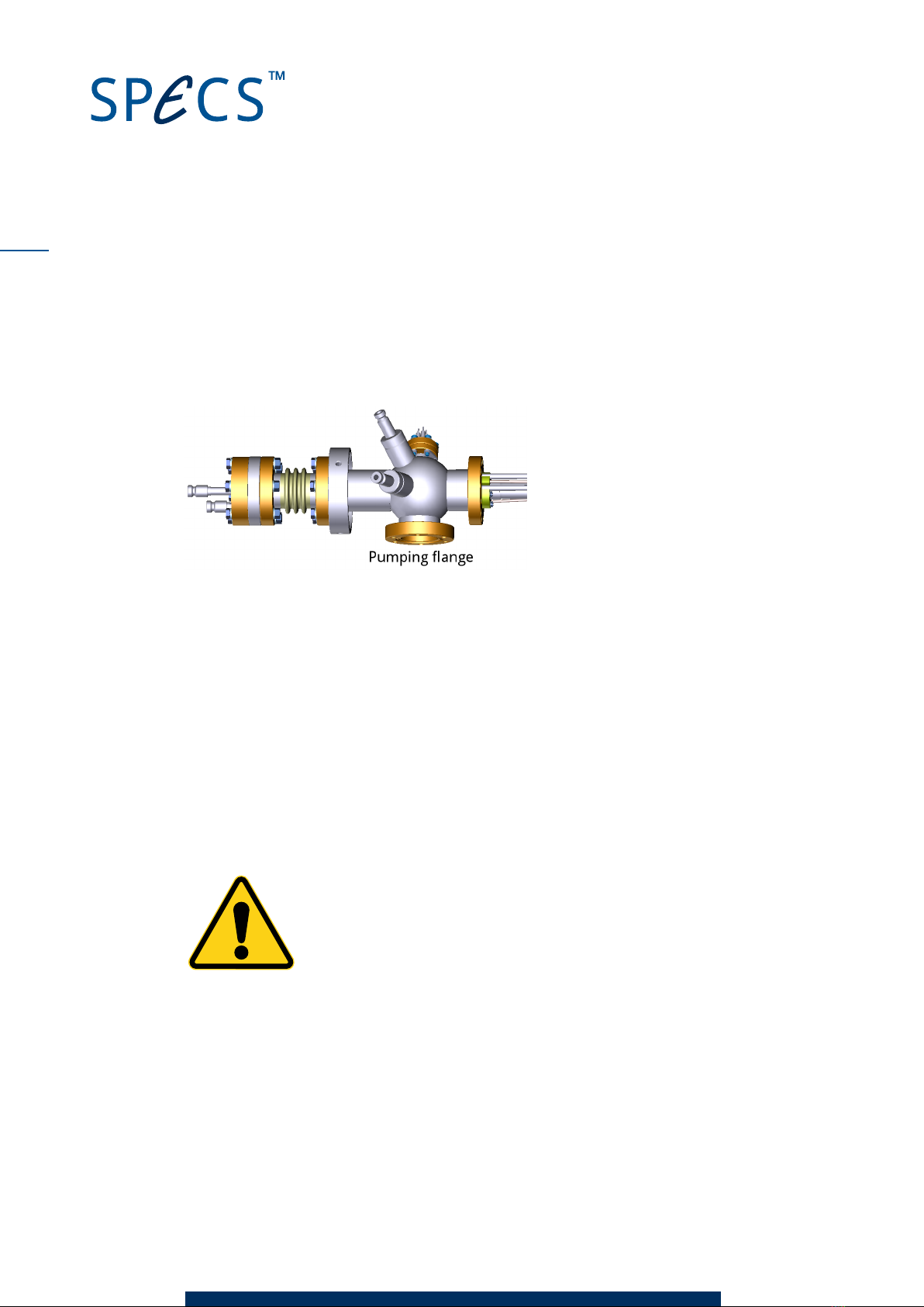
2.2.2 Differential Pumping
You can differentially pump the XR 50. There are several advantages to this:
Better vacuum conditions in the anode volume, especially during bakeout.
Less damage to the source if harmful or aggressive gases are in use.
Reduction of aging effects of the anode and the Al window.
Figure 1: Differential pumping flange
The simplest solution for a bypass is the installation of a flexible bellows between the XR 50
bypass flange and a suitable flange on the vacuum chamber. Depending on your configuration,
you may also want to fit a valve to the bypass line in order to be able to isolate the differential
pumping section from the pumping chamber.
More elaborate bypass systems include either ion getter pumps or turbomolecular pumps,
combined with a valve for simultaneous venting with the main chamber.
When installing the XR 50 with differential pumping, orient the source so that the water con-
nectors face upward.
Caution!
The bypass line must be vented simultaneously together with the main cham-
ber to avoid damaging the Al-window.
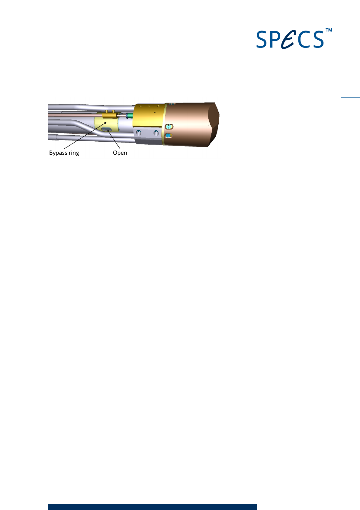
Set the bypass ring shutter on the X-ray source main frame as follows:
Open—if no differential pumping system is installed.
Closed—if a differential pumping system is installed.
6
7
XR 50 V3.1 | May 02, 2016
Figure 2: Bypass ring in the open position
2.2.3 Z-Drive (Optional)
The XR 50 can be supplied with an optional Z-drive so that the source can be retracted from its
working position. This protects the head of the source (and its aluminium window) from dam-
age, e.g. from sputtering, or prevents the source from obstructing other equipment.
Note
The cooling system of the XR 50 is efficient—there is generally no need to retract the XR 50 in
order to reduce thermal strain on other equipment.
The Z-drive is available in 50 mm and 100 mm versions.
In order to prevent collisions between the HV shield and the Z-drive, a spacer is provided. This
is a 40 mm tube with a DN40CF flange at each end, one flange being rotatable. You should
attach the items to the chamber in the following order:
Z-drive
Spacer
Source
2.3 Bakeout
The XR 50 can be baked up to 180 °C. Remember to observe the maximum bakeout tem-
perature for other equipment on your system. Do not use heating tapes or jackets for the
bakeout—these can lead to hotspots which can damage the source and cause uneven baking
conditions which may lead to pressure bursts and arcing during operation.
Before baking out, observe the following points:
Unplug the grounding cables.
Remove the protection cap and supporting frame.
Remove all cables and water connections from the XR 50.
Blow any water out of the source using compressed air.
XR 50 V3.1 | May 02, 2016
Danger—High Voltages Present!
It will take 3 minutes before all high voltages are absent in the system. Wait
at least 3 minutes before disconnecting any cables from the power supply or
the X-ray source.
2.4 Water Cooling
Adequate water cooling is vital for the operation of the XR 50. The electrical connections dia-
gram in Figure 4 on page 11 also shows the necessary water connections. The following sec-
tions provide additional information about the water circuits as well as the basic requirements
for the cooling water.
SPECS supports only the use of water as the cooling agent for the XR 50.
Caution!
The quality of the water supply is critical to the stable and reliable operation
of the XR 50. Please refer to the CCX 70 manual for requirements of the cool-
ing water.
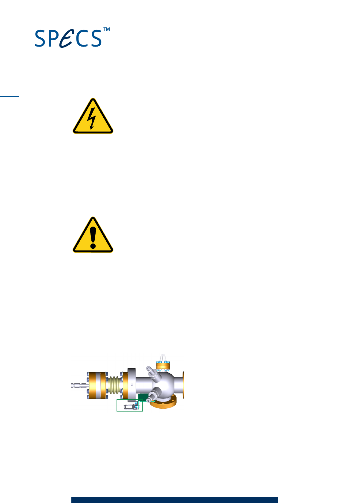
2.4.1 Fitting the Protection Cap
During operation, the top flange of the XR 50 is at high voltage. For safety reasons, a protection
cap prevents access to this flange. A safety interlock switch mounted on the side of the cap is
closed when the cap is correctly in position. The high voltage can only be activated when this
switch is closed.
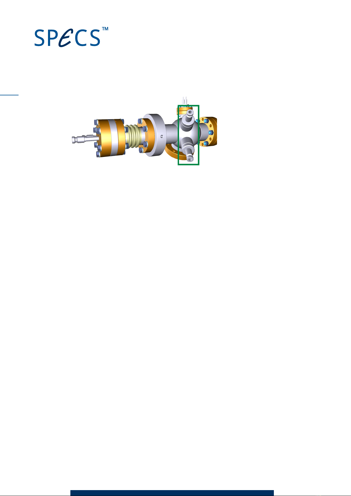
The picture below shows the source head before fitting the protection cap. Note the position of
the safety switch contact (marked with a green box) . You need to use this for orientation of the
protection cap.
To fit the protection cap:
1. Fit the support frame over the source flange and tighten the three grub screws to fix it into
place. This supports the weight of the conduit while connecting the water hoses.
8
9
XR 50 V3.1 | May 02, 2016
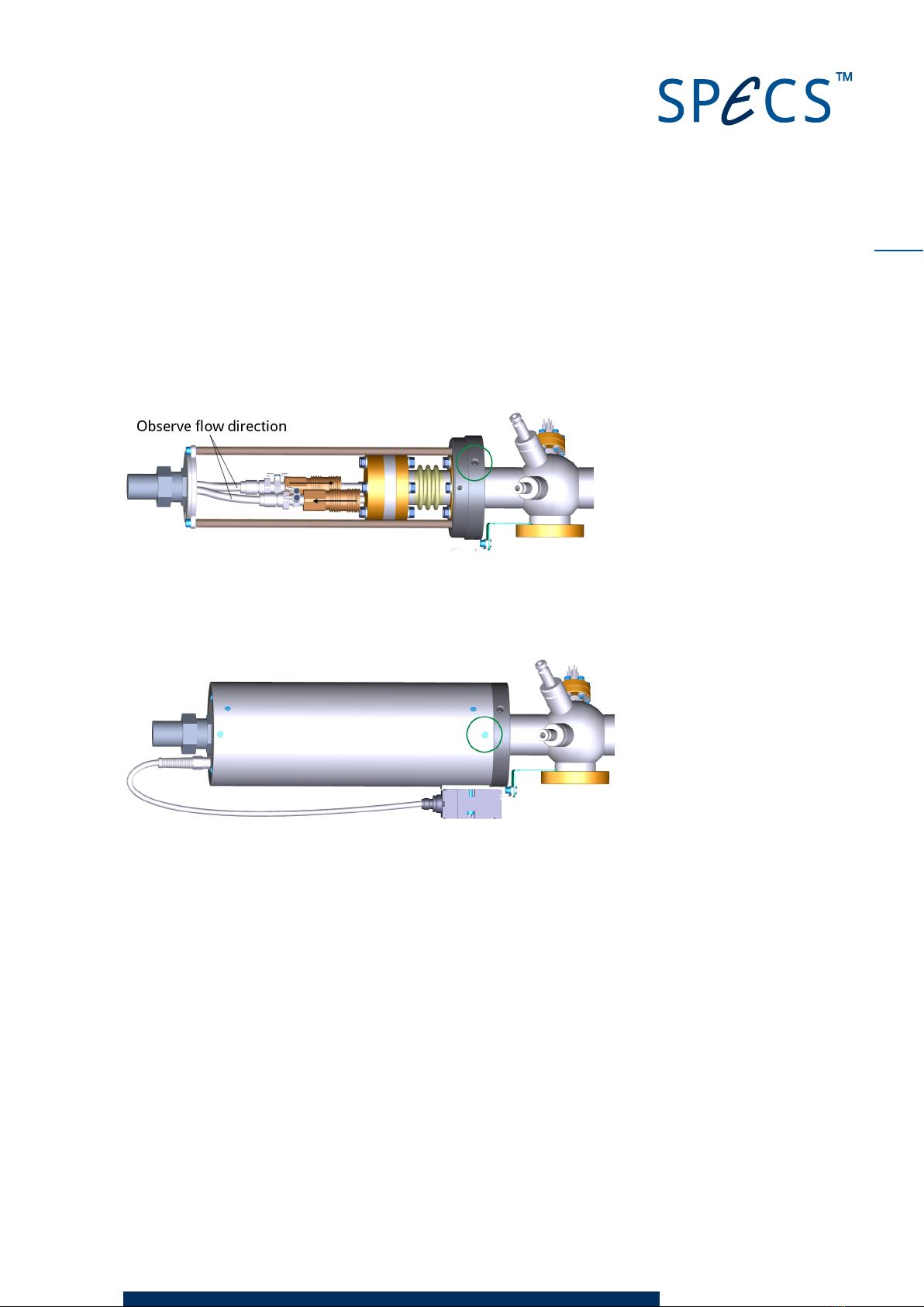
2. Fit the water hoses onto the cooling pipes, making sure to observe the correct flow dir-
ection. The hoses and pipes are labeled with arrows. The center (longer) pipe is for water
flowing into the source.
Note
The high voltage connections are also made when you fit the hoses.
3. Slide the protection cap over the frame so that the contact fits into the safety switch.
4. Secure the protection cap with the three screws around the side of the cap.
Removing the protection cap is the reverse of the above. Note the following points:
When pulling the cap away from the head, take care not to strain the cable for the safety
switch interlock.
Always disconnect the water connectors before removing the support frame. Without the
frame, the weight of the conduit can damage the water hoses.
2.4.2 Head Cooling Circuit
The XR 50 has a second cooling circuit to cool the area around the filament and anode. The
body of the source remains cool, reducing radiative transfer of heat to other components (or
the sample).
Figure 3 shows the location of the head cooling connectors. The direction of flow through this
circuit is not important.
XR 50 V3.1 | May 02, 2016
Figure 3: Head cooling connections
2.5 Connecting Electrical Supplies
The following sections show the electrical connections for the XR 50 as well as a description of
the safety interlocks in the system.
For more information, please refer to the UXC 1000 manual.
2.5.1 Electrical Connections
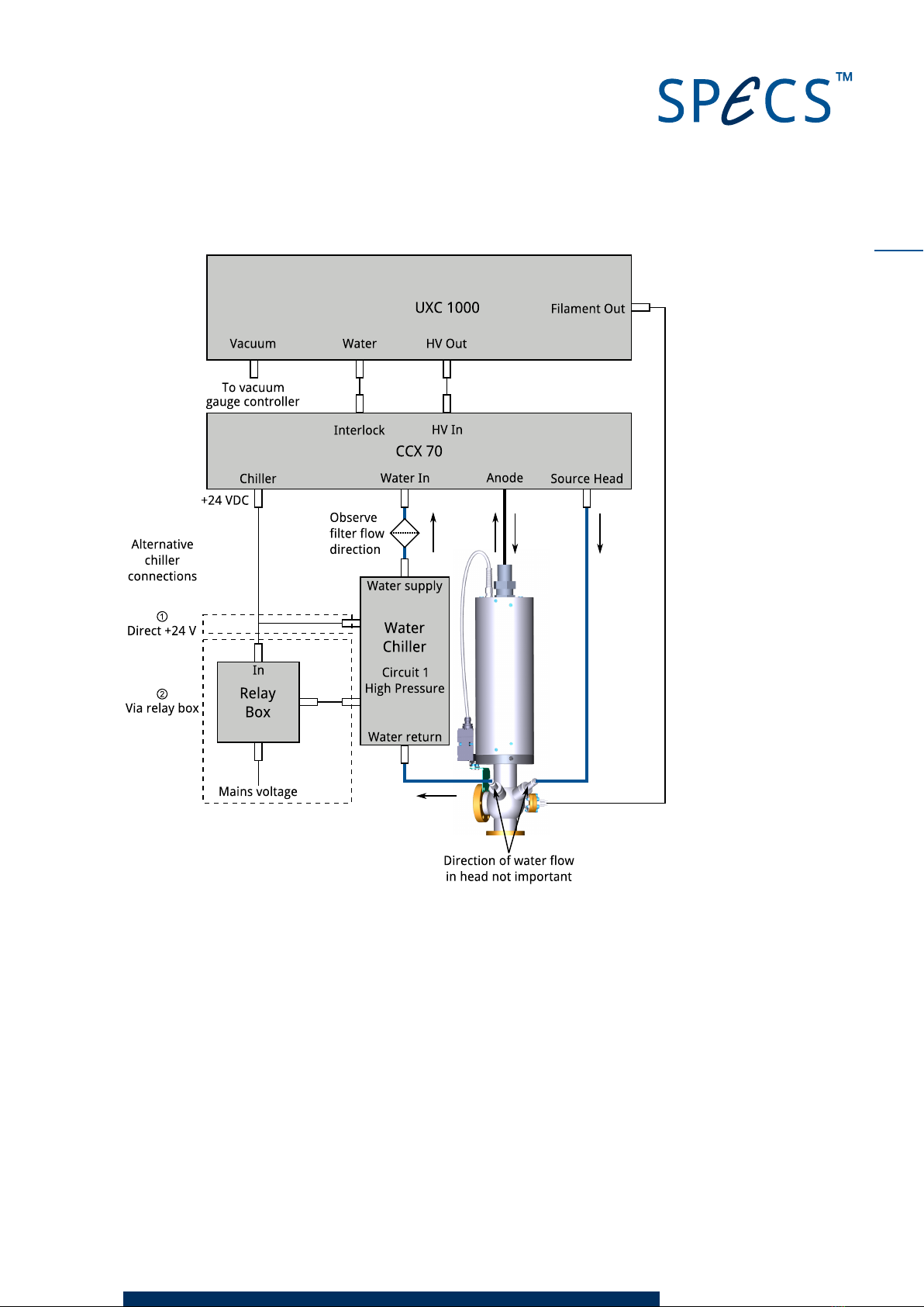
Figure 4 provides an overview of the electrical as well as the water connections for the XR 50.
If you have a water chiller supplied by SPECS, you can set it so that is it automatically switched
on and off by the CCX 70. There are two alternative methods for this connection (see Figure 4):
①Directly to the chiller, using a +24 V input on the chiller.
②Via a relay box, which switches the mains power supply to the chiller.
If you are not using a water chiller, e.g. tap water or another installed water supply, the con-
nection scheme is essentially the same, with your water supply in the place of the water chiller.
10
11
XR 50 V3.1 | May 02, 2016
Figure 4: Electrical and water connections
2.5.2 Interlocks
The XR 50 is protected by a number of interlocks:
Water—sensors inside the CCX 70 monitor the water flow and temperature, sending the
signal to the UXC 1000. If these parameters fall outside the limits set in the UXC 1000,
source operation is stopped.
HV—the HVcable must be plugged into the back of the UXC 1000 before the high voltage
can be activated.
Protection cap—there is a microswitch on the protection cap that is closed when the cap is
correctly fitted. The high voltage can only be activated when this switch is closed.
XR 50 V3.1 | May 02, 2016
Vacuum—the UXC 1000 can be connected to a vacuum gauge measurement controller.
When the pressure interlock trips, the high voltage and filament are switched off. A
bridging connector is provided in case you do not need to use this interlock. Some form of
vacuum interlock is however recommended in order to protect the source from high pres-
sures.
If the XR 50 is correctly connected and the conditions described in this chapter are met, these
interlocks are safe and the XR 50 can be operated.
Caution!
Do not attempt to defeat the interlocks. Death, serious injury or severe dam-
age to the source can result if the interlocks are overridden.
2.6 Anode and Filament Conditioning
After baking out the XR 50, there will still be adsorbates on the working surfaces of the source.
These will cause outgassing and HV discharges when you try to operate the source. The con-
ditioning procedure removes these adsorbates by slowly ramping the source parameters up to
their operating values. By the end of the conditioning, the source should be ready for normal
use.
To condition the filament and anode:
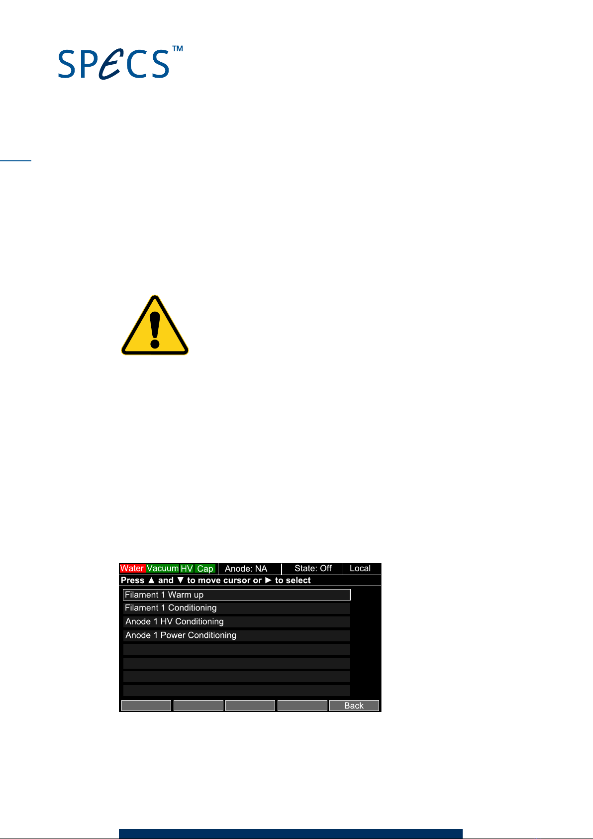
1. Switch on the UXC 1000. A splash screen will appear while the unit starts up. After a short
time. the main menu will appear. A rectangular cursor surrounds the item Anode 1 startup
procedures.
2. Press ►to select the item. The Anode 1 startup procedures menu will appear.
Figure 5: The source startup menu
12
13
XR 50 V3.1 | May 02, 2016
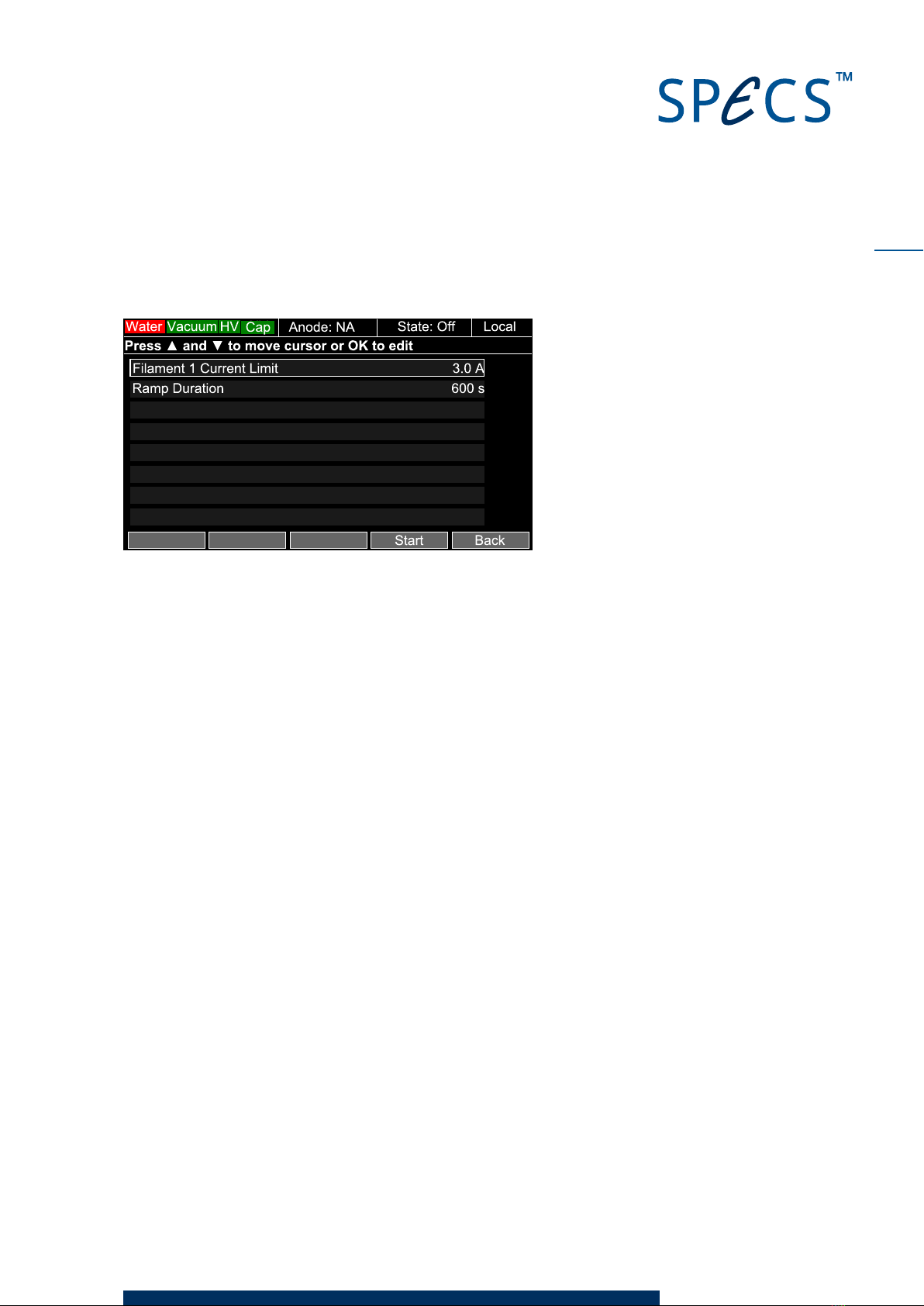
3. Press ▼once to move the cursor down one space to Filament 1 Conditioning and then
press ►to select.
Figure 6: Conditioning the filament
4. Press the
Start
softkey (bottom right key below the display). The UXC 1000 will ramp the fil-
ament up to the current limit shown in the menu over the warmramp time. When it has fin-
ished, a notification will appear.
5. Press
OK
. The screen will return to the Anode 1 startup procedures menu. Note that Anode
1 is now indicated in the top information bar.
6. Press ▼to select Anode 1 HV Conditioning and then press ►.
7. Press the
Start
softkey. The UXC 1000 will ramp the HV up to 15 kV over the ramp time.
When it has finished, a notification will appear.
8. Press
OK
. The screen will return to the Anode 1 startup procedures menu.
Note
Since the two anodes are electrically connected, this procedure also conditions anode 2.
9. Select
Anode 1 Power Conditioning
and then press ►.
10. Press the
Start
softkey. The UXC 1000 will ramp the filament and anode until the preset
maximum power is reached. This completes the conditioning for Anode 1. When it has fin-
ished, a notification will appear.
11. Press
OK
. The UXC 1000 will return to the main menu.
12. Select
Anode 2 Startup Procedures
and press ►to enter the Anode 2 startup procedures
menu.
13. Condition the filament and power for anode 2 in the same way as for anode 1.
Note
As noted above, the HV conditioning applies to both anodes. There is therefore no need to per-
form the Anode 2 HVconditioning if you have already done this for anode 1.

XR 50 V3.1 | May 02, 2016
This page intentionally left
14
This manual suits for next models
1
Table of contents
Popular Laboratory Equipment manuals by other brands

Mind Media
Mind Media NeXus-32 user manual

Isotech
Isotech 17724M User maintenance manual/handbook

PerkinElmer
PerkinElmer Lambda 365 user guide

PerkinElmer
PerkinElmer TITAN MPS user guide

Koehler
Koehler K3919 Series Operation and instruction manual

Roche
Roche MagNA Pure Compact Instrument Operator's manual

Beckman Coulter
Beckman Coulter UniCel DxC 600 Daily start up

Instrutech
Instrutech ITC-1600 user manual

Heidolph
Heidolph Hei-MIX Unimax 2010 operating instructions

PerkinElmer
PerkinElmer Panthera-Puncher 9 user manual

RMG
RMG PGC 9300 Maintenance manual

Teledyne
Teledyne FALCON GC Operation and maintenance manual


