Spectra 1964 C610 User manual

!
1!
Model C610
Operation Manual
Contact Information:
860 West Riverdale Road
Suite D6
Riverdale, UT 84405
801-605-8849
9:00 AM – 5:00 PM MST
WWW.SPECTRA1964.COM
6/1/2019

!
2!
TABLE OF CONTENTS
UNPACKING AND INSPECTION……………………………..…………………………………………3
INTRODUCTION………………………………………………………..…………………………………3
SPECIFICATIONS…………………………………………………..……………………………………..4
QUICK START GUIDE……………………………………………………………………………………5
MODES OF OPERATION………………………………………….……………………………………...8
Principal of Operation
Normal Linear Amplification
Peak Limiting Only
Compression and Limiting Simultaneously
Compression Only
Limiting and Compression with Additional Fixed Amplitude Protection
CONTROL AND MONITOR FUNCTIONS…………………………………………………………….12
Constant Threshold Operating Advantage
No “De-Ess” Roll-Off
Input and Output Level Controls
Slope Control
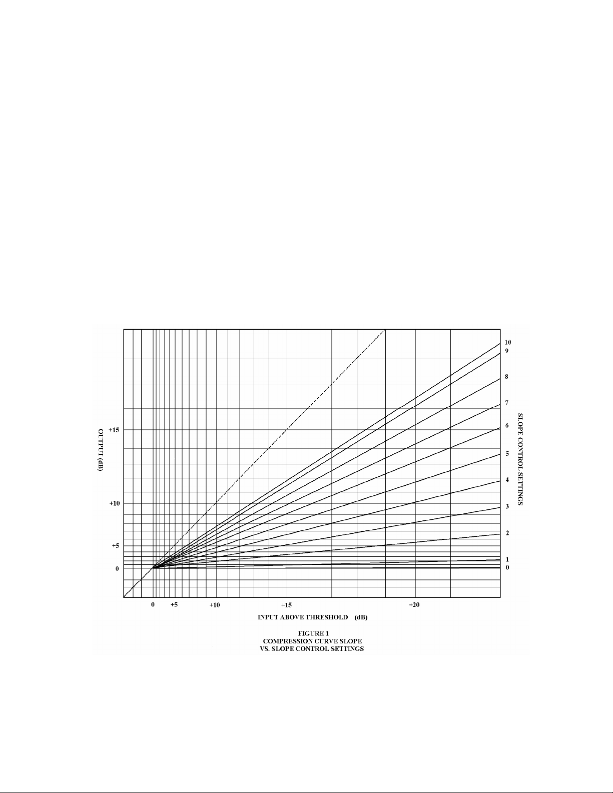
Figure 1: Compression Curve Slope vs. Slope Control Settings
Release Control
Figure 2: Actual Release Time vs. Release Control Settings
Overload Indicator Lamp
Meter Switch
Input Pad
WARRANTY..……………………………………………………………………………………………..16

!
3!
UNPACKING AND INSPECTION
Before accepting the Model C610 “COMPLIMITER” from the shipper, inspect the shipping carton for external
damage. Any sign of external damage must be noted by both customer and shipper, and should be called to the
attention of the insurance investigator. After the equipment is unpacked, inspect the unit for any damage in
shipping. Check for scratches or dents, damaged knobs, or connectors. If damage is noted, do not use the unit
unless instructed by the insuring agency.
NOTICE
The Spectra 1964 Model C610 contains no user serviceable parts. Removal of top or bottom cover plates
shall void product warranty. See warranty section for additional warranty information, page 20.
INTRODUCTION
The Model C610 “COMPLIMITER” is a compressor/limiter system with performance both measurably and
audibly discernible as “beyond the state of the art”. The completely self-contained unit is compatible with the
audio equipment and accessories used in professional recording, broadcasting, motion picture and sound-
reinforcement industries. Because of extremely low noise characteristics of the design, the system has a very
low input level threshold of -40 dBu, thus providing the greatest input sensitivity and compatibility with the
widest range of system levels available on the professional audio market. Depending on the program content,
the Model C610 “COMPLIMITER” will accept an input signal from -50 dBu to -40 dBu just prior to beginning
compression, as well as standard line level input signal.
Control functions are provided on the front panel for input level threshold, continuously variable compression
slope (ratio), release time, selectable pad (10 and 20 dB), and output level. Visual LED indicators for peak
limiting and system overload are provided, in addition to Vu meter monitoring. This manual, as well as the
quick start guide is provided to aid the operator in obtaining maximum performance from the Model C610
“COMPLIMITER”. READ THE INSTRUCTION MANUAL, especially the QUICK START GUIDE, before
using the unit.

!
4!
SPECIFICATIONS
Input Impedance……………………..………………………………………………….2.4 kOhms nominal
Output Impedance………………………..……….......Approximately 120 ohms (1kHz), floating
Output Loading………………………..…………...600 ohms to Infinity, balanced or unbalanced
Maximum Gain……………………………………………..………………………………..56 dB
Input Level………………………………..…………………………Typically -50 dBu to +10 dBu
Threshold Attack Level………………………………………..…………………………-40 dBu
Output Level………………………..…………………………………Typically +4 dBu or +8 dBu
Signal-to-Noise Ratio……………………...…..Not less that 80 dB below +4 dBu output with -40
dBu input (threshold), 20 Hz to 20 kHz, unweighted.
Frequency Response……………………..…. ± .1 dB, 20 Hz to 40 kHz, at +16 dBu (High Z load)
± .5 dB, 20 Hz to 20 kHz, at + 16 dBm (600 ohm load)
Harmonic Distortion………………….…..…….Less than 1/10th of 1%, 30 Hz to 20 kHz, at +16
dBu, up to 30 dB compression, with release time such that attack
and release does not occur on successive peaks of the lowest
frequency utilized. (Typically less than 5/100ths of 1%)
Compression/Limiting Ratio......................Continuously variable from approx. 1.1:1 to 100:1
Attack Time………………………………………………………………..Automatically Variable
Limiter……………………………………………….100 nanoseconds to 2.0 microseconds
Compressor…………………………………………...100 nanoseconds to 1.2 milliseconds
Release Time……………………………………………………………………For 90% Recovery
Limiter…………………………………………………………..Less than 90 nanoseconds
Compressor…………Continuously variable from 50 milliseconds to more than 10 seconds
Maximum Temperature…………………………………………………..140 degrees Fahrenheit
Power Supply………………………………………………….Universal 120-240 VAC, 50/60 Hz, 6 watts
Physical Dimensions…………….3 1/2” high x 19”wide x 4 1/4” deep for standard rack mounting
Weight………………………………………………………Net, 3 1/2 pounds, Shipping, 9 pounds
Stereophonic Interconnection……………………………..Requires standard 1/4" TRS cable

!
5!
The C610 Quick Start Guide
(1.) Input Level Control
PROPER SETUP OF THIS CONTROL WILL ALLOW FOR CONSISTENT AND REPEATABLE PERFORMANCE
The C610 compressor circuit is designed to operate levels of -40dBu or greater. The input level control allows for adjustment to attain
-40dBu level. As gain is increased beyond the -40dBu input level, resulting compression follows incrementally. The amount of input
level compression may be readily viewed on the C610 meter by selecting the gain reduction setting,(GR), located on the front panel.
In gain reduction mode, the meter will deflect right to left, thus indicating the amount of gain reduction, in dBu. Adjusting the input
level will give a visual demonstration as to the relation of input gain versus gain reduction.
The C610 is capable of signal levels 30dBu above the -40dBu input reference level, (-10dBu). Levels beyond this reference standard
may be easily attenuated with the input level control.
Stereophonic Operation
The interconnection couples the attack and release action of the limiting and compressing functions of the two units. The input
(compression/limiting) and slope controls on either unit may be independently set for the desired mode of operation. However, when
the attack action of either unit is activated, the other will follow so as to maintain the stereophonic perspective. The release action will
follow the fastest setting on either unit. Prior to differing applications, the accessory may be switched in or out of the circuit as
desired.
¼” TRS cable required for two channel operation.
Independent Peak Limiting/Compression
A unique and important design feature of the C610 is to eliminate the "peak" transient information independent of the compression
function. Audio program peaks, as defined by Spectra 1964 over four decades ago, operate at frequencies well beyond 20 kilohertz
and contain no music program material. Conversely, conventional analog peak limiter circuits that operate in the 20-kilohertz range
will affect program material content in terms of frequency response, distortion and headroom.
In addition, the compression function on conventional analog compressors will be determined by peak content. The greater the
peak/average ratio, the greater the compression and loss of dynamic range and increase in system noise.
The C610 eliminates the peaks and allows for improved dynamic range and system noise by increased compressor gain.
Peak Limiting Only
For maximum dynamic range, and no compression, this configuration is required:
-Set the input level whereby the "threshold" LED occasionally flashes. The "threshold" LED should not be illuminated on a constant
basis. This setting indicates at peaks only. The "threshold" circuit is like no other in the industry and operates an extremely high
frequency similar to an oscilloscope.
-Set the meter to "GR" (gain reduction). The meter should not indicate any gain reduction (compression). The output knob may be
used to increase gain as required.

!
6!
Compression and Limiting Simultaneously
For both compression and limiting of audio program material whereby dynamic range can be maximized as well as elimination of
audio program peaks.
-With the meter set at "GR", gain reduction, increase input level until Vu meter indicates gain reduction, (indicator needle moves right
to left). At this input level, the "threshold" LED will be illuminated intermittently and not occasionally flicker.
-The amount of compression will be determined by the input level control setting. A visual representation, using the "GR", (gain
reduction), setting should be readily apparent.
-This mode is used whenever a small to intermediate amount of compression is desired.
Compression Only
When the average level of the input signal to the C610 is continually above the full illumination "threshold" level, then compression
only occurs.
- Under this mode only "GR", gain reduction occurs, (under this condition, longer release times are recommended.)
(2.) Output Level Control
The C610 utilizes two independent modules/circuits for audio signal compression and gain.
The compressor limiter function is controlled by the Model 601 Complimiter module.
It is important that the user understands the relationship between input level, (gain), and output level.
Improper level adjustment can result in loss of dynamic range and possibly increased system distortion.
The C610 Complimiter has a gain of 56dB. Of the total, approximately 40dB of gain is provided by the second, 101 amplifier module.
The sole purpose of the 101 module is to make-up gain for the C610. The output knob of the C610 controls the 101 module gain. If the
input gain is set at -40dBu as described earlier, then the amount of undistorted gain available is 56dB with 1.1-1 compression. This is
referenced at+16dBu maximum output, and indicated via the red overload indicator on the C610. Decreases in gain will result as
compression is increased.
(3.) Threshold
A flashing LED indicates transients, (peaks), at -40dBu and below. A constant LED indicates -40dBu and above for program material.
The threshold circuit operates at high frequencies well beyond conventional peak indicators. As a result, the C610 will indicate peak
amplitude material without the use of a specialized measurement device.
(4.) Overload
The red overload indicator LED will illuminate whenever excessive input or output signal level overload, (+16 dBu), occurs. In some
applications it is particularly desirable to utilize the overload indicator LED as a guide to obtaining additional limiting with the output
of the Model C610 Complimiter.

!
7!
(5.) Release Control
The release control knob affects the signal release time after initial signal compression.
Maximum release time, marked "10" on the front panel, will slowly restore gain to the original level. Long release times are often used
for multiple source program material, main program channel material, mastering, or very slow source material from a single source.
(6.) Slope Control
The slope control provides the widest range of compression/limiting ratios available, from 1.1:1 to 100:1. When the slope control is
set for minimum compression, the knob is set at "10", thus providing peak limiting and linear amplification of 20dBu. When the slope
is set for maximum compression, the knob is set at "0", for a flat slope of up to 100:1.
(7.) Meter Switch
A three position rotary switch is provided for selection of the VU metering between gain reduction and two output reference levels.
When set to "GR" the VU meter indicated the amount of gain reduction, (compression). When set to "+4" or "+8" and the VU meter is
monitoring the output signal level, 0 VU on the VU meter corresponds to +4 dBu or +8 dBu.
(8.) Input Pad
Selectable S1 Analog dBu Input Level Range
S2 Digital dBFS Input Level Range

!
8!
Termination of the C610
The C610 utilizes ultra-high quality input and output transformers. The unit may be terminated to unbalanced or balanced audio
equipment. Please note that the C610 is a professional low impedance device.
The C610 is transformer balanced for the input and output sections of the device. For unbalanced operation, combine pin 1 (shield),
with pin 3, signed minus (-). Pin 2 is signal plus (+).
MODES OF OPERATION
Principal of Operation
The Model C610 “COMPLIMITER” is the first compressor/limiter that allows the professional the widest range
of separate and distinct modes of operation. The attainment of this flexibility is based upon being able to easily
and precisely set the input and output level controls. This is a result of interaction among the following
principals of operation:
1. Accurate monitoring of peak vs. average input signal levels using visual “threshold” LED indication and
Vu meter, respectively.
2. Constant threshold attack level for any compression slope setting.
The following modes of operation result from interaction of the above principles and are recommended for
actual use to demonstrate the simplicity of obtaining both maximum performance and maximum versatility with
the Model C610.
1. Normal linear amplification.
2. Peak limiting only (maximum level below fixed amplitude without affecting dynamic range).
3. Compression and limiting simultaneously.
4. Compression only.
5. Limiting and compression with additional fixed amplitude protection, (maximum percent modulation).
Through variations of these separate and distinct modes of operation, innumerable audio signal combinations
are obtainable. For each mode of operation there follows an explanation of the interaction of the principals of
operation, control settings and typical applications.
Normal Linear Application
This mode of operation always occurs when both the average and peak level of the signal waveform are below
the threshold attack level of -40 dBu. Since neither the compression nor limiting functions of the Model C610
will be activated, the slope control and release time settings will have no effect on the output, and 20 dB of
normal linear amplification will be provided. In addition, whenever the slope control is set to the minimum
compression/limiting ratio of 1.1 to 1 (“10” slope control setting = fully clockwise), normal linear amplification
occurs for all input signal levels above the -40 dBu threshold attack level. This latter condition of operation
above the threshold attack level provides the maximum signal-to-noise ratio for the device.
!

!
9!
Microphone!and!Line!Level!Settings!
Control!settings:!For!low!signal!levels!(e.g.!Microphone,!etc.),!no!attenuation!of!the!input!signal!is!
required!and!the!threshold!attack!LED!will!occasionally!flash!whenever!input!levels!are!above!threshold.!
For!higher!signal!levels!(e.g.!Line,!etc.),!it!is!preferable!to!operate!above!the!point!of!threshold!and!thus!
maximize!the!signal-to-noise!ratio!of!the!system.!The!slope!control!is!set!to!approximately!normal!linear!
amplification!(“10”!slope!control!setting!=!fully!clockwise),!the!release!control!setting!is!not!critical!and!
may!be!set!at!maximum!time.!The!input!level!control!is!adjusted!so!the!threshold!attack!LED!is!
continually!illuminated.!For!either!of!these!two!conditions,!adjust!the!output!level!control!to!obtain!the!
level!required.!
Typical!Application:!This!mode!provides!amplification!for!input!signal!levels!below!the!-40!dBu!
threshold!attack!level,!such!as!when!normal!microphone!output!levels,!(-50dBu),!are!terminated!directly!
to!the!Model!C610.!For!higher!level!input!signals,!setting!the!slope!control!to!approximately!normal!linear!
amplification!has!the!practical!equivalent!of!switching!the!Model!C610!out!of!the!circuit.!
Peak!Limiting!Only!
For!all!levels!of!the!input!signal!waveform!where!peak!signals!are!above!threshold,!and!average!
level!is!below!threshold,!peak!limiting!occurs.!
Peak!waveforms!or!transients,!by!definition,!are!high!amplitude,!short!time-base,!and!are!beyond!the!
audible!range,!(20!kHz).!Thus,!the!independent!limiting!function!will!attack,!instantaneously,!to!provide!
complete!peak!overload!protection.!The!limiting!curve!approximately!follows!the!compression!curve!and,!
a!continuously!variable!limiting!curve!is!obtainable.!For!positive!amplitude!protection,!a!flat!compression!
slope!provides!a!flat!limiting!protection!line.!
Control!Settings:!Increase!the!input!level!control!until!the!threshold!attack!LED!occasionally!begins!to!
flash,!indicating!peaks!are!beginning!to!cross!threshold.!The!control!setting!will!approximately!represent!
the!maximum!amplitude!of!the!peak!material!for!this!audio!program!selection.!The!maximum!amount!of!
peak!limiting!will!occur!just!prior!to!the!point!where!the!VU!meter!begins!to!indicate!gain!reduction.!The!
slope!control!is!set!for!minimum,!(flat),!slope!of!the!limiting,!(and!compression),!curve!(fully!clockwise).!
Since!compression!is!not!being!activated,!the!release!control!setting!is!not!critical!and!would!be!set!for!
maximum!release!time,!(fully!clockwise).!Adjust!the!output!level!control!to!obtain!the!level!required.!
Typical!Application:!Maximum!Vu!output!without!affecting!dynamic!range!is!obtained!without!
maximum!peak!limiting.!With!no!compression!of!audio!program!source!material,!no!peak!program!
material!will!be!transferred!through!the!Model!C610,!thus!allowing!improved!audio!level.!As!a!result,!
increased!headroom!will!be!realized!without!associated!“peak!overload”,!(typically!10dB).!In!addition,!an!
improvement!in!signal!to!noise!ratio!will!be!achieved!in!proportion!to!the!increase!in!signal!level.!
!
!
!
!

!
10!
Compression!and!Limiting!Simultaneously!
This!mode!of!operation!occurs!when!the!average!level!continually!alternates!above!and!below!the!
constant!threshold!attack!level.!
When!the!audio!program!waveform!initially!crosses!threshold,!the!limiter!will!attack!and!hold!until!the!
compression!function!takes!over.!The!cycle!will!repeat!each!time!the!average!level!crosses!the!threshold.!
The!compression!slope!does!not!change!the!threshold!attack!level!or!the!threshold!indication.!The!release!
time!will!determine!how!long!the!function!will!hold.!
Control!Settings:!Increase!the!input!level!control!until!the!Vu!meter!begins!to!indicate!compression.!The!
threshold!attack!LED!indicator!will!be!illuminated!continuously!since!the!average!signal!level!will!now!be!
above!threshold.!The!amount!of!additional!compression!is!dependant!upon!the!input!level!control!setting.!
When!the!release!control!is!set!for!the!shortest!release!time,!maximum!average!level!will!be!obtained!
with!an!increase!in!audio!level!and!distortion.!Longer!release!time!will!provide!the!smoothest!action!with!
minimum!audio!level!changes,!minimum!distortion!and!average!level!slightly!lower!than!the!maximum.!
Adjust!the!output!level!control!to!obtain!the!level!required.!
Typical!Application:!This!mode!is!used!whenever!a!small!or!intermediate!amount!of!compression!is!
desired.!!
Compression!Only!
When!the!average!level!of!the!input!signal!to!the!compressor/limiter!is!continually!above!the!threshold!
attack!level,!this!mode!occurs.!
Control!Settings:!Increase!the!input!level!control!until!the!Vu!meter!continually!reads!compression!and!
the!threshold!lamp!is!continually!illuminated.!Generally,!longer!release!times!should!be!used.!
Typical!Application:!Wherever!a!large!amount!of!compression!is!required,!operate!in!this!mode.!
Limiting!and!Compression!with!Additional!Output!Limiting/Broadcast!Application!
This!mode!is!the!same!as!the!previous!“Compression!and!Limiting!Simultaneously”!mode,!except!that!
additional!amplitude!protection!at!a!fixed!level!is!provided!by!driving!the!output!amplifier!to!maximum!
output,!(peak!clipping).!
The!system!provides!“limiting-on-limiting,”!which!assures!maximum!power!output!or!maximum!percent!
modulation.!When!utilized!in!this!manner,!an!external!pad!after!the!Model!C610!is!needed!to!reduce!the!
higher!output!level!to!line!level.!
The!red!overload!lamp!indicator!is!set!to!illuminate!for!output!amplifier!signals!of!approximately!+17!
dBu,!well!in!advance!of!the!actual!output!amplifier!limiting!of!+18!dBu!or!greater.!Under!normal!
circumstances,!this!is!the!preferred!operation.!However,!additional!precise!laboratory!lamp!indication!at!
the!point!of!output!amplifier!limiting!may!be!preferred.!Calibration!of!the!overload!light!for!this!function!
is!available!at!a!nominal!charge!from!the!factory.!
!

!
11!
Control!Settings:!Set!the!controls!in!the!same!manner!as!described!in!the!previous!“Compression!and!
Limiting!Simultaneously”!mode!except!that!the!output!level!control!should!be!set!so!the!red!overload!
lamp!begins!to!flash.!Thus,!a!final!fixed!amplitude!protection!line!is!provided!to!prevent!subsequent!
overload!distortion,!over-modulation,!etc.!
Typical!Applications:!This!mode!is!particularly!applicable!to!broadcast!applications!where!a!maximum!
percentage!of!modulation!is!required.!A!resistance!in!series,!(e.g.!600!ohms,!1000!ohms!potentiometer,!
etc.)!where!signal!output!is!sufficient!to!pad!the!signal!positive!down!to!standard!+8!dBm!broadcast!line!
(e.g.!600!telephone!lines!etc.)!level.!This!mode!may!be!used!for!any!application!where!maximum!level!is!
to!be!obtained!without!crossing!above!a!maximum!amplitude!protection!line.!
!
!
!
!
!
!
!
!
!
!
!
!
!
!
!
!

!
12!
!
CONTROL!AND!MONITOR!FUNCTIONS!
Constant!Threshold!Operating!Advantages!
The!constant!threshold!attack!level!provides!a!significant!operating!advantage!by!eliminating!the!need!to!
continually!reset!the!input!level!for!each!new!variation!of!compression!ratio.!Thus,!comparison!analysis!
on!simplified!“A-B”!basis!is!possible!and!the!selection!of!the!desired!slope!of!the!compression!curve!is!
easier,!more!accurately!determined,!and!requires!less!time.!
No!“De-Ess”!Roll-Off!
The!need!for!“de-ess”!or!“de-emphasis”!has!been!eliminated!through!the!advanced!design!dual!function,!
independent!compression!and!limiting!of!the!Model!C610.!Conventional!single!function!analog!
compressor/limiters!are!not!capable!of!reacting!in!time!to!protect!against!higher!frequency!sibilant!
sounds!without!markedly!sacrificing!the!performance!of!audio!program!material.!Considerable!
engineering!design!effort!was!required!to!develop!a!sophisticated!dual!function!system.!“De-ess”!or!“de-
emphasis”!controls!frequencies!irrespective!of!whether!or!not!transients!or!sibilant!peaks!are!present.!
The!professional!audio!engineer!is!no!longer!in!control!of!the!final!program!output!from!such!competitive!
conventional!units!due!to!either!“roll-off”!of!all!high!frequencies!to!avoid!sibilant!distortion!from!only!a!
few!high!frequencies,!or!tolerate!sibilant!distortion!from!high!frequency!peak!overload.!
THE!FREQUENCY!RESPONSE!OF!THE!MODEL!C610!DOES!NOT!CHANGE!UNDER!
NORMAL!LINEAR!AMPLIFICATION,!LIMITING!AND/OR!COMPRESSION.!
Input!and!Output!Level!Controls!
THE!INPUT!CONTROL!REGULATES!THE!AMOUNT!OF!COMPRESSION/LIMITING!DESIRED.!The!system!is!
capable!of!receiving!input!signals!30!dB!above!the!constant!threshold!attack!level!without!degradation!in!
performance.!The!output!control!regulates!the!system!output!level!and!is!located!after!the!
compression/limiting!plug-in!module!and!before!the!final!amplifier!plug-in!module.!Continuously!
variable!control!of!the!input!and!output!signal!levels!is!provided!to!allow!any!value!of!attenuation.!The!Vu!
meter!may!be!used!to!monitor!accurately!this!attenuation.!
Slope!(Compression/Limiting!Ratio)!Control!
The!Model!C610!provides!both:!
1. The!widest!range!of!compression/limiting!ratios!–!from!approximately!1.1:1!(approaching!linear!
amplification)!to!100:1!(flat!slope).!
2. Continuously!variable!selection!of!compression!ratios!–!which!may!be!changed!during!use!to!
obtain!any!desired!slope!of!the!compression!curve!without!producing!transients,!pops,!clicks,!etc.,!
or!changing!the!threshold!attack!level.!
For!inputs!up!to!the!point!of!threshold!(-40!dBu),!the!compressor/limiter!provides!20!dB!of!gain.!
Thereafter,!the!output!is!dependant!upon!the!compression/limiting!ratio!selected.!The!unit!
!
13!
restricts/limits!any!program!material!from!exceeding,!in!amplitude,!the!selected!compression/limiting!
ratio!curve.!Distortion!and!gain!decreases!as!the!compression/limiting!ratio!is!reduced!from!the!extreme!
flat!setting.!
When!the!slope!control!is!set!to!the!maximum!compression/limiting!ratio!of!approximately!100!to!1!(“0”!
slope!control!setting!=!fully!counterclockwise),!the!compression/limiting!curve!is!flat.!Hence,!the!
maximum!amplitude!output!is!held!to!a!constant!-20!dBu!for!any!input!level!up!to!30!dB!above!threshold.!
This!extremely!flat!slope!is!very!useful!whenever!a!positive!protection!line!limit!is!required.!
Conversely,!when!the!slope!control!is!set!to!the!minimum!compression/limiting!ratio!of!approximately!
1.1:1!(“10”!slope!control!setting!=!fully!clockwise),!the!slope!of!the!compression!curve!approaches!the!
linear!amplification!curve.!The!Model!C610!approximates!the!operation!of!a!normal!linear!amplifier,!and!
provides!approximately!20!dB!of!gain!for!input!above!threshold.!
For!typical!intermediate!slope!control!settings,!refer!to!Figure!1,!Compression!Curve!Slope!vs.!Slope!
Control!Settings.!For!slope!control!settings!of!approximately!“5”!(50%!open),!a!signal!input!increase!of!15!
dB!above!threshold,!will!increase!the!output!approximately!7.5!dB,!which!is!a!2:1!compression/limiting!
ratio.!
!
!
!
!
14!
Release!Control!
The!continuously!variable!release!time!control!regulates!only!the!compressor!release!function.!
Distortion!is!a!function!of!release!time!and!the!amount!of!compression/limiting.!
Maximum!release!time!(“10”!on!the!panel,!fully!clockwise)!will!slowly!restore!gain!back!to!its!original!
level.!For!lowest!distortion!and!smoothest!response,!the!release!time!should!be!at!least!an!order!of!
magnitude!greater!than!the!time!of!one!cycle!of!the!lowest!frequency!to!be!processed.!Longer!release!
time!settings!are!often!used!for!multiple!source!program!material,!main!program!channel!material,!
mastering,!or!very!slow!music!from!a!single!source.!!
!
Minimum!settings!of!release!time,!(“0”!on!the!panel,!fully!counterclockwise),!will!quickly!restore!gain!
back!to!its!original!level.!For!maximum!average!level!below!a!fixed!amplitude!output,!the!release!control!
should!be!set!at!the!shortest!time;!however,!distortion!and!level!change!variations!will!be!greater.!
Minimum!release!times!are!often!used!for!single!source,!vocal!or!solo!source!material!with!low!
background!noise!and/or!low!background!program!material.!As!the!background!level!increases,!the!quick!
release!to!normal!level,!(short!release!time),!will!be!audibly!detectible!as!a!rapid!change!in!background!
program!level.!
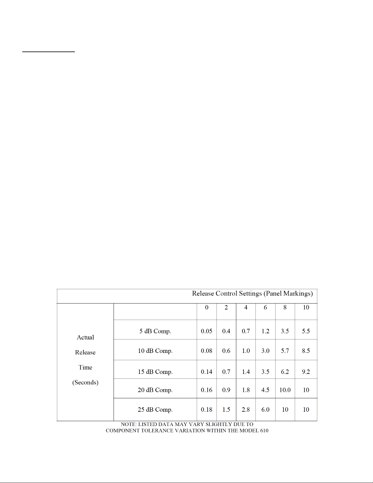
Figure!2,!Actual!Release!Time,!(90%!signal!recovery)!vs.!Release!Control!Settings,!illustrates!the!wide!
degree!of!continuous!release!time!variation!available.!In!addition,!all!the!release!times!may!be!reduced!if!
required.!Please!consult!the!factory!for!adjustment!procedures.!
FIGURE!2!
ACTUAL!RELEASE!TIME!VS.!RELEASE!CONTROL!SETTINGS!
!
!

!
15!
!
In!summary,!the!optimum!release!control!setting!for!maximum!level!below!fixed!amplitude!will!
be!the!shortest!possible!release!time!commensurate!with!the!minimal!amount!of!distortion!
and/or!level!changes.!Judicious!listening!and!selection!of!release!times!for!various!program!
selections!is!recommended,!using!this!information!as!a!guide!
Threshold!Attack!Indicator!LED!
The!Vu!meter!needle!mechanism!cannot!respond!to!instantaneous!peak!limiting!of!the!Model!C610!
system!on!high!amplitude,!short!time!base!transients.!A!Vu!meter!is!capable!of!indicating!longer!time!
base!signal.!When!illuminated,!the!white!threshold!attack!LED!indicates!that!audio!signal!(e.g.!transients,!
peak!program!material,!etc.)!have!crossed!the!constant!-40!dBu!threshold!attack!level!of!the!Model!C610.!
The!frequency!of!the!illumination,!(e.g.!flash,!flashing,!steady,!etc.)!from!the!LED!indicator!gives!the!user!
an!approximate!representation!of!the!peak!limiting!taking!place,!without!the!task!of!monitoring!with!an!
auxiliary!oscilloscope.!
If!the!input!signal!remains!above!threshold!for!a!longer!time,!the!threshold!attack!indicator!LED!will!
remain!illuminated!and!the!Vu!meter,!(meter!switch!set!to!“GR”),!will!indicate!the!amount!of!GAIN!
REDUCTION,!(compression),!that!will!automatically!occur.!
Overload!Indicator!LED!
The!red!overload!indicator!LED!will!illuminate!whenever!excessive!input!or!output!signal!level!overload,!
(+16!dBu),!occurs.!
In!some!applications!it!is!particularly!desirable!to!utilize!the!overload!indicator!LED!as!a!guide!to!
obtaining!additional!limiting!with!the!output!of!the!Model!C610.!
Meter!Switch!
A!three!position!rotary!switch!is!provided!for!selection!of!the!Vu!metering!between!gain!reduction!and!
two!output!levels.!When!set!to!“GR”!the!Vu!meter!indicates!the!amount!of!gain!reduction,!(compression).!
When!set!to!“+4”!or!“+8”!and!the!Vu!meter!is!monitoring!the!output!signal!level,!0!Vu!on!the!Vu!meter!
corresponds!to!+4!dBu!or!+8!dBu,!respectively.!
Input!Pad!
Selectable!10/20!dB!input!pad.!
!
!
!
!
!

!
16!
!
!
!
!
EQUIPMENT!WARRANTY!
The!following!warranty!is!effective!for!all!Spectra!1964,!LLC!(Manufacturer)!products.!Spectra!1964!warrants!that!this!product!
is!free!of!defects!in!both!materials!and!workmanship.!Should!any!part!of!this!product!be!defective,!the!Manufacturer!agrees!at!
its!option,!to:!
A.!Repair!or!replace!with!a!like!new!replacement!any!defective!part!free!of!charge!(except!transportation!charges)!for!a!period!
of!one!year!for!all!products.!This!warranty!period!begins!on!the!date!the!end!user!is!invoiced!for!the!product,!provided!the!end!
user!provides!proof!of!purchase!that!demonstrates!that!the!product!is!still!within!the!warranty!period!and!returns!the!product!
within!the!warranty!period!to!Spectra!1964,!LLC,!according!to!the!Product!Return!and!Repair!Policy!set!forth!below.!All!
inbound!shipping!costs!are!the!responsibility!of!the!end!user;!Spectra!1964,!LLC!will!cover!all!outbound!shipping!costs.!
!
Product!Return!and!Repair!Policy!
Return!to!Manufacturer!
1. An!RMA!(return!merchandise!authorization)!number!must!be!obtained!by!the!end!user!from!Spectra!1964,!LLC.!
2. The!user!must!return!the!product!to!Spectra!1964,!LLC!with!proof!of!purchase!(showing!purchase!date)!for!a!
warranty!claim,!and!display!the!RMA!number!on!the!outside!of!the!shipping!package.!
THIS!WARRANTY!IS!VOID!IF:!
• The!product!has!been!damaged!by!negligence,!accident,!act!of!God,!or!mishandling,!or!has!not!been!operated!in!
accordance!with!the!procedures!described!in!the!operating!and!technical!instructions,!or!
• The!product!has!been!altered!or!repaired!by!other!than!the!Manufacturer!or!an!authorized!service!representative!of!
the!Manufacturer;!or!
• Adaptations!or!accessories!other!than!those!manufactured!or!provided!by!the!Manufacturer!have!been!made!attached!
to!the!product!which,!in!the!determination!of!the!Manufacturer,!shall!have!affected!the!performance,!safety!or!
reliability!of!the!product;!or!
• The!product’s!original!serial!number!has!been!modified!or!removed.!
NO!OTHER!WARRANTY,!EXPRESSED!OR!IMPLIED,!INCLUDING!WARRANTIES!OF!MERCHANTABILITY!OR!FITNESS!FOR!ANY!
PARTICULAR!USE,!APPLIES!TO!THE!PRODUCT.!MANUFACTURER’S!MAXIMUM!LIABILITY!HEREUNDER!SHALL!BE!THE!
AMOUNT!PAID!BY!THE!END!USER!FOR!THE!PRODUCT.!
No!person!or!entity!authorized!to!assume!any!obligation!or!other!liability!in!connection!with!the!products.!No!action,!
regardless!of!form,!arising!out!of!or!relating!to!the!product!or!this!warranty,!may!be!brought!by!end!user!more!than!one!(1)!
year!after!the!cause!of!action!has!accrued.!
Manufacturer!shall!not!be!liable!for!punitive,!consequential,!or!incidental!damages,!expenses,!or!loss!of!revenue!or!property,!
inconvenience,!or!interruption!in!operation!experienced!by!the!end!user!due!to!a!malfunction!in!the!purchased!product.!No!
warranty!service!performed!on!any!product!shall!extend!the!applicable!warranty!period.!
In!case!of!unsatisfactory!operation,!the!end!user!shall!promptly!notify!the!Manufacturer!at!the!address!set!forth!below!in!
writing!or!call!(801)!605-8849!giving!full!particulars!as!to!the!defects!or!unsatisfactory!operation.!Upon!receipt!of!such!notice,!
the!Manufacturer!will!give!instructions!respecting!the!shipment!of!product,!or!such!other!matters!as!it!elects!to!honor!this!

!
17!
warranty!as!above!provided.!This!warranty!does!not!cover!damage!to!the!product!during!shipping!and!the!Manufacturer!
assumes!no!responsibility!for!such!damage.!All!shipping!costs!shall!be!paid!by!the!customer.!
This!warranty!extends!only!to!the!original!end!user!and!in!not!assignable!or!transferable.!This!warranty!is!governed!by!the!
laws!of!the!State!of!Utah,!without!regard!to!the!conflicts!of!interest’s!provisions!thereof.!
!
!
!
!
!
!
!
Spectra!1964,!LLC!
860 West Riverdale Road
Suite D6
Riverdale, UT 84405
801-605-8849
9:00 AM – 5:00 PM MST
Table of contents


