Spectravision PLP-REM User manual

OWNER’S MANUAL
GEBRUIKSHANDLEIDING
MODE D’EMPLOI
BETRIEBSANLEITUNG
INSTRUCCIONES
PLP-REM English....................Page 3
Nederlands.......Pagina 21
Français...............Page 39
Deutsch...............Seite 57
Español.............Página 75

2

3
ENG
Table of contents
Technical specifications
General Specifications
Logic board
Installation Instructions
Single PLP-REM unit
Multiple PLP-REM installation
Operation modes
DIP switch functionalities
Transmitter functions
Operation mode: PLC
Operatio mode: ON/OFF
Replacing transmitter keypad
Pairing the handheld transmitter
DMX 512 communication
Single PLP-REM unit
Multiple PLP-REM installation
RS-485 communication
Single PLP-REM unit
RS-485 command set
RESET procedure
Troubleshooting
Transmitter battery
Pool light wiring instructions
Wiring remark
Page 4
Page 5
Page 6
Page 7
Page 8
Page 9
Page 10
Page 10
Page 11
Page 11
Page 12
Page 13
Page 14
Page 15
Page 16
Page 17
Page 17
Page 18
Page 20
lighting
...........................................................
..............................................................................
...............................................................
...............................................
..................................................................................
....................................................................
............................................................
........................................................
...............................................
.........................................
...............................................................
...............................................
...............................................................
...........................................................................
...................................................................................
.....................................................................................
.................................................................................
..............................................................
.........................................................................................

4
Technical specifications
General specifications
Input Voltage: 12VAC
Max rating “12VAC TO LAMPS” contact 60A / 12VAC
Max rating relay contact A &B 16A / 250 VAC
Max switching power A & B 4000VA
RF band 868 MHz
Ambient Air Temperature: 0°C to +40°C
Humidity 10% to 90% RH
non condensing
Ingress protection rate: IP54
IEC Protection Class: Class II
lighting

5
ENG
Logic board
DMX Address dial
To choose the
DMX start address
CAN bus
For future use
12VAC connection
terminals
To connect the pool
lights
DIP switch
To select controller functionalities
RS-485
connection
To connect to
home automation
system
(see page 14)
SD card slot
For firmware updates
Ethernet port
For future use
DMX input/outpout
The PLP-REM can act
as a DMX receiver with
DMX passthrough
A/B output
For auxiliary circuits
Acts as a SPST
(single-pole, single-
throw) switch
Status LED’s:
(1) General status
Green = OK
Red = error overvoltage or overcurrent
(2) Pairing / RESET status
(3) 12VAC to Pool lamps (Green = ON)
(4) Switch A (Green = ON)
(1)
(2)
(3)
(5)
(4)
(8)
(6)
(7)
(5) Switch B status (Green = ON)
(6) CAN status
(7) RS-485 signal
(8) DMX signal
Pairing / RESET
button
DuraLink RF board
For wireless communication
DuraLink

6
Installation Instructions
Single PLP-REM unit
.Connect a 12VAC magnetic transformer to the “12VAC FROM TRANSFORMER”
terminal of the PLP-REM.
Connect the pool lights to the “12VAC TO LAMPS” terminal in the PLP-REM.
. Install the filter (included in box) to the primary circuit (230VAC side)
of the transformer
.The “12VAC TO LAMPS” relay contact has a max rating of 60A. Make sure the
total power load does not exceed this (60A x 12VAC = 720VA)
12VAC
230VAC
C
C

7
ENG
Multiple PLP-REM installation
For extended installations with many pool lights (hotels, commercial instal-
lations,...), it might be necessary to use multiple PLP-REM’s.
In this case, the remote needs to be paired with all PLP-REM’s, to ensure a
perfect synchronisation of all pool lights.
To do this, simply follow the pairing procedure on page 11, and repeat this
for all PLP-REM’s in the installation.
230VAC
12VAC
230VAC
12VAC
230VAC
12VAC

8
ON/OFF PLC
Compatible lamps
Switch lamps ON/OFF YES YES
Change lamp color YES(1) YES(1)
Operate Relay A & B YES YES
Dimming lamps NO YES(1)
DMX control NO YES
RS-485 control YES(2) YES
Dip switch setting DIP 1 ON DIP 1 OFF
Remote keypad type(3)
Operation Modes
The PLP-REM controller has 2 main operation modes:
“ON/OFF control mode” & “PLC control mode”. Each mode has it’s own
functionalities:
1) Only for RGB lamps
2) In ON/OFF control mode, only a few RS-485 commands are available (see p 15)
3) Depending on which control mode is selected, the keypad of the transmitter needs
to be changed

9
ENG
DIP switch functionalities
The DIP switch on the main circuit board of the PLP-REM allows the user to
customise the way the PLP-REM operates.
* Fast DMX setting
Only for Adagio Pro lamps from 2018 and on
DIP SWITCH
function setting 1 2 3 4 5 6
Operation Mode ON/OFF ON
PLC OFF
Relay A PULSE mode ON
TOGGLE mode OFF
Relay B PULSE mode ON
TOGGLE mode OFF
Fast DMX setting * FAST ON
STANDARD OFF
DMX NO LOOP ON
LOOP OFF
MASTER/SLAVE mode SLAVE ON
MASTER OFF
ON position
OFF position
CAUTION: Always switch o the main power supply to the
PLP-REM before changing the DIP switches

10
Transmitter functions
Short push (< 1 sec):
Toggle all lamps ON or OFF
Short push:
Go to next color program
Long push:
Auto sync procedure (3)
OPERATION MODE: PLC (default mode)
Short push:
Toggle output A ON/OFF
Long push:
/
Short push:
Toggle output B ON/OFF
Long push:
/
Short push (< 1 sec):
Toggle all lamps ON or OFF (1)
Long push (> 2 sec(2)):
All lamps & “12VAC TO LAMPS” relay are turned OFF (1)
Short push:
Go to next color program
Long push:
Toggle output A ON/OFF
Short push:
Go to the previous color program
Long push:
Toggle output B ON/OFF
Short push:
Select next dimming level:
100% -- 50% -- 25% ---> 100% -- ...
Long push:
Set lamps to Program 1 (blue) & full brightness
(1) Lamp ON or OFF status is memorized after power down
(2) The green LED in the transmitter will light up as soon as you start pressing a button, and will stop
after 2 seconds, so you know exactly when to release the button.
(3) The lamps will be turned o for 30 seconds and then switched ON/OFF 3 times. This will set all
lamps to program 1: blue
OPERATION MODE: ON/OFF

11
ENG
Pairing the handheld remote to the PLP-REM
All handheld transmitters are already paired in the factory and ready to use. In
case a problem arises, the pairing process can be done as below:
Replacing transmitter Keypad
Depending on which control mode is selected, the keypad of the transmitter
needs to be changed:
• Remove the philips head screw and open the transmitter
• Replace the Keypad in the top part of the transmitter housing
• Reassemble in reverse order
Pairing Indicator LED
(blue) Pairing button
Keypad for
ON/OFF mode
Keypad for
PLC mode
1) Press the pairing button on the circuit board, inside the PLP-REM
---> The BLUE LED will start to blink
2) Within 25 seconds, push any button on the handheld transmitter.
---> If the remote is paired correctly, the BLUE LED will flash slowly for 5 times
---> UNPAIRING:
See RESET procedure: page 16
DuraLink
12
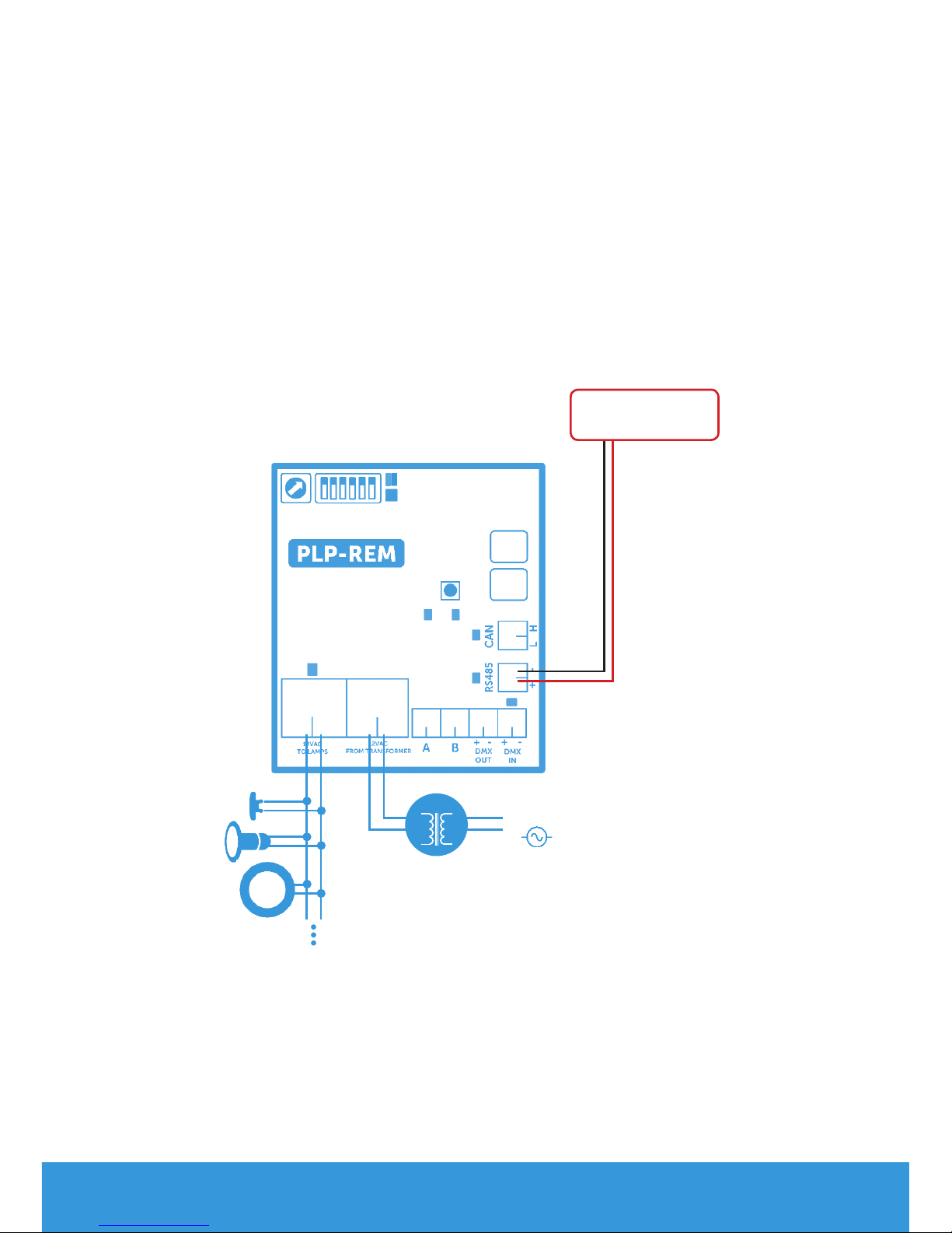
DMX 512 communication
Single PLP-REM unit
1) Make sure DIP switch 1 is switched OFF.
2) Make sure the lights are turned ON with the remote first.
Address dial setup
Setting the DMX address of the PLP-REM:
Select the desired number on the address dial. The chosen number deter-
mines the DMX addresses of the PLP-REM & lamps.
Each lamp uses 3 bytes of DMX data (R-G-B), and all lamps receive the same
DMX data from the PLP-REM.
The DMX start address can be overruled by using the RS-485 command:
“set DMX start address” (see page 15)
DMX
address 1 2 3 4 5 6 7 8 9 ...
0 1 2 ...
R G B R G B R G B ...
Address dial
position
230VAC
Address dial
Connect DMX
panel
to DMX IN (+/-)
DMX PANEL
12VAC

13
ENG
Multiple PLP-REM installation
1) Connect the DMX panel to the “DMX IN” port of the first PLP-REM
2) Connect the PLP-REM’s with each other (open loop):
DMX OUT --> DMX IN (polarized terminals + -)
3) Set the DMX address for each PLP-REM via the address dial.
- Option 1:All PLP-REM’s can be set to the same address:
This implies that all lamps will receive the same DMX data,
And will all operate identically
- Option 2:PLP-REM’s can be set to dierent addresses:
Each PLP-REM will have it’s own group of connected lamps
that will operate identically.
However, since each PLP-REM has it’s own unique address,
the dierent lamp groups can be controlled separately
DMX PANEL
Address dial Address dial
Address dial
230VAC
12VAC
230VAC
12VAC
230VAC
12VAC
14
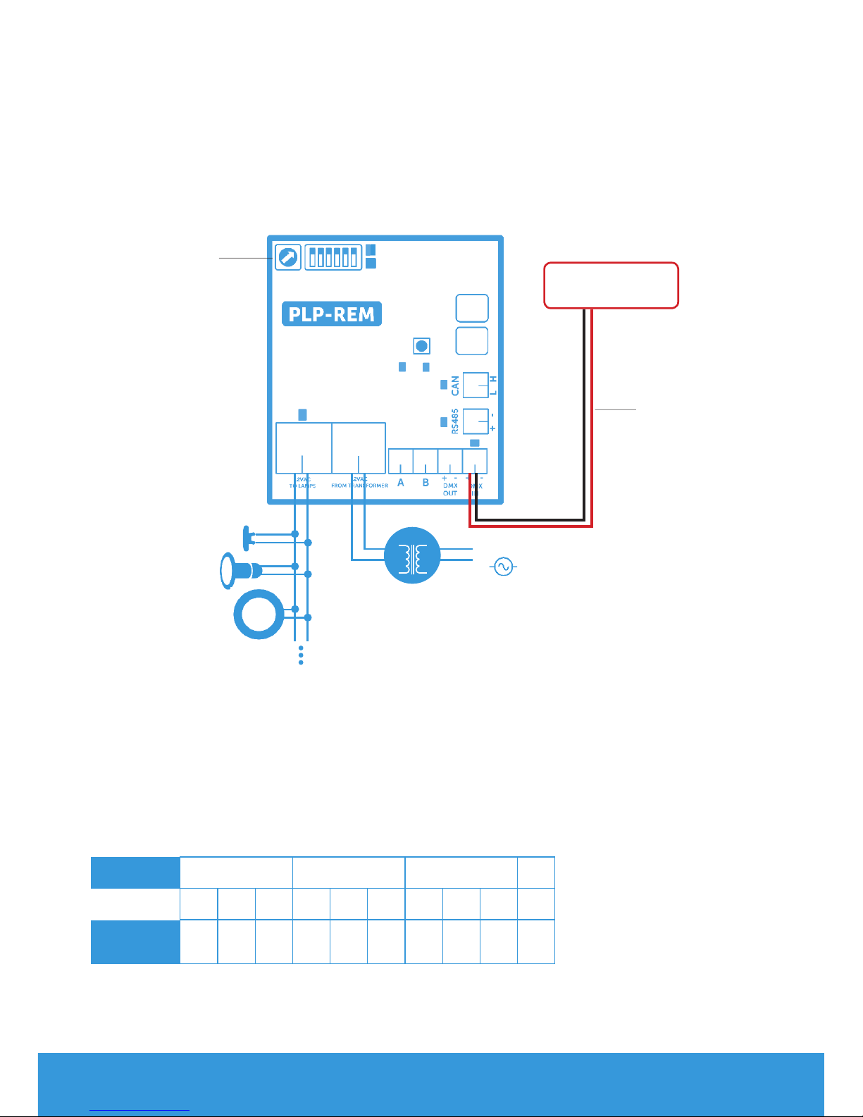
RS-485 communication
1) Make sure DIP switch 1 is switched OFF.
2) Make sure the lights are turned ON with the remote first.
3)Connect the RS-485 source to the “485” port on the PLP-REM
4)Communication settings: 9600, 8, 1, n
5) Command list: see page 15
Single PLP-REM unit
RS485 Source
230VAC
12VAC

15
ENG
RS-485 Command set
Command Command Remark Example available in
ON/OFF mode
available in
PLC mode
Lamps OFF PL0 All lamps OFF X X
Lamps ON PL1 All lamps ON X X
Program UP PsU Jump to next program X X
Program Down PsD Return to previous program X
Set Program PSxx xx is the decimal representaon
of the program number (01 - 14) PS06 = jump to program 6 X
Auto sync procedure PsS executes the auto sync procedure (see page 10) X X
White 1 PW1 Jump to White 1 (program 12) X
White 2 PW2 Jump to White 2 (program 13) X
White 3 PW3 Jump to White 3 (program 14) X
Set RGB PCrrrgggbbb rrr, ggg and bbb are the decimal representaon
of the RGB value (with leading zero’s)
1) PC255128064 = Full output level on Red color, half out-
put level on Green color, 1/4 output level on Blue color
2) PC255255255 = All colors at full output level
3) PC000000000 = All colors OFF
X
Set Dim value PDxxx set the OUTPUT value of the lamp in % (000 -
100) PD075 = 75% output level (on all LED’s) X
set DMX startAdress PAxxxyz y = ‘e’ or ‘E’ PA035E = set DMX start address to 35 [35(R), 36(G),
37(B)] X
Set color in percentage Pprgbe variable size, rgb = ASCII 0-255, e = end character Pp25050100e = Red 25%, Green 50%, Blue 100% X
Set color in hex Pcrgbe variable size, rgb = ASCII 0-255, e = end character Pc64128255e = Red 25%, Green 50%, Blue 100% X
Relay A control PRAx x = 1 (ON), 0 (OFF), P (Pulse) !this overrules
dipswitch PRA1 = Relay A ON PRA0 = Relay A OFF X X
Relay B control PRBx x = 1 (ON), 0 (OFF), P (Pulse) !this overrules
dipswitch PRB1 = Relay B ON PRB0 = Relay B OFF X X
ON/OFF relay control PRMx x = 1 (ON), 0 (OFF) PRM1 = Relay ON/OFF control ON X X
Color temperature PTxyz x = ten thousand ; y = thousand ; z = hundred PT035 = Set white color temperature to 3500K (in steps
of 500K) X

16
RESET procedure
RESET procedure for the control board
1) Make sure the PLP-REM is powered ON
2) Press and hold the RESET button on the logic board
3) The blue LED will light up
4) Release the RESET button when the blue LED turns o
The control board has been RESET.
And all transmitters have been unpaired.
RESET
button
Blue
LED
DuraLink
!

17
ENG
Troubleshooting
PROBLEM SOLUTION
The PLP-REM doesn’t react to
transmitter commands
• Perform a RESET procedure
• Check the battery of the handheld
transmitter (see below)
• The transmitter is not paired-
correctly with the PLP-REM.
Repeat the pairing process
• Reduce the distance between
handheld transmitter and PLP-REM
and/or remove obstacles
• Check the General status light on
the logic board. If it’s red, then
the secondary voltage is too high
(>14VAC) or there is a short circuit
The pool lights don’t work
or don’t change colors
correclty
• Perform a RESET procedure
• Check if all connections are made
according to the electrical scheme.
• Switch the PLP-REM to ON/OFF
mode (DIP switch nr 1) and check if
the lamps work
Transmitter battery
+
-
• Remove the philips head screw and open the transmitter
• Replace the battery, respecting the polarity
Battery type: A23 12V
Check battery status:
Replacing transmitter battery:
Push and release any button on the remote. The green LED should still
light up 0,5 second after you released. If the LED stops faster, then the
battery needs to be replaced

18
Pool light wiring instructions
Each lamp is connected to the transformer by a separate cable
(Preferred for new installations)
Separate cable ( not included )
Pool
house
Pool
4m cable included in lamp package !Always use a toroïdal transformer
SELECT
CABLE SECTION & MAXIMUM LENGTH

19
ENG
* The transformer VA rating must be greater or equal to the sum of VA ratings of
all connected lamps.
These cable lenghts are calculated with worst case voltage drops in the
electrical wiring.
MAXIMUM AND STABLE LIGHT OUTPUT IS ONLY GUARANTEED WHEN
THE INSTALLED CABLE CROSS SECTION MATCHES OR EXCEEDS THE
ADVISED VALUES IN THE ABOVE TABLE
SELECT
CABLE SECTION & MAXIMUM LENGTH
LAMP TYPE 1,5mm22,5mm24,0mm26,0mm210mm2VA TRANSFORMER
(12VAC)*
PLP050-WH
PLP050-WW
PLP050-BL
122m 204m 326m 490m 820m 8 VA
PLP050-RGB 79m 132m 212m 318m 530m 12 VA
PLP100-WH
PLP100-WW
PLP100-BL
26m 43m 69m 104m 173m 32 VA
PLP100-RGB 15m 25m 41m 61m 100m 48 VA
PLP170-WH
PLP170-WW
PLP170-BL
11m 19m 30m 46m 75m 66 VA
PLP170-RGB 8m 14m 23m 35m 57m 80 VA

20
Wiring remark
Third party equipment such as frequency inverters and electric motors can
generate excessive noise on the 230VAC / 400VAC power line.
This noise might be injected into the adjacent 12VAC power line and dis-
turb the power line communication towards the AdagioPro RGB lights.
To prevent this, please take care of the following:
!Keep 230VAC / 400VAC power line cables at least 50cm separated
over their full length from the 12VAC power line towards any RGB
lights
Do not mix 12VAC and 230VAC / 400VAC power line cables into the
same cable trays
!
Pool
house
Pool
12VAC to lamps
230VAC / 400VAC to third party equipment
230VAC Min. 50cm
(**)
(**) Do not mix 12VAC and 230VAC / 400VAC power line cables into the
same cable trays
Table of contents
Languages:
Other Spectravision Remote Control manuals


Popular Remote Control manuals by other brands

Reely
Reely HT-6 manual

FUTABA
FUTABA T6L SPORT instruction manual

LG
LG PQRCUDS0 Owners & installation manual

Universal Remote Control
Universal Remote Control Easy Clicker UR3-SR3 operating manual

Amino
Amino Nova Guide

Hunter
Hunter Universal Fan and Light Remote Control Owner's guide and installation manual


