Spectris Servomex OxyDetect User manual
Part Number: 05311001B
Revision: 4
Language: UK English
SERVOMEX OxyDetect
OPERATOR MANUAL

OxyDetect Oxygen Deficiency Gas Detector Contents
05311001B / Revision 4 i
IMPORTANT INFORMATION
Continued safe and reliable operation of this equipment is
conditional on all installation, operation and maintenance
procedures being carried out in accordance with the appropriate
manuals, by personnel having
appropriate qualifications,
experience and training.
Poursuite de l'exploitation sûre et fiable de cet équipement est
subordonné à toutes les procédures d'installation, de
fonctionnement et d'entretien étant effectué en conformité avec les
manuels appropri
és, par un personnel ayant les qualifications
appropriées, l'expérience et la formation.
Failure to observe the requirements of the manual may result in the user being held
responsible for the consequences and may invalidate any warranty.
Servomex will accept no liability for unauthorised modifications to Servomex supplied
equipment.
Servomex has paid particular attention to Health & Safety throughout the manual. Where
special precautions need to be taken due to the nature of the equipment or product, an
appropriate safety icon and warning message is shown. Special attention should be made
to Section 1.2, where all such messages are summarized.
In line with our continuous policy of research and development, we reserve the right to
amend models and specifications without prior notice.
This manual is accurate at the date of printing, but will be superseded and should be
disregarded if specifications or appearance are changed.
Servomexis a registeredtrademarkof Servomex Group Limited. The use ofall trademarks
in this document is acknowledged.
© 2016. Servomex Group Limited. A Spectris Company. All rights reserved.

Contents OxyDetect Oxygen Deficiency Gas Detector
ii 05311001B / Revision 4
CONTENTS
Section
Page
1DESCRIPTION AND DEFINITIONS ............................................................1
1.1 Scope of this manual...................................................................................1
1.2 Safety information .......................................................................................1
1.3 Description..................................................................................................2
1.4 Ordering options..........................................................................................3
1.5 Certification.................................................................................................5
1.5.1 Hazardous area certification...................................................................5
1.6 Markings.....................................................................................................7
1.6.1 Label locations.......................................................................................8
2CERTIFICATION INFORMATION................................................................9
2.1 Hazardous area approval and certification...................................................9
2.1.1 Equipment certification standards...........................................................9
2.1.2 Europe and IECEx..................................................................................9
2.1.3 North America......................................................................................10
2.1.4 Label information..................................................................................10
3SPECIFICATION.......................................................................................12
3.1 General.....................................................................................................12
3.2 Environmental limits ..................................................................................12
4UNPACK THE INSTRUMENT ...................................................................14
5INSTRUMENT USER INTERFACE ...........................................................15
5.1 Introduction...............................................................................................15
5.2 Start-up and measurement screens...........................................................15
5.3 Soft key legends........................................................................................16
5.4 System and measurement status icons......................................................17
5.5 Scroll bars.................................................................................................17
5.6 Menu options/screens and password protection.........................................17
5.7 The menu screen ......................................................................................18
5.8 The settings screen...................................................................................19
5.9 The information screen..............................................................................20
5.10 Editing on-screen data...............................................................................20
6INSTALLATION AND SET-UP...................................................................22
6.1 Mechanical installation...............................................................................23
6.2 Electrical Installation..................................................................................23
6.2.1 Electrical Safety....................................................................................23
6.2.2 Electrical data.......................................................................................26
6.2.3 Connect the electrical supply................................................................28
6.2.4 Analogue output connections................................................................30
6.2.5 Interface Relay connections..................................................................32
6.2.6 Modbus Ethernet connection (option)....................................................33
6.3 Switch on/set-up........................................................................................34
6.3.1 Selecting the security level and password(s).........................................34
6.3.2 Selecting the security level ...................................................................35

OxyDetect Oxygen Deficiency Gas Detector Contents
05311001B / Revision 4 iii
6.3.3 Changing passwords............................................................................36
6.3.4 Adjusting the screen contrast................................................................36
6.3.5 Adjusting the backlight timer.................................................................37
6.3.6 Setting the clock...................................................................................38
6.3.7 Changing regional settings ...................................................................38
6.4 Configuring and using the mA outputs (option)...........................................39
6.4.1 Overview..............................................................................................39
6.4.2 Introduction to the mA output parameters .............................................39
6.4.3 Setting up the mA output parameters....................................................41
6.4.4 Calibrating the mA output.....................................................................43
6.5 Configuring the measurement alarms........................................................44
6.5.1 Alarm modes and levels .......................................................................44
6.5.2 Latching/non-latching alarms................................................................46
6.5.3 Hysteresis levels ..................................................................................46
6.5.4 Viewing the measurement alarm status.................................................47
7CALIBRATION..........................................................................................48
7.1 Connecting the calibration gas cap............................................................50
7.2 Manual calibration.....................................................................................51
8ROUTINE MAINTENANCE........................................................................53
8.1 Inspecting the calibration cap ....................................................................53
8.2 Checking the mA output ............................................................................53
8.3 Checking the relays...................................................................................53
8.4 Cleaning the instrument.............................................................................54
8.5 Preventative maintenance.........................................................................54
9FAULT FINDING.......................................................................................56
9.1 Fault, maintenance required and SIP statuses...........................................56
9.1.1 Status definitions..................................................................................56
9.1.2 Status annunciations............................................................................56
9.2 Viewing messages.....................................................................................58
9.2.1 Active messages ..................................................................................58
9.2.2 View history messages.........................................................................59
9.3 General fault finding..................................................................................59
10 STORAGE AND DISPOSAL......................................................................62
10.1 Storage.....................................................................................................62
10.2 Disposal....................................................................................................62
11 SPARES...................................................................................................63
12 DISPOSAL IN ACCORDANCE WITH THE WASTE ELECTRICAL AND
ELECTRONIC EQUIPMENT (WEEE) DIRECTIVE ....................................64
13 APPENDIX................................................................................................65
A1 PERFORMANCE DATA............................................................................65
A2 FACTORY CONFIGURATION SETTINGS ................................................66
A3 IMPLEMENTATION GUIDE FOR MODBUS ETHERNET
COMMUNICATIONS (OPTION) ................................................................67

Contents OxyDetect Oxygen Deficiency Gas Detector
iv 05311001B / Revision 4
A3.1 Introduction...............................................................................................67
A3.2 References................................................................................................67
A3.3 Supported function codes..........................................................................67
A3.4 Exception codes........................................................................................67
A3.5 Addressing................................................................................................68
A3.6 Floating point numbers..............................................................................68
A3.7 System data mapping................................................................................68
A3.8 Transducer data mapping..........................................................................68
A3.9 System Fault Mapping...............................................................................70
A3.10 Transducer fault and alarm mapping..........................................................71
A3.11 System set-up mapping.............................................................................73
A3.12 Transducer set-up mapping.......................................................................74
A3.13 System control ..........................................................................................75
A3.14 Transducer control.....................................................................................75
A4 CONFIGURING THE MODBUS PARAMETERS (OPTION).......................77
A4.1 TCP (Ethernet) Communications parameters.............................................77
A5 CROSS INTERFERENCE OFFSETS........................................................79
A6 END USER NOTES...................................................................................83
© This manual is copyright, and no part of it may be reproduced without Servomex's written approval.

OxyDetect Oxygen Deficiency Gas Detector 1 – Description and definitions
05311001B / Revision 4 1
1 DESCRIPTION AND DEFINITIONS
1.1 Scope of this manual
This manual provides installation, operation and routine maintenance instructions for
the 05311B1 OxyDetect - Oxygen Deficiency Fixed Gas Detector, abbreviated to
"instrument" or “unit” in the remainder of this manual.
1.2 Safety information
Read this manual and ensure that you fully understand its content before you attempt
to install, use or maintain the instrument. Important safety information is highlighted in
this manual as WARNINGs and CAUTIONs, which are used as follows:
Warnings highlight specific hazards which, if not taken into
account, may result in personal injury or death.
Avertissements soulignent les dangers spécifiques qui, si pas
pris en compte, peut entraîner des blessures ou la mort.
Cautions highlight hazards which, if not taken into account, can
result in damage to the instrument or to other equipment or
property.
Précautions soulignent les dangers qui, si pas pris en compte,
peut entraîner des dommages à l'instrument ou à un autre
appareil ou d'un bien.
This manual also incorporates 'Be aware of' information, which is used as follows:
This highlights information which it is useful for
you to be aware of (for
example, specific operating conditions, and so on).

1 – Description and definitions OxyDetect Oxygen Deficiency Gas Detector
2 05311001B / Revision 4
1.3 Description
The Instrument is a fixed wall mounted gas detector with an integral oxygen sensor
that outputs a linear 4-20mA signal that represents an ambient oxygen concentration.
Additionally, three changeover relays are provided to signal the following detector
statuses.
Measurement alarm level 1 (user configurable)
Measurement alarm level 2 (user configurable)
Instrument Fault and Oxygen measurement >23%
These outputs must be integrated into a gas detection management system as the
instrument gives no direct visible or audible warning or alarm of an oxygen-deficient
environment (internal audible alarm or visual beacon), its function being solely to
measure the ambient level of oxygen. It offers a measurement of ambient oxygen
based on the principles of paramagnetism, a non-depleting and inherently linear
measurement technique.
The instrument is designed to be installed within indoor working environments such
as laboratories, workshops or analyser shelters.
Gas sample measurements are shown on the instrument display, and can be output
as a 4-20mA milliamp (mA) signal and / or gas sample alarm levels indicted by relay
status, to a gas detection management system.
The instrument requires little routine maintenance, other than calibration which is
essential for the accuracy of the gas measurements.
The instrument is not to be used for process control or process
monitoring
L'instrument ne doit pas être utilisé pour le contrôle des
processus ou la surveillance de processus
The OxyDetect is not a medical device as defined in the medical
devices directive 93/42/EEC and is not intended to be used on
human beings for the diagnosis, prevention, monitoring,
treatment or alleviation of disease. Injury or replacement or
modification of the anatomy
Le OxyDetect est pas un dispositif médical tel que défini dans
les dispositifs médicaux de la directive 93/42 / CEE et ne sont
pas destinés à être utilisés sur des êtres humains pour le
diagnostic, la prévention, contrôle, traitement ou atténuation
d'une maladie. Blessure ou de remplacement ou modification de
l'anatomie.
OxyDetect Oxygen Deficiency Gas Detector 1 – Description and definitions
05311001B / Revision 4 3
The safe area version is not to be used in certified or hazardous
locations (potentially explosive atmospheres)
La version de zone de sécurité ne doit pas être utilisé dans des
endroits certifiés ou dangereux (atmosphères explosibles)
The instrument is not suitable for corrosive atmospheres (those
atmospheres where gases and vapours are present in
concentrations high enough to cause corrosion to normal
industrial appliances or where specialised coatings, materials or
finishes would normally be specified to avoid corrosion)
L'instrument ne convient pas pour les atmosphères corrosives
(ces atmosphères gaz et les vapeurs sont présents dans des
concentrations suffisamment élevées pour provoquer la
corrosion des appareils industriels ou normales où devraient
normalement être précisées revêtements spécialisés, des
matériaux ou finitions pour éviter la corrosion)
1.4 Ordering options
For the latest ordering options please contact your local Servomex agent or visit
www.servomex.com.
1 – Description and definitions OxyDetect Oxygen Deficiency Gas Detector
4 05311001B / Revision 4
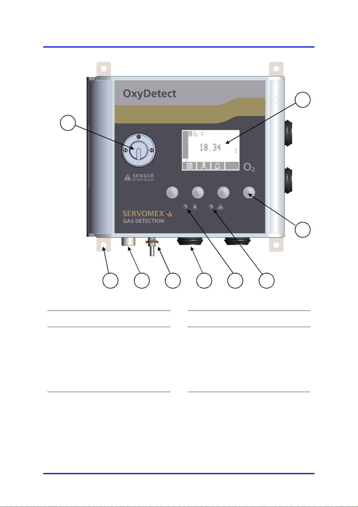
Key Description Key Description
1. 4 x mounting holes for M6 fixings
2. Display
3. 4 x Gland entries holes diameter
22mm
4. Fault LED (amber)
5. Measurement alarm LED (red)
6. Chassis earth
7. Enclosure breather (do not block)
8. Soft key 4, from left to right soft
keys 1, 2, 3 and 4
9. Senor cover and calibration cap
mounting nozzle
Figure 1 - Front of Instrument
1
2
3
4
5
6
7
8
9

OxyDetect Oxygen Deficiency Gas Detector 1 – Description and definitions
05311001B / Revision 4 5
1.5 Certification
1.5.1 Hazardous area certification
Do not modify the unit, either mechanically or electrically, as the
certification of the instrument will be invalidated and it may not
operate safely.
Ne modifiez pas l'unité, soit mécaniquement ou électriquement,
ou la certification de l'instrument sera invalidée et il ne peut pas
fonctionner en toute sécurité.
Hazardous area certification is restricted to the use of the unit in
atmospheres at normal oxygen concentration and normal
atmospheric pressures. The oxygen measurement range for
hazardous area versions is 0 to 21%.
Certification de zone dangereuse est limitée à l'utilisation de
l'appareil dans des atmosphères à la concentration d'oxygène
normale et des pressions atmosphériques normales . plage de
mesure de l'oxygène pour les versions en zone dangereuse est
0 à 21 %.
Exposure to some
chemicals may degrade the sealing
properties of materials used in the following devices.
K1: Relay from Customer Interface Board - Sealed Device
K2: Relay from Customer Interface Board - Sealed Device
K3: Relay from Customer Interface Board - Sealed Device
L’exposition à certains produits chimiques mai dégrader la
fermeture des propriétés des matériaux utilisés dans les appareils
suivants: (Amérique du Nord uniquement).
K1: Relais de Carte Interface HM - Sealed Device
K2: Relais de Carte Interface HM - Sealed Device
K3: Relais de Carte Interface HM - Sealed Device
Substitution of the following components may impair suitability
for Division 2 (North America only).
K1: Relay from Customer Interface Board - Sealed Device
K2: Relay from Customer Interface Board - Sealed Device
K3: Relay from Customer Interface Board - Sealed Device
La substitution de composants suivants peut render ce matériel
inacceptable pour les emplacements de Classe 1, Division 2:
(Amérique du Nord uniquement).
1 – Description and definitions OxyDetect Oxygen Deficiency Gas Detector
6 05311001B / Revision 4
K1: Relais de Carte Interface HM - Sealed Device
K2: Relais de Carte Interface HM - Sealed Device
K3: Relais de Carte Interface HM - Sealed Device
EXPLOSION HAZARD - Substitution of components may impair
suitability for CL I, Div 2. (North America only)
RISQUE D’EXPLOSION – La substitution de composants peut
render ce matériel inacceptable pour les emplacements de
Classe I, Division 2. (Amérique du Nord uniquement)
Make sure that the operating environment is within the limits
specified in the product data (section 3.2).
Assurez-vous que l'environnement d'exploitation est dans les
limites spécifiées dans les données du produit (section 3.2).
Do not open the enclosure if an explosive atmosphere is present.
Ne pas ouvrir en atmosphère explosive.
Do not open the enclosure if the instrument is energized.
Ne pas ouvrir sous tension.
It is a condition of certification that the unit must be installed
following the appropriate national or international legislation or
codes of practice. In particular, you must make sure that the
correct glands are fitted to cable entries and that you do not
compromise the weatherproofing of the enclosure.
C'est une condition de la certification que l'unité doit être
installée en respectant la législation ou des codes de pratique
nationale ou internationale approprié. En particulier, vous devez
vous assurer que les glandes appropriés sont installés aux
entrées de câble et que vous ne compromettent pas l'étanchéité
de l'enceinte.
All of the monitor electrical connections are considered to be
incendive and therefore must only be connected to safe area
equipment.
Tous les moniteurs connexions électriques sont considérés
comme incendiaire et donc ne doit être connecté à l'équipement
des zones de sécurité.
OxyDetect Oxygen Deficiency Gas Detector 1 – Description and definitions
05311001B / Revision 4 7
Only use a soft, clean cloth moistened with water to wipe clean
the outside of the enclosure.
Utilisez uniquement un chiffon doux et propre humidifié avec de
l'eau pour nettoyer l'extérieur de l'enceinte.
The equipment is incapable of passing the dielectric strength
test prescribed by the standards, and so this must be taken into
account during installation.
L'équipement est incapable de passer le test de rigidité
diélectrique prescrite par les normes, et si cela doit être pris en
compte lors de l'installation.
The equipment shall be used in an area not exceeding Pollution
Degree 2 as defined in IEC 60664-1.
L'équipement doit être utilisé dans une zone ne dépassant pas
2 degré de pollution tel que défini dans la norme CEI 60664-1.
1.6 Markings
The instrument includes these external markings. Their details are shown in Section Error!
Reference source not found..
Follow the appropriate safety instructions and be aware of any warnings about potential
hazards.
1 – Description and definitions OxyDetect Oxygen Deficiency Gas Detector
8 05311001B / Revision 4
1.6.1 Label locations
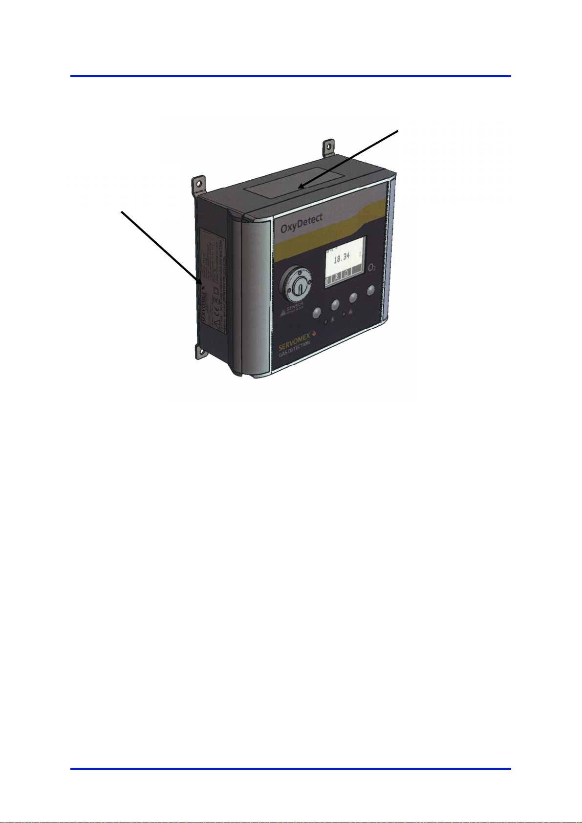
Figure 2 - OxyDetect unit label locations
OxyDetect unit
Certification label
(fitted on hazardous
location versions
only. See Figure 4 &
Figure 5)
OxyDetect unit rating
& serial number label
(Figure 3)

OxyDetect Oxygen Deficiency Gas Detector 2 – Certification information
05311001B / Revision 4 9
2 CERTIFICATION INFORMATION
2.1 Hazardous area approval and certification
2.1.1 Equipment certification standards
The standards to which the equipment has been certified are listed below:
ATEX
EN 60079-0:2012 + A11 :2013
EN 60079-7 :2015
EN 60079-11:2012
EN 60079-15:2010
IECEx
IEC 60079-0:2011 Edition 6
IEC 60079-7 :2015 Edition 5
IEC 60079-11:2011 Edition 6
IEC 60079-15:2010 Edition 4
2.1.2 Europe and IECEx
ATEX II 3G
Coding (ATEX and IECEx) Ex ic ec nC IIC T4 Gc
Ambient Temperature
range -5 °C to +45 °C
Certification number
(ATEX) Baseefa15ATEX0165X
Certification number
(IECEx) IECEx BAS 15.0112X
Conditions of safe use
(ATEX & IECEx)
1. Possible electrostatic risk - clean only with a
damp cloth.
2. The equipment is not capable of passing
the dielectric strength test prescribed by the
standards, and so this must be taken into
account during installation.
3. The equipment shall be used in an area not
exceeding pollution degree 2 as defined in
IEC 60664-1.
4. All cable entries must utilise a suitably
certified cable gland or, in the case of any
unused entries, a suitably certified blanking
element in order to maintain the pollution
degree level and ingress protection IP66 of
the equipment.

2 – Certification information OxyDetect Oxygen Deficiency Gas Detector
10 05311001B / Revision 4
2.1.3 North America
Coding Class I, Division 2, Groups A-D; T4
Class I, Zone 2, Group IIC; T4
Ambient Temperature
range -5 °C to +45 °C
SGS Contract No. 710216
SGS Certificate Reference SGSNA/19/SUW/00043
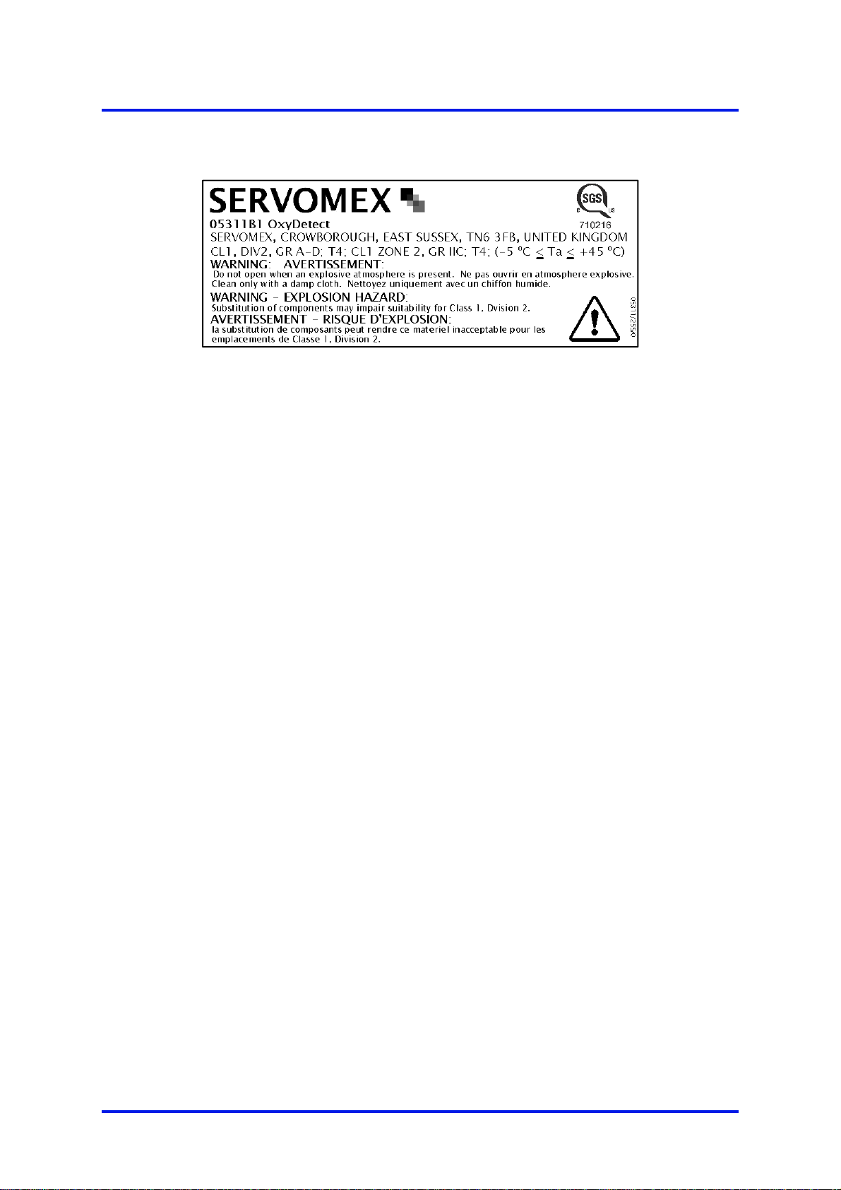
2.1.4 Label information
Figure 3 - OxyDetect Rating Label
Figure 4 - OxyDetect ATEX / IECEx Certification label
OxyDetect Oxygen Deficiency Gas Detector 2 – Certification information
05311001B / Revision 4 11
Figure 5 - OxyDetect North America
CL1 Div 2 Certification label
3 – Specification OxyDetect Oxygen Deficiency Gas Detector
12 05311001B / Revision 4
3 SPECIFICATION
The protection, accuracy, operation and condition of the
equipment may be impaired if the instrument is not installed in
accordance with the requirements of this and subsequent
sections of the manual.
La protection, la précision, le fonctionnement et l'état de
l'équipement peut être altérée si l'instrument n'a pas été installé
en conformité avec les exigences du présent et les sections
suivantes du manuel.
3.1 General
Dimensions:
length x height x width 210 x 200 x 106 mm (8.3” x 7.9” x 4.2”)
Mass <2.5 kg (5.5lbs)
3.2 Environmental limits
Equipment is suitable for indoor use only
Ambient temperature range
Operational
Hazardous location certified
+5 °C to +45 °C (+41 °F to +113 °F)
-5 °C to +45 °C (+23 °F to +113 °F)
Storage -5 °C to +50 °C (+23 °F to +122 °F)
Operating pressure range Ambient
80 to 110 kPa (11.6 to 16 psi) Hazardous
Areas
Operating ambient humidity range 10 to 80% RH, non-condensing
Operating altitude range –500 * to 2000
†
metres
(-1600 * to 6500 †feet)
Ingress protection IP66 (IP40 sensor)
The instrument is rated Pollution Degree 2
* Below sea level.
†Above sea level.

05311001B / Revision 4 13
The OxyDetect enclosure is designed such that it achieves
IP66 ingress protection. However, in operational use
consideration must be made for the protection of the sensor
opening which is rated to IP40. Therefore, the instrument should
not be exposed to washing with liquid jets. The instrument is for
indoor use only.
L'enceinte OxyDetect estconçue de telle sorte qu'elle réalise
IP66 protection d'entrée. Cependant, dans l'utilisation
opérationnelle examen doit être fait pour la protection de
l'ouverture du capteur qui est évalué à IP40. Par conséquent,
l'instrument ne doit pas être exposé à un lavage avec jets de
liquide. L'instrument est destiné à être utilisé en intérieur.
If the ambient temperature falls below 0 °C (32 °F) the instrument
should be recalibrated to ensure correct operation.
Si la température ambiante descend en dessous de 0 °C (32 °F)
l'instrument doit être recalibré pour assurer un fonctionnement
correct.

4 – Unpack the instrument OxyDetect Oxygen Deficiency Gas Detector
14 05311001B / Revision 4
4 UNPACK THE INSTRUMENT
The instrument is delicate and care must be taken when
handling.
L'instrument est délicate et il faut prendre soin lors de la
manipulation.
1. Remove the instrument and any other equipment from its packaging.
It is advisable that the gland entry blanking plugs are only removed
just prior
to product installation.
2. Inspect the instrument and the other items supplied, and check that they are not
damaged. If any item is damaged, immediately contact Servomex or your local
Servomex agent.
3. Check that you have received all of the items that you ordered. If any item is
missing, immediately contact Servomex or your local Servomex agent.
4. If you do not intend to use the instrument immediately:
Refit any protective plastic covers.
Place the instrument and any other equipment supplied back in its protective
packaging.
Store the instrument as described in Section 10.1.
Otherwise, read Section 5 (Instrument user interface), and then continue at
Section 6 onwards to install, set up, and use the instrument.
Retain the shipping documentation and packaging for future use (for example,
return of the instrument to Servomex for servicing or repair).
05311001B / Revision 4 15
5 INSTRUMENT USER INTERFACE
5.1 Introduction
The instrument user interface comprises the following (shown on Figure 1):
Display Shows various screens: see Section 5.2 onwards
Soft keys The function of each of the soft keys depends on the screen
currently being shown on the display: see Section 5.2
Alarm LED On when an alarm condition exists: see Section 6.5
Fault LED On when a fault condition exists: see Section 9.1
5.2 Start-up and measurement screens
When you first switch on the instrument, a 'start-up screen' is displayed while the
instrument carries out a self-test.
The start-up screen shows the Servomex name, a 'self-test time elapsed/remaining'
indicator, and messages identifying the tasks being carried out as part of the self-test.
The screen will initially display the "System Check" task message. The measurement
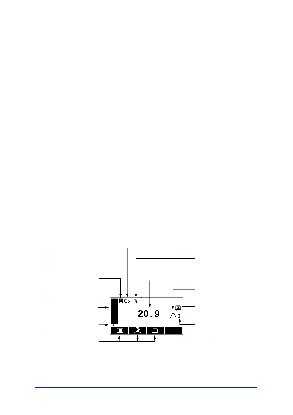
screen is then displayed, as shown in Figure 6 below.
Figure 6 - The measurement screen
Gas being measured
Measurement units
Pressure compensation
indicator *
Current measurement
Alarm icon
(see Section 6.5.1)
mA Range
(see Section 6.4.1)
Icons
(see Section 9.1.2)
Soft key legends
Status icon bar
(see Section 5.4)
Transducer number
("1" always shown)
Software health indicator
This manual suits for next models
1
Table of contents
Popular Gas Detector manuals by other brands

ELRO
ELRO ES46 quick start guide

BEINAT
BEINAT CO922 Guide

Critical Environment Technologies
Critical Environment Technologies LPT-M Operation manual
Beacon
Beacon MEGA Installation, operation and maintenance instructions

Bosean Electronic Technology
Bosean Electronic Technology BH-4M user manual

Duomo
Duomo CellAir user manual


Heath Consultants
Heath Consultants RMLD-CS HPN 105301 Operator's manual

RKI Instruments
RKI Instruments 65-2495RK Operator's manual

Riken Keiki
Riken Keiki SD-1DOX operating manual

MSA AUER
MSA AUER ALTAIR operating manual

Riken Keiki
Riken Keiki GD-84D-EX Series operating manual

CALECTRO
CALECTRO SenseAir A-SENSE Manual for installation