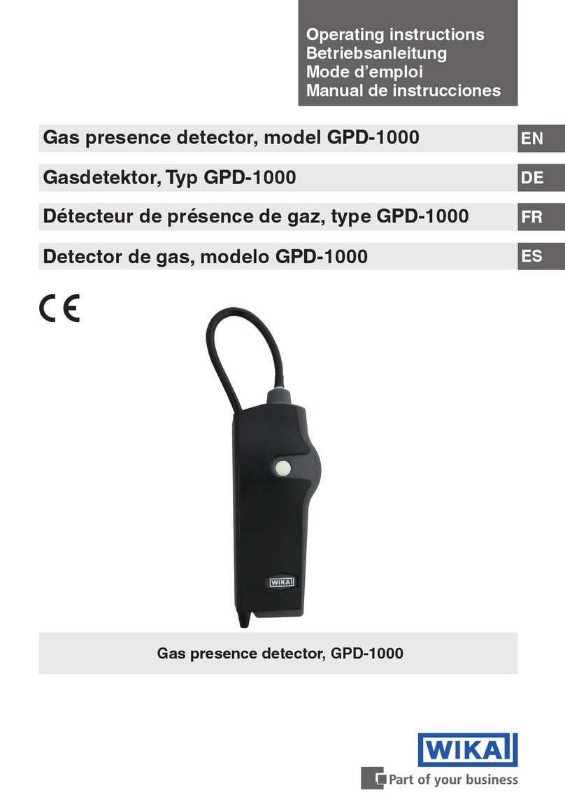
WIKA GIR-10 User manual

Operating instructions
Betriebsanleitung
Mode d’emploi
Manual de instrucciones
EN
DE
FR
ES
Gas detector, model GIR-10
Gasdetektor, Typ GIR-10
Gas detector, GIR-10
Détecteur de gaz, type GIR-10
Detector de gas, modelo GIR-10

2
14008231.01 04/2020 EN/DE/FR/ES
WIKA operating instructions gas detector, model GIR-10
EN
DE
FR
ES
Operating instructions model GIR-10 Page 3 - 28
Betriebsanleitung Typ GIR-10 Seite 29 - 54
© 03/2011 WIKA Alexander Wiegand SE & Co. KG
All rights reserved. / Alle Rechte vorbehalten.
WIKA®is a registered trademark in various countries.
WIKA®ist eine geschützte Marke in verschiedenen Ländern.
Prior to starting any work, read the operating instructions!
Keep for later use!
Vor Beginn aller Arbeiten Betriebsanleitung lesen!
Zum späteren Gebrauch aufbewahren!
Lire le mode d‘emploi avant de commencer toute opération !
A conserver pour une utilisation ultérieure !
¡Leer el manual de instrucciones antes de comenzar cualquier trabajo!
¡Guardar el manual para una eventual consulta!
Mode d'emploi type GIR-10 Page 55 - 80
Manual de instrucciones modelo GIR-10 Página 81 - 106

3WIKA operating instructions gas detector, model GIR-10
14008231.01 04/2020 EN/DE/FR/ES
EN
Contents
Contents
1. General information 4
2. Design and function 5
2.1 Overview . . . . . . . . . . . . . . . . . . . . . . . . . . . 5
2.2 Description . . . . . . . . . . . . . . . . . . . . . . . . . . 6
2.3 Scope of delivery . . . . . . . . . . . . . . . . . . . . . . . . 6
3. Safety 7
3.1 Explanation of symbols . . . . . . . . . . . . . . . . . . . . . . 7
3.2 Intended use . . . . . . . . . . . . . . . . . . . . . . . . . . 7
3.3 Improper use. . . . . . . . . . . . . . . . . . . . . . . . . . 8
3.4 Responsibility of the operator . . . . . . . . . . . . . . . . . . . . 8
3.5 Personnel qualification . . . . . . . . . . . . . . . . . . . . . . 9
3.6 Personal protective equipment. . . . . . . . . . . . . . . . . . . . 9
3.7 Handling of insulating gases and gas mixtures . . . . . . . . . . . . . 10
3.8 Valid standards and directives . . . . . . . . . . . . . . . . . . . 11
3.9 Labelling, safety marks . . . . . . . . . . . . . . . . . . . . . 12
4. Transport, packaging and storage 13
4.1 Transport . . . . . . . . . . . . . . . . . . . . . . . . . . 13
4.2 Packaging and storage . . . . . . . . . . . . . . . . . . . . . 13
5. Commissioning, operation 14
5.1 Overview of the controls . . . . . . . . . . . . . . . . . . . . . 14
5.2 Switching on and off . . . . . . . . . . . . . . . . . . . . . . 15
5.3 Charging the battery . . . . . . . . . . . . . . . . . . . . . . 15
5.4 Performing measurements . . . . . . . . . . . . . . . . . . . . 16
5.5 Settings . . . . . . . . . . . . . . . . . . . . . . . . . . 18
5.5.1 Zero point setting . . . . . . . . . . . . . . . . . . . . . . 18
5.5.2 Resetting . . . . . . . . . . . . . . . . . . . . . . . . . 19
5.5.3 Changing displayed units (only for SF₆ gas versions) . . . . . . . . . . 19
5.5.4 Cleaning or replacing the particle filter . . . . . . . . . . . . . . . 20
6. Faults 20
7. Maintenance, cleaning and recalibration 21
7.1 Maintenance . . . . . . . . . . . . . . . . . . . . . . . . . 21
7.2 Cleaning . . . . . . . . . . . . . . . . . . . . . . . . . . 21
7.3 Recalibration. . . . . . . . . . . . . . . . . . . . . . . . . 21
8. Dismounting, return and disposal 23
8.1 Dismounting . . . . . . . . . . . . . . . . . . . . . . . . . 23
8.2 Return . . . . . . . . . . . . . . . . . . . . . . . . . . . 23
8.3 Disposal . . . . . . . . . . . . . . . . . . . . . . . . . . 24
9. Specications 24
9.1 General specifications . . . . . . . . . . . . . . . . . . . . . 24
9.2 Sensor specifications (SF₆ gas version, 0 ... 2,000 ppmv). . . . . . . . . . 25
9.3 Sensor specifications (SF₆ gas version, 0 ... 50 ppmv). . . . . . . . . . . 26
9.4 Sensor specifications (version CO2, 0 ... 500 ppmv (Clean Air / Dry Air)). . . . . 26
10. Accessories 28

4WIKA operating instructions gas detector, model GIR-10
14008231.01 04/2020 EN/DE/FR/ES
EN
1. General information
■The gas presence detector described in the operating instructions has been
designed and manufactured using state-of-the-art technology. All components
are subject to stringent quality and environmental criteria during production. Our
management systems are certified to ISO 9001 and ISO 14001.
■These operating instructions contain important information on handling the
instrument.Working safely requires that all safety instructions and work instructions
are observed.
■Observe the relevant local accident prevention regulations and general safety
regulations for the instrument's range of use.
■The operating instructions are part of the product and must be kept in the immediate
vicinity of the instrument and readily accessible to skilled personnel at any time. Pass
the operating instructions on to the next operator or owner of the instrument.
■Skilled personnel must have carefully read and understood the operating instructions
prior to beginning any work.
■The general terms and conditions contained in the sales documentation shall apply.
■Subject to technical modifications.
■Further information:
- Internet address: www.wika.de / www.wika.com
- Relevant data sheet: SP 62.02
- Application consultant: Tel.: +49 9372 132-0
Fax: +49 9372 132-406
info@wika.de
1. General information

5WIKA operating instructions gas detector, model GIR-10
14008231.01 04/2020 EN/DE/FR/ES
EN
2. Design and function
2.1 Overview
Gas inlet with particle filter
Digital indicator of the hand-held instrument
Connection of the connection hose to the hand-held
Connection hose
On/Off switch, zero point setting
Digital indicator on the console case
Connection of the connection hose to the console case
Console case
Shoulder strap
2. Design and function

6WIKA operating instructions gas detector, model GIR-10
14008231.01 04/2020 EN/DE/FR/ES
EN
2.2 Description
The model GIR-10 gas presence detector is a simple-to-use and portable instrument
that detects the smallest concentrations of SF₆ gas and CO2in the atmosphere.The
instrument consists of a console and a hand-held unit which are connected to each
other by a hose. A shoulder strap facilitates the mobile operation.
The gas presence detector is highly sensitive, has a low reaction time and is immune
to moisture and also to typical volatile organic compounds (VOC). The sensor uses
non-dispersive infrared technology (NDIR), which delivers reliable and exact results.
The gas presence detector was developed to locate the smallest leaks in gas-filled
systems in indoor and outdoor applications.Through the visual and acoustic alarm
signals, the instrument can prevent larger, environmentally harmful and expensive SF₆
gas leaks.
Available versions of the model GIR-10 gas presence detector
■SF₆ gas version, 0 ... 50 ppmv
■SF₆ gas version, 0 ... 2,000 ppmv
■Version CO2, 0 ... 500 ppmv (Clean Air / Dry Air)
Key features
■Non-radioactive radiation source for easy storage and transport
■Low maintenance effort (calibration every 2 years)
■No cross-sensitivity to typical volatile organic compounds (VOC)
■No effect of air humidity
■No damage to the sensor through contact with 100 % SF₆ gas concentrations
■High sensitivity for the detection of SF₆ gas in the atmosphere of up to 1 ppmv
■High sensitivity for the detection of falling CO2 concentration in the atmosphere of
less than 500 ppmvCO2
■Audible (only for SF₆ gas detection) and visual alarm signals
■Selectable displayed units: ppmv, cc/s and g/y (cc/s and g/y only for SF₆ gas detection)
■Particle filter for the protection of the sensor
2.3 Scope of delivery
■Gas presence detector model GIR-10 in a sturdy transport case
■Operating instructions
■Charger
■Calibration certificate
Cross-check scope of delivery with delivery note.
2. Design and function

7WIKA operating instructions gas detector, model GIR-10
14008231.01 04/2020 EN/DE/FR/ES
EN
3. Safety
3.1 Explanation of symbols
DANGER!
... indicates a directly dangerous situation resulting in serious injury or
death, if not avoided.
WARNING!
... indicates a potentially dangerous situation that can result in serious injury
or death, if not avoided.
CAUTION!
... indicates a potentially dangerous situation that can result in light injuries
or damage to property or the environment, if not avoided.
Information
... points out useful tips, recommendations and information for efficient
and trouble-free operation.
3.2 Intended use
The model GIR-10 gas presence detector is suitable for the locating and quantification
of leaks on equipment filled with SF₆ gas or technical air. Besides, the model GIR-10
is used for the determination of leak rates for the final inspection of SF₆ gas-filled or
Clean Air / Dry Air-filled equipment.
Operational safety is thus only ensured when using the instrument for the measurement
of SF₆ gas or CO2in air.
The instrument must never come into contact with aggressive gases or liquids.
Use the instrument only in applications that lie within its technical performance limits
(e.g. max. ambient temperature, material compatibility, ...).
→ For performance limits see chapter 9 “Specifications”.
This instrument is not permitted to be used in hazardous areas!
The gas presence detector, model GIR-10, has been designed and built solely for the
intended use described here, and may only be used accordingly.
3. Safety

8WIKA operating instructions gas detector, model GIR-10
14008231.01 04/2020 EN/DE/FR/ES
EN
The technical specifications contained in these operating instructions must be
observed. Improper handling or operation of the instrument outside of its technical
specifications requires the instrument to be taken out of service immediately and
inspected by an authorised WIKA service engineer.
The manufacturer shall not be liable for claims of any type based on operation contrary
to the intended use.
3.3 Improper use
WARNING!
Injuries through improper use
Improper use of the instrument can lead to hazardous situations and
injuries.
▶Refrain from unauthorised modifications to the instrument.
▶Do not use the instrument within hazardous areas.
In particular, avoid the intake of any type of liquid.This will damage the sensor.
Incorrect charging or overheating can damage the integrated lithium-ion rechargeable
battery.
Any use beyond or different to the intended use is considered as improper use.
3.4 Responsibility of the operator
The instrument is used in the industrial sector.The operator is therefore responsible for
legal obligations regarding safety at work.
The safety instructions within these operating instructions, as well as the safety, accident
prevention and environmental protection regulations for the application area must be
maintained.
The operator is obliged to maintain the product label in a legible condition.
To ensure safe working on the instrument, the operating company must ensure
■that suitable first-aid equipment is available and aid is provided whenever required.
■that the operating personnel are regularly instructed in all topics regarding work
safety, first aid and environmental protection and know the operating instructions
and, in particular, the safety instructions contained therein.
■that the instrument is suitable for the particular application in accordance with its
intended use.
■that personal protective equipment is available.
3. Safety

9WIKA operating instructions gas detector, model GIR-10
14008231.01 04/2020 EN/DE/FR/ES
EN
3.5 Personnel qualification
WARNING!
Risk of injury should qualification be insufficient
Improper handling can result in considerable injury and damage to
property.
▶The activities described in these operating instructions may only be
carried out by skilled personnel who have the qualifications described
below.
Skilled personnel
Skilled personnel, authorised by the operator, are understood to be personnel
who, based on their technical training, knowledge of measurement and control
technology and on their experience and knowledge of country-specific regulations,
current standards and directives, are capable of carrying out the work described and
independently recognising potential hazards.
SpecificallywhenusingSF₆gas
The plant operator must ensure that the handling of SF₆ gas is only carried out by
a qualified company or by qualified persons who have been specifically trained in
accordance with IEC 62271-4:2013 or IEC 60480, section 10.3.1.
3.6 Personal protective equipment
The personal protective equipment is designed to protect the skilled personnel from
hazards that could impair their safety or health during work.When carrying out the
various tasks on and with the instrument, the skilled personnel must wear personal
protective equipment.
Follow the instructions displayed in the work area regarding personal protective
equipment!
The requisite personal protective equipment must be provided by the operating
company.
Safety goggles in accordance with EN 166, class 2, mechanical
strength class S
Safety goggles must be worn during the entire period when working on
hoses or gas containers (e.g. gas cylinders, tanks).
The safety goggles protect the eyes from any flying particles, escaping
gas and liquid splashes.
Protective gloves against heat in accordance with EN ISO 13732-1
and against cold in accordance with EN ISO 13732-3
The protective gloves must be worn over the entire period when working
on hoses, gas containers (e.g. gas cylinders, tanks) or components which
heat up to over 60 °C.
3. Safety

10 WIKA operating instructions gas detector, model GIR-10
14008231.01 04/2020 EN/DE/FR/ES
EN
3. Safety
3.7 Handling of insulating gases and gas mixtures
SF6gas is a greenhouse gas which is listed in the Kyoto Protocol. SF6gas must not be
released into the atmosphere, but must be collected in suitable containers.
Properties of insulating gases
■Colourless and odourless
■Chemically neutral
■Inert
■Not flammable
■Heavier than air
■No toxicity
■No damage to the ozone layer
Detailed information is given in IEC 60376 and IEC 62271-4:2013.
Danger of suffocation caused by insulating gases and gas mixtures
High concentrations of gases can lead to asphyxiation, since breathable air is displaced
from the lungs with the inhalation of gas.
Since SF₆ gas is heavier than air, it collects, especially, at ground level or lower-lying
rooms below the reference level (e.g. cellars). This is particularly dangerous since SF₆
gas is colourless and odourless and thus may be imperceptible to people.
Danger caused by decomposition products
Insulating gas in electrical systems may contain decomposition products generated by
electric arcs:
■Gaseous sulphur fluorides
■Sulphur hexafluorides
■Solid and atomized metal fluorides, metal sulphides, metal oxides
■Hydrogen fluoride
■Sulphur dioxide
Decomposition products can be harmful to health.
■They can cause poisoning by inhalation, ingestion or contact with the skin.
■They may be irritating to the eyes, the respiratory system or the skin and burn them.
■Inhalation of large quantities may damage the lungs.
Observe the following safety instructions in order to avoid danger from insulating gas:
■Wear personal protective equipment.
■Read the material safety data sheet of the gas supplier.
■With large leaks, evacuate the area quickly.
■Ensure good ventilation.

11WIKA operating instructions gas detector, model GIR-10
14008231.01 04/2020 EN/DE/FR/ES
EN
3.8 Valid standards and directives
Installation, assembly, commissioning:
■DGUV Information 213-013 (SF₆ systems and equipment)
■IEC 62271-4:2013 (High-voltage switchgear and controlgear - Part 4: Handling
procedures for sulphur hexafluoride (SF₆) and its mixtures)
■IEC 60376:2018 (Specification of technical grade sulphur hexafluoride (SF₆) and
complementary gases to be used in its mixtures for use in electrical equipment)
■IEC 60480 (Specifications for the re-use of sulphur hexafluoride (SF₆) and its
mixtures in electrical equipment)
■CIGRE report 276, 2005 (Guide for the preparation of customised “Practical SF₆
handling instructions”)
Leaks during operation:
■IEC 60376:2018 (Specification of technical grade sulphur hexafluoride (SF₆) and
complementary gases to be used in its mixtures for use in electrical equipment)
■IEC 60480 (Specifications for the re-use of sulphur hexafluoride (SF₆) and its
mixtures in electrical equipment)
■CIGRE 2002 (“SF₆ gas in the electrical industry”)
Repair work and maintenance:
■IEC 62271-4:2013 (High-voltage switchgear and controlgear - Part 4: Handling
procedures for sulphur hexafluoride (SF₆) and its mixtures)
■CIGRE 1991 (Handling of SF₆ and its decomposition products in Gas Insulated
Switchgear (GIS))
■CIGRE report 276, 2005 (Guide for the preparation of customised “Practical SF₆
handling instructions”)
■CIGRE report 163, 2000 (Guide for SF₆ gas mixtures)
Insulating gas is a colourless and odourless, chemically neutral, inert
and non-inflammable gas which is heavier than air, not toxic and not
harmful to the ozone layer. Detailed information is given in IEC 60376 and
IEC 62271-4:2013.
3. Safety

12 WIKA operating instructions gas detector, model GIR-10
14008231.01 04/2020 EN/DE/FR/ES
EN
3.9 Labelling, safety marks
Product label (example)
Model designation
Serial number
Supply voltage
Date of manufacture
Before mounting and commissioning the instrument, ensure you read
the operating instructions!
3. Safety

13WIKA operating instructions gas detector, model GIR-10
14008231.01 04/2020 EN/DE/FR/ES
EN
4. Transport, packaging and storage
4.1 Transport
Check the gas presence detector for any damage that may have been caused by
transport.
Obvious damage must be reported immediately.
CAUTION!
Damage through improper transport
With improper transport, a high level of damage to property can occur.
▶When unloading packed goods upon delivery as well as during
internal transport, proceed carefully and observe the symbols on the
packaging.
▶With internal transport, observe the instructions in chapter 4.2
“Packaging and storage”.
4.2 Packaging and storage
Do not remove packaging until just before mounting.
Keep the packaging as it will provide optimum protection during transport (e.g. change
in installation site, sending for repair).
Do not hang the instrument up by the connection hose.
Permissible conditions at the place of storage:
■Storage temperature: -10 ... +60 °C
■Air humidity: ≤ 95 % r. h. (non-condensing)
Avoid exposure to the following factors:
■Direct sunlight or proximity to hot objects
■Mechanical vibration, mechanical shock (putting it down hard)
■Soot, vapour, dust and corrosive gases
■Hazardous environments, flammable atmospheres
Store the instrument in its original packaging in a location that fulfils the conditions
listed above. If the original packaging is not available, pack and store the instrument as
described below:
1. Wrap the instrument in an antistatic plastic film.
2. Place the instrument, along with the shock-absorbent material, in the packaging.
3. If stored for a prolonged period of time (more than 30 days), place a bag containing
a desiccant inside the packaging.
4. Transport, packaging and storage

14 WIKA operating instructions gas detector, model GIR-10
14008231.01 04/2020 EN/DE/FR/ES
EN
5. Commissioning, operation
5.1 Overview of the controls
On/Off switch
Power LED
LEDs for the display of different concentration levels
Display
Connection hose to hand-held (gas and electrics)
Aluminium-coated measuring hose with gas inlet
Display
LEDs for the display of different concentration levels
Connection hose to console (gas and electrics)
5. Commissioning, operation

15WIKA operating instructions gas detector, model GIR-10
14008231.01 04/2020 EN/DE/FR/ES
EN
5.2 Switching on and off
Switching on
1. Press the On/Off switch (1) on the console for 1 to 2 seconds.
⇒Progress bar “Power on” runs on the console's display.
2. Initialisation phase in progress.
⇒The display on the console shows information about the instrument, such as
firmware version and calibration.
3. Initialisation phase completed.
⇒The display on the console shows the start concentration (normally 0).
⇒The gas presence detector is ready for operation.
If a positive measured value is displayed after switching on, wait 10 min
until the internal temperature stabilisation is complete. Following this, carry
out a zero point setting (→ see chapter 5.5.1 “Zero point setting”).
The sensor requires a warm-up phase of approx. 10 min in order to
reach the highest accuracy and measuring stability. If the highest
measurement precision is needed, switch the instrument on 10 min
before the first measurement and then carry out a zero point setting
(→ see chapter 5.5.1 “Zero point setting”).
Switching off
Press the On/Off switch (1) on the console for 1 to 2 seconds until the progress bar on
the console display has reached the end of the display and the announcements have
gone.
5.3 Charging the battery
The gas presence detector is fitted with a lithium-ion rechargeable battery for an
operating time of approx. 8 hours.
Approx. 90 minutes before the battery is empty and the instrument automatically
switches o on safety grounds, the message “Low Batt”will show on both displays.
1. Switch off the gas presence detector (→ see chapter “Switching off”).
2. Plug in the mains plug of the supplied charger into the plug socket.
3. Plug the connector of the instrument into the socket on the rear of the console.
4. Wait until the light on the charger goes out.
The rechargeable battery is charged with a charging current of 1.5 A at a voltage
of 25.2 V. The maximum charging time of an empty rechargeable battery is
2 to 3 hours.
5. Pull the mains plug out.
⇒The gas presence detector is ready for operation.
5. Commissioning, operation

16 WIKA operating instructions gas detector, model GIR-10
14008231.01 04/2020 EN/DE/FR/ES
EN
When the charger is connected and the charging process has been
started, the instrument automatically switches off to protect the internal
rechargeable battery.
5.4 Performing measurements
By using a shoulder strap and the hand-held, any measuring point for gas-filled
instruments can be reached, indoors and outdoors. An integrated pump in the console
feeds the ambient air from the gas inlet of the hand-held continuously to the sensor. For
a correct measurement, the sensor must be held in the vicinity of the points to be tested
(distance of approx. 1 to 2 cm).
The sensor has a response time of approx. one second. Do not move the
hand-held too quickly, so that the smallest leaks can also be detected.
Additional notes for CO2measurement
With the gas presence detector, dropping CO₂ concentrations in CO₂ filled equipment
should be located.
CAUTION!
Measuring error due to improper use
Through improper use, measuring errors can occur and leaks remain
undetected.
▶Hold the hand-held in such a way that the measurement is not affected
by the breathing of the operator.
▶Do not move the hand-held too quickly.
▶If necessary, protect the measuring point with a CO₂-impermeable film.
The CO₂ concentration of the atmosphere is location- and
time-dependent. The most important influencing factors on the CO₂
concentration are the number of people in the space, the size of the space
and the ventilation.
5. Commissioning, operation

17WIKA operating instructions gas detector, model GIR-10
14008231.01 04/2020 EN/DE/FR/ES
EN
5. Commissioning, operation
Alarm signals
To make the operation of the gas presence detector easier, there are various integrated
visual alarm signals connected to the gas concentration.
The SF₆ gas presence detectors with measuring range 0 ... 2,000 ppmvfeature acoustic
alarm signals in addition.
SF₆gasversion,measuringrange0...2,000ppmv:
SF6gas concentration
in ppmv
Visual alarm signal Acoustic alarm signal
0 - 30 Display indicates exact
value
green LED, < 100 ppmv
-
30 - 100 Display indicates exact
value
green LED, < 100 ppmv
Increase of the tone sequence
depending on the SF₆ gas
concentration
100 - 1,000 Display indicates exact
value
yellow LED, > 100 ppmv
Acceleration of the tone sequence
depending on the SF₆ gas
concentration
1,000 - 2,000 Display indicates exact
value
red LED, > 1,000 ppmv
Constantly fast tone sequence
> 2,000 Display indicates > 2,000
red LED, > 1,000 ppmv
Continuous tone
SF₆gasversion,measuringrange0...50ppmv:
SF6gas concentration
in ppmv
Visual alarm signal
0 - 1 Display indicates exact value
green LED, < 1 ppmv
1 -10 Display indicates exact value
yellow LED, > 1 ppmv
10 - 50 Display indicates exact value red LED, > 10 ppmv
> 50 Display indicates > 50
red LED, > 10 ppmv

18 WIKA operating instructions gas detector, model GIR-10
14008231.01 04/2020 EN/DE/FR/ES
EN
5. Commissioning, operation
5.5 Settings
5.5.1 Zero point setting
The zero point setting may only be performed in SF₆ gas-free atmospheres.
1. Wait 10 minutes for the internal warm-up phase and temperature stabilisation.
2. Press the On/Off switch (1) on the console twice briefly.
⇒Display of the hand-held shows “Zero OK”and the display of the console
shows “Zero ADJ OK”.
⇒The gas presence detector is operational again.
3. For highest accuracy of the gas presence detector, repeat the zero point setting
regularly.
To remind the operator of the zero point setting, the message “Zero ?” appears on the
hand-held display and “Zero Adjustment ?” on the console display every 30 minutes).
The messages disappear after the zero point setting has been carried out.
The initial zero point setting is no longer valid at extreme outdoor
temperatures (approx. ≤ 10 °C and ≥ 40°C). Repeat the zero point setting if
the sensor displays an SF₆ gas content in an area that is definitely free from
SF₆ gas or a CO₂ content in an area that is definitely free from CO₂.

19WIKA operating instructions gas detector, model GIR-10
14008231.01 04/2020 EN/DE/FR/ES
EN
5. Commissioning, operation
AdditionallyforCO₂version
Following the zero point setting, the instrument indicates an CO₂
concentration of 0 ppmv. This value drops to negative as soon as CO₂-free
air (Clean Air) is detected. For an optimal measuring result, the zero point
setting must be carried out in normal ambient air that has not been affected
by CO₂-free air.
5.5.2 Resetting
In the event of a failure of the installed firmware of the gas presence detector, it is
possible to reset the instrument. To do this, press the reset key (1) on the rear of the
instrument with a thin pin.
5.5.3 Changingdisplayedunits(onlyforSF₆gasversions)
In order to change the displayed unit, press the key (2) on the rear of the instrument.
One can switch between the following units:
■ppmv
■g/y
■cc/s
The unit will be shown on the display of the console. After switching the instrument on,
the last selected unit will be used.

20 WIKA operating instructions gas detector, model GIR-10
14008231.01 04/2020 EN/DE/FR/ES
EN
5.5.4 Cleaning or replacing the particle filter
In the event that the suction capacity of the gas presence detector is reduced through
particles or dust, it is recommended that the particle filter is cleaned or replaced. Due to
the transparent covering, the saturation level of the filter is directly visible.
1. Unscrew the transparent protective cap of the particle filter.
2. Screw off the particle filter.
3. Clean the particle filter with compressed air.
If a cleaning of the filter is not possible (no compressed air pistol available or too
heavily contaminated), screw out the filter and replace it.
CAUTION!
Damage to the sensor through incorrect cleaning
Overpressure in the console case can damage the sensor.
▶No pressure should be applied at the connection hose.
4. Tighten the protective cap again.
6. Faults
CAUTION!
Physical injuries and damage to property and the environment
If faults cannot be eliminated by means of the listed measures, the
instrument must be taken out of operation immediately.
▶Ensure that pressure or signal is no longer present and protect against
accidental commissioning.
▶Contact the manufacturer.
▶If a return is needed, please follow the instructions given in chapter 8.2
“Return”.
For contact details see chapter 1 “General information” or the back page
of the operating instructions.
Faults Causes Measures
Gas presence detector
indicates gas concentration in
a gas-free area
Zero point setting no
longer valid
Carry out a zero point setting (→ see
chapter 5.5.1 “Zero point setting”)
Undefined reaction of the
operator screen
Installed firmware is
faulty
Reset gas presence detector
(→ see chapter 5.5.2 “Resetting”)
Weak suction capacity of the
gas presence detector
Blocked particle filter Clean or replace particle filter
(→ see chapter 5.5.4 “Cleaning or
replacing the particle filter”)
5. Commissioning, operation / 6. Faults
Table of contents
Languages:
Other WIKA Gas Detector manuals
Popular Gas Detector manuals by other brands

Xtrails
Xtrails VESDA ECO installation instructions

Duran Electronica
Duran Electronica SONDELTOX quick start guide

New Cosmos Electric
New Cosmos Electric XPS-7II instruction manual

MSA
MSA 3600 instruction manual

GDS Corp
GDS Corp GASMAX II + GDS-IR Operation and maintenance manual

sauermann
sauermann SGTP-CO user manual

BEINAT
BEINAT SG800 manual

Axetris
Axetris LGD F200P2 Operation and integration instructions

Industrial Scientific
Industrial Scientific MX62 operating instructions

Prosense
Prosense PQ Series Quick installation guide

Gas Clip Technologies
Gas Clip Technologies Multi Gas Clip Infrared quick start guide

Honeywell
Honeywell Searchpoint Optima Plus operating instructions