Spectris PARTICLE MEASURING SYSTEMS HPGP 101-C User manual
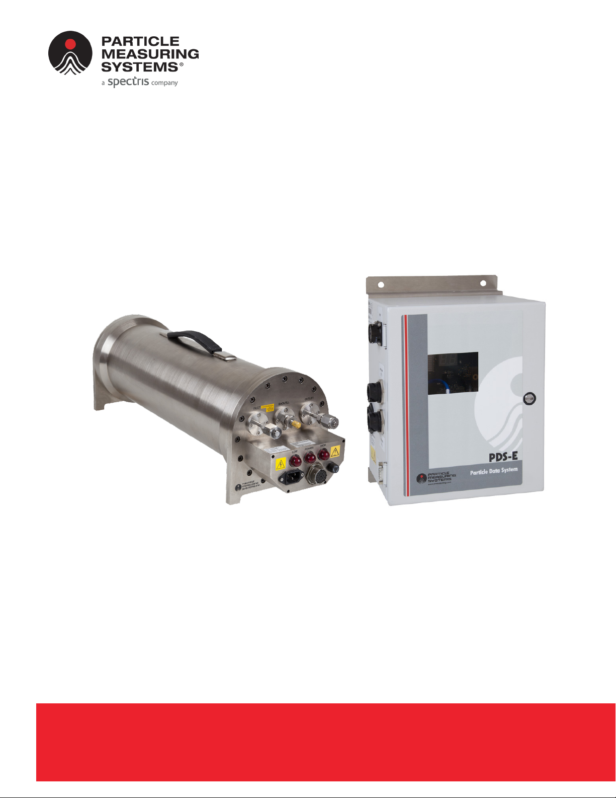
HPGP™ 101-C with PDS-E
Ultra High Purity Gas Particle Counter
and Particle Detection System
P/N 1000025203
OPERATIONS MANUAL
Without measurement there is no control

HEADQUARTERS
5475 Airport Blvd
Boulder, Colorado 80301 USA
T: +1 303 443 7100
Instrument Service & Support
T: +1 800 557 6363
Customer Response Center
T: +1 877 475 3317
E: Info@pmeasuring.com
GLOBAL OFFICES
AUSTRIA
T: +43 1 71 728 285
E: pmsaustria@pmeasuring.com
BENELUX
T: +32 10 23 71 56
E: pmsbelgium@pmeasuring.com
BRAZIL
T: +55 11 5188 8227
E: pmsbrazil@pmeasuring.com
CHINA
T: +86 21 6113 3600
E: pmschina@pmeasuring.com
FRANCE
T: +33 (0)1 60 10 32 96
E: pmsfranc[email protected]
GERMANY
T: +49 6151 6671 632
E: pmsgermany@pmeasuring.com
ITALY
T: +39 06 9053 0130
E: pmssrl@pmeasuring.com
JAPAN
T: +81 44 589 3498
E: pmsjapan@pmeasuring.com
KOREA
T: +82 31 286 5790
E: pmskorea@pmeasuring.com
MEXICO
T: +52 55 2271 5106
E: pmsmexic[email protected]om
NORDIC
T: +45 707 028 55
E: pmsnordic@pmeasuring.com
PUERTO RICO
T: +1 787 718 9096
E: pmspuertoric[email protected]om
SINGAPORE
T: +65 6496 0330
E: pmssingapore@pmeasuring.com
SWITZERLAND
T: +41 71 987 01 01
E: pmsswitzerland@pmeasuring.com
TAIWAN
T: +886-3-5525300 Ext: 301
E: pmstaiwan@pmeasuring.com
HPGP™ 101-C RoHS with PDS-E
Ultra High Purity Gas Particle Counter
and Particle Detection System
Operations Manual
P/N 1000025203 Rev D

ii HPGP™ 101-C RoHS with PDS-E Operations Manual
HPGPTM 101-C RoHS with PDS-E Operations Manual
P/N 1000025203 Rev D
© 2022 Particle Measuring Systems, Inc.
All rights reserved.
Cajon® and Swagelok® are registered trademarks of the Swagelok Company.
Viton® is a registered trademark of Dupont Dow Elastomers L.L.C.
All trademarks appearing in this manual are the property of their respective owners.
This confidential document contains proprietary information, which is protected by
copyright. All rights are reserved. No part of this document may be reproduced,
distributed, or transmitted in any form without the prior written consent of Particle
Measuring Systems. The information contained in this document is subject to change
without notice.
Quality Statement
The Quality Policy of Particle Measuring Systems is to strive to meet or exceed the
needs and expectations of our customers, and to align the activities of all employees
with the common focus of customer satisfaction through continuous improvement in
the quality of our products and services.
Environmental Information
This equipment must be properly disposed of at end-of-life by means of an
authorized waste management system. Contact our Customer Response Center at
(877) 475-3317 or (303) 443-7100 (International Telephone +1 3034437100) for
dismantling and disposal information.
DO NOT REPRODUCE OR DISTRIBUTE CONFIDENTIAL DOCUMENT

HPGP™ 101-C RoHS with PDS-E Operations Manual iii
Manual Conventions
It is important that you observe cautions and warnings while performing the
procedures described in this manual. Caution and warning labels are located on and
inside the instrument to alert you to potentially hazardous conditions. Please
familiarize yourself with this information.
WARNING
A warning in the text is used to notify the user of the potential for bodily injury or death.
CAUTION
A caution in the text is used to highlight an item that if not done, or incorrectly done, could
damage the instrument and/or any materials or devices affected by the instrument.
– — NOTICE — –
A notice in the text is an instructional communication regarding requirements or policies
issued by Particle Measuring Systems.
NOTE: A note in the text is used to highlight an item that is of operational importance
to the user.

iv HPGP™ 101-C RoHS with PDS-E Operations Manual
and Declaration of Conformity
Application of Council Directive(s): CE 2014/30/EU, 2014/53/EU, 2014/35/EU, RoHS 2011/65/EU,
2015/863
UKCA Electromagnetic Compatibility Regulations 2016,
Electrical Equipment (Safety) Regulations 2016
The Restriction of the Use of Certain Hazardous Substances in
Electrical and Electronic Equipment Regulations 2012
Standard(s) to which Conformity is Declared: EMC EN 61326-1:2013
S.I. 2016 No. 1091
Safety EN61010-1: 2010, 3rd, Ed., S.I. 2016 No. 1101, EN60825-1:2014
RoHS BS EN 63000:2018
Manufacturer’s Name: Particle Measuring Systems, Inc.
Manufacturer’s Address: 5475 Airport Boulevard
Boulder, CO 80301 USA
Manufacturer’s Telephone/FAX: + 1 3034437100 / + 1 3034496870
Distributor’s Name: Particle Measuring Systems, S.R.L.
Distributor’s Address Via di Grotte Portella 34
00044 Frascati (Roma) ITALY
Distributor’s Telephone/FAX: + 39 06 90530130 / + 39 06 9051315
Type of Equipment: Particle Monitoring
Model No: HPGP 101-C RoHS with PDS-E
I, the undersigned, hereby declare that the equipment specified above conforms to the above Directive(s) and Standard(s).
Signature: Signature:
Full Name: Scott MacLaughlin Full Name: Frank Panofen
Position: Director of Engineering Position: Marketing Manager, Life Sciences
Place: Boulder Date: April 25, 2022 Place: Rome Date: April 25, 2022
CAUTION
All I/O cables and accessories must meet current factory specifications in order for this unit to
remain in compliance with CE marking requirements. Consult the factory for details.
If the equipment is used in a manner not specified by the manufacturer, the protection provided
by the equipment may be impaired.

HPGP™ 101-C RoHS with PDS-E Operations Manual v
Table of Contents
List of Figures - - - - - - - - - - - - - - - - - - - - - - - - - - - - - - - - - - - - - - - - - - - - - - - - - - - - - - ix
List of Tables - - - - - - - - - - - - - - - - - - - - - - - - - - - - - - - - - - - - - - - - - - - - - - - - - - - - - - - xi
Chapter 1: Introduction - - - - - - - - - - - - - - - - - - - - - - - - - - - - - - - - - - - - - - - - - - - - - 1-1
Overview - - - - - - - - - - - - - - - - - - - - - - - - - - - - - - - - - - - - - - - - - - - - - - - - - 1-1
HPGP 101-C Specifications - - - - - - - - - - - - - - - - - - - - - - - - - - - - - - - - - - - 1-5
HPGP 101-C Front Panel Features - - - - - - - - - - - - - - - - - - - - - - - - - - - - - - 1-6
HPGP 101-C Materials - - - - - - - - - - - - - - - - - - - - - - - - - - - - - - - - - - - - - - - 1-7
PDS-E Specifications - - - - - - - - - - - - - - - - - - - - - - - - - - - - - - - - - - - - - - - - 1-8
PDS-E Side Panel Features- - - - - - - - - - - - - - - - - - - - - - - - - - - - - - - - - - - - 1-8
PDS-E Materials - - - - - - - - - - - - - - - - - - - - - - - - - - - - - - - - - - - - - - - - - - - - 1-9
Chapter 2: HPGP 101-C Safety Considerations - - - - - - - - - - - - - - - - - - - - - - - - - - - 2-1
Safety Sheet - - - - - - - - - - - - - - - - - - - - - - - - - - - - - - - - - - - - - - - - - - - - - - - 2-3
Warning Labels- - - - - - - - - - - - - - - - - - - - - - - - - - - - - - - - - - - - - - - - - - 2-3
Chapter 3: Unpacking and Installation- - - - - - - - - - - - - - - - - - - - - - - - - - - - - - - - - - 3-1
Unpacking - - - - - - - - - - - - - - - - - - - - - - - - - - - - - - - - - - - - - - - - - - - - - - - - 3-1
HPGP 101-C Unpacking - - - - - - - - - - - - - - - - - - - - - - - - - - - - - - - - - - - 3-1
PDS-E Unpacking - - - - - - - - - - - - - - - - - - - - - - - - - - - - - - - - - - - - - - - - 3-2
Recycling - - - - - - - - - - - - - - - - - - - - - - - - - - - - - - - - - - - - - - - - - - - - - - - - - 3-3
Installation of HPGP 101-C- - - - - - - - - - - - - - - - - - - - - - - - - - - - - - - - - - - - 3-4
Installing the PDS-E Wall Mount - - - - - - - - - - - - - - - - - - - - - - - - - - - - - - - 3-6
Installing the PDS-E Rack Mount - - - - - - - - - - - - - - - - - - - - - - - - - - - - - - - 3-7
Configuration - - - - - - - - - - - - - - - - - - - - - - - - - - - - - - - - - - - - - - - - - - - - - - 3-8
Chapter 4: PDS-E Communications Setup - - - - - - - - - - - - - - - - - - - - - - - - - - - - - - - 4-1
Serial Setup Interface - - - - - - - - - - - - - - - - - - - - - - - - - - - - - - - - - - - - - - - 4-2
Serial Configuration Commands - - - - - - - - - - - - - - - - - - - - - - - - - - - - - - - 4-3
Alphabetical List of Serial Commands- - - - - - - - - - - - - - - - - - - - - - - - - - - 4-4
Telnet - - - - - - - - - - - - - - - - - - - - - - - - - - - - - - - - - - - - - - - - - - - - - - - - - 4-13
Ethernet Communication Set Up- - - - - - - - - - - - - - - - - - - - - - - - - - - - - - - 4-14
Set Ethernet Parameters - - - - - - - - - - - - - - - - - - - - - - - - - - - - - - - - - - 4-14
Additional Settings- - - - - - - - - - - - - - - - - - - - - - - - - - - - - - - - - - - - - - - 4-15
Ethernet Settings Record- - - - - - - - - - - - - - - - - - - - - - - - - - - - - - - - - - 4-15
PMS Protocol (Facility Net) Configuration and Operation - - - - - - - - - - - 4-16
Modbus Configuration and Operation- - - - - - - - - - - - - - - - - - - - - - - - - - - 4-16
OPC Configuration and Operation- - - - - - - - - - - - - - - - - - - - - - - - - - - - - - 4-17

vi HPGP™ 101-C RoHS with PDS-E Operations Manual
:
Retro Operational Mode - - - - - - - - - - - - - - - - - - - - - - - - - - - - - - - - - - - - - 4-18
Chapter 5: Performance Check - - - - - - - - - - - - - - - - - - - - - - - - - - - - - - - - - - - - - - - 5-1
Particle Size Calibration Check - - - - - - - - - - - - - - - - - - - - - - - - - - - - - - - - 5-1
Reference Voltage - - - - - - - - - - - - - - - - - - - - - - - - - - - - - - - - - - - - - - - - - - 5-1
Air Flowrate Calibration Check - - - - - - - - - - - - - - - - - - - - - - - - - - - - - - - - 5-1
Zero Count Check - - - - - - - - - - - - - - - - - - - - - - - - - - - - - - - - - - - - - - - - - - 5-2
Chapter 6: Maintenance and Troubleshooting - - - - - - - - - - - - - - - - - - - - - - - - - - - 6-1
Low Reference Voltage Background - - - - - - - - - - - - - - - - - - - - - - - - - - - - 6-1
Checking for Leaks- - - - - - - - - - - - - - - - - - - - - - - - - - - - - - - - - - - - - - - - - - 6-4
Transient Induced Counts - - - - - - - - - - - - - - - - - - - - - - - - - - - - - - - - - - - - 6-4
Nitrogen Purging and Backfilling the Probe Containment Vessel - - - - - 6-5
Pressure Method of Purging and Backfilling/Pressurizing - - - - - - - - 6-5
Vacuum Method of Purging and Backfilling - - - - - - - - - - - - - - - - - - - 6-7
Required items - - - - - - - - - - - - - - - - - - - - - - - - - - - - - - - - - - - - - - 6-7
Appendix A: International Precautions - - - - - - - - - - - - - - - - - - - - - - - - - - - - - - - - - A-1
WARNING - - - - - - - - - - - - - - - - - - - - - - - - - - - - - - - - - - - - - - - - - - - - - - - - - A-1
AVERTISSEMENT - - - - - - - - - - - - - - - - - - - - - - - - - - - - - - - - - - - - - - - - - - - A-1
WARNUNG - - - - - - - - - - - - - - - - - - - - - - - - - - - - - - - - - - - - - - - - - - - - - - - - A-1
ATTENZIONE - - - - - - - - - - - - - - - - - - - - - - - - - - - - - - - - - - - - - - - - - - - - - - A-1
ADVERTENCIA - - - - - - - - - - - - - - - - - - - - - - - - - - - - - - - - - - - - - - - - - - - - - A-1
Hazard Symbols- - - - - - - - - - - - - - - - - - - - - - - - - - - - - - - - - - - - - - - - - - - - A-2
Symboles de risque - - - - - - - - - - - - - - - - - - - - - - - - - - - - - - - - - - - - - - - - - A-2
Warnschilder - - - - - - - - - - - - - - - - - - - - - - - - - - - - - - - - - - - - - - - - - - - - - - A-3
Simboli di pericolo- - - - - - - - - - - - - - - - - - - - - - - - - - - - - - - - - - - - - - - - - - A-3
Simbolos de peligro- - - - - - - - - - - - - - - - - - - - - - - - - - - - - - - - - - - - - - - - - A-3
Appendix B: Modbus Protocol - - - - - - - - - - - - - - - - - - - - - - - - - - - - - - - - - - - - - - - - B-1
Modbus Overview - - - - - - - - - - - - - - - - - - - - - - - - - - - - - - - - - - - - - - - - - - B-1
Input Registers- - - - - - - - - - - - - - - - - - - - - - - - - - - - - - - - - - - - - - - - - - - - - B-2
Holding Registers- - - - - - - - - - - - - - - - - - - - - - - - - - - - - - - - - - - - - - - - - - - B-6
Coils - - - - - - - - - - - - - - - - - - - - - - - - - - - - - - - - - - - - - - - - - - - - - - - - - - - - - B-7
Data Packet Processing - - - - - - - - - - - - - - - - - - - - - - - - - - - - - - - - - - - - - - B-8
Associated Values for Specific Registry Entries- - - - - - - - - - - - - - - - - - - - B-8
Appendix C: OPC Communications - - - - - - - - - - - - - - - - - - - - - - - - - - - - - - - - - - - - C-1
Connecting a PC to the PDS-E OPC Server - - - - - - - - - - - - - - - - - - - - - - - C-1
PDS-E OPC Data Access Tags- - - - - - - - - - - - - - - - - - - - - - - - - - - - - - - - - - C-2
Appendix D: Ethernet Communications Overview - - - - - - - - - - - - - - - - - - - - - - - - D-1
IT Department - - - - - - - - - - - - - - - - - - - - - - - - - - - - - - - - - - - - - - - - - - - - - D-1
Ethernet Addressing Basics - - - - - - - - - - - - - - - - - - - - - - - - - - - - - - - - - - - D-1

:
HPGP™ 101-C RoHS with PDS-E Operations Manual vii
IP Address- - - - - - - - - - - - - - - - - - - - - - - - - - - - - - - - - - - - - - - - - - - - - - D-2
Network Mask- - - - - - - - - - - - - - - - - - - - - - - - - - - - - - - - - - - - - - - - - - - D-2
Gateway Address - - - - - - - - - - - - - - - - - - - - - - - - - - - - - - - - - - - - - - - - D-3
Multicast Address- - - - - - - - - - - - - - - - - - - - - - - - - - - - - - - - - - - - - - - - D-3
MAC Address - - - - - - - - - - - - - - - - - - - - - - - - - - - - - - - - - - - - - - - - - - - - - - D-3
Static IP Addresses versus DHCP Addresses - - - - - - - - - - - - - - - - - - - - - - D-4
Troubleshooting Ethernet Connectivity - - - - - - - - - - - - - - - - - - - - - - - - - D-5
Instrument to Laptop Ethernet Setup - - - - - - - - - - - - - - - - - - - - - - - - - - - D-7
Method 1: Modifying the IP Settings on a PC - - - - - - - - - - - - - - - - - - - D-7
Method 2: Modifying the Settings on an Instrument - - - - - - - - - - - - - D-10
Appendix E: Serial Communications Overview - - - - - - - - - - - - - - - - - - - - - - - - - - - E-1
Adapters and Cables - - - - - - - - - - - - - - - - - - - - - - - - - - - - - - - - - - - - - - - - E-2
Useful Serial Adapters - - - - - - - - - - - - - - - - - - - - - - - - - - - - - - - - - - - - E-2
USB Serial Port Adapter - - - - - - - - - - - - - - - - - - - - - - - - - - - - - - - - - - - E-3
USB Driver for Windows - - - - - - - - - - - - - - - - - - - - - - - - - - - - - - - E-3
Serial Cable - - - - - - - - - - - - - - - - - - - - - - - - - - - - - - - - - - - - - - - - - - - - E-3
RJ-12 Cable and Adapter - - - - - - - - - - - - - - - - - - - - - - - - - - - - - - - - - - E-4
Connector Signals - - - - - - - - - - - - - - - - - - - - - - - - - - - - - - - - - - - - - - - - - - E-5
Communication Software Options - - - - - - - - - - - - - - - - - - - - - - - - - - - - - E-6
HyperTerminal - - - - - - - - - - - - - - - - - - - - - - - - - - - - - - - - - - - - - - - - - - E-6
PuTTY - - - - - - - - - - - - - - - - - - - - - - - - - - - - - - - - - - - - - - - - - - - - - - - - - E-7
Tera Term- - - - - - - - - - - - - - - - - - - - - - - - - - - - - - - - - - - - - - - - - - - - - - E-8
Communications Configuration - - - - - - - - - - - - - - - - - - - - - - - - - - - - - - - E-9
ENODE Specific Settings - - - - - - - - - - - - - - - - - - - - - - - - - - - - - - - - - - E-9
Troubleshooting Serial Communications - - - - - - - - - - - - - - - - - - - - - - - - E-9
No Communications - - - - - - - - - - - - - - - - - - - - - - - - - - - - - - - - - - - - - E-9
Dropped Characters or Strange Characters- - - - - - - - - - - - - - - - - - - - E-9
Unexpected Characters - - - - - - - - - - - - - - - - - - - - - - - - - - - - - - - - - - - E-9
Appendix F: 有毒或有害的物质和元素 PDS-E - - - - - - - - - - - - - - - - - - - - - - - - - - - - F-1
Appendix G: 有毒或有害的物质和元素 HPGP 101-C - - - - - - - - - - - - - - - - - - - - - - G-1
Index - - - - - - - - - - - - - - - - - - - - - - - - - - - - - - - - - - - - - - - - - - - - - - - - - - - - - - - - - Index-1

viii HPGP™ 101-C RoHS with PDS-E Operations Manual
:
This page is intentionally left blank.

HPGP™ 101-C RoHS with PDS-E Operations Manual ix
List of Figures
Chapter 1: Introduction - - - - - - - - - - - - - - - - - - - - - - - - - - - - - - - - - - - - - - - - - - - - - - - - - - - 1-1
Figure 1-1 The Particle Measuring Systems PDS-E and HPGP 101-C instruments - - - - - - - - - - - - - - 1-1
Figure 1-2 HPGP 101-C Dimensions - - - - - - - - - - - - - - - - - - - - - - - - - - - - - - - - - - - - - - - - - - - - - - - - - 1-2
Figure 1-3 HPGP 101-C flow diagram - - - - - - - - - - - - - - - - - - - - - - - - - - - - - - - - - - - - - - - - - - - - - - - - 1-3
Figure 1-4 HPGP 101-C front panel - - - - - - - - - - - - - - - - - - - - - - - - - - - - - - - - - - - - - - - - - - - - - - - - - - 1-6
Figure 1-5 PDS-E side panel connectors - - - - - - - - - - - - - - - - - - - - - - - - - - - - - - - - - - - - - - - - - - - - - - 1-9
Chapter 2: HPGP 101-C Safety Considerations - - - - - - - - - - - - - - - - - - - - - - - - - - - - - - - - - 2-1
Chapter 3: Unpacking and Installation - - - - - - - - - - - - - - - - - - - - - - - - - - - - - - - - - - - - - - - 3-1
Figure 3-1 HPGP 101-C shipping kit - - - - - - - - - - - - - - - - - - - - - - - - - - - - - - - - - - - - - - - - - - - - - - - - - 3-1
Figure 3-2 PDS-E shipping kitRecycling - - - - - - - - - - - - - - - - - - - - - - - - - - - - - - - - - - - - - - - - - - - - - - 3-2
Figure 3-3 Attaching the Fill Gauge- - - - - - - - - - - - - - - - - - - - - - - - - - - - - - - - - - - - - - - - - - - - - - - - - - 3-4
Figure 3-4 PDS-E with wall mounting brackets- - - - - - - - - - - - - - - - - - - - - - - - - - - - - - - - - - - - - - - - - 3-6
Figure 3-5 Rack mount PDS-E (rear) - - - - - - - - - - - - - - - - - - - - - - - - - - - - - - - - - - - - - - - - - - - - - - - - - 3-7
Figure 3-6 19” Rack mount PDS-E (front) - - - - - - - - - - - - - - - - - - - - - - - - - - - - - - - - - - - - - - - - - - - - - 3-7
Chapter 4: PDS-E Communications Setup - - - - - - - - - - - - - - - - - - - - - - - - - - - - - - - - - - - - - 4-1
Figure 4-1 Communication ports on side panel of the PDS-E. - - - - - - - - - - - - - - - - - - - - - - - - - - - - - 4-1
Chapter 5: Performance Check - - - - - - - - - - - - - - - - - - - - - - - - - - - - - - - - - - - - - - - - - - - - - 5-1
Chapter 6: Maintenance and Troubleshooting - - - - - - - - - - - - - - - - - - - - - - - - - - - - - - - - - 6-1
Figure 6-1 HPGP 101-C Optical System diagram - - - - - - - - - - - - - - - - - - - - - - - - - - - - - - - - - - - - - - - 6-2
Figure 6-2 HPGP 101-C cylinder assembly - - - - - - - - - - - - - - - - - - - - - - - - - - - - - - - - - - - - - - - - - - - - 6-3
Figure 6-3 Detail of HPGP 101-C cylinder assembly - - - - - - - - - - - - - - - - - - - - - - - - - - - - - - - - - - - - - 6-3
Appendix A: International Precautions - - - - - - - - - - - - - - - - - - - - - - - - - - - - - - - - - - - - - - - A-1
Appendix B: Modbus Protocol - - - - - - - - - - - - - - - - - - - - - - - - - - - - - - - - - - - - - - - - - - - - - - B-1
Appendix C: OPC Communications - - - - - - - - - - - - - - - - - - - - - - - - - - - - - - - - - - - - - - - - - - C-1
Appendix D: Ethernet Communications Overview - - - - - - - - - - - - - - - - - - - - - - - - - - - - - - D-1
Figure D-1 Ethernet port connectivity LED - - - - - - - - - - - - - - - - - - - - - - - - - - - - - - - - - - - - - - - - - - - - D-5
Figure D-2 Example for ping test - - - - - - - - - - - - - - - - - - - - - - - - - - - - - - - - - - - - - - - - - - - - - - - - - - - D-6
Figure D-3 Example for ipconfig command - - - - - - - - - - - - - - - - - - - - - - - - - - - - - - - - - - - - - - - - - - - D-6
Figure D-4 Local Area Connection Properties window - - - - - - - - - - - - - - - - - - - - - - - - - - - - - - - - - D-8
Figure D-5 The IP address and subnet mask defined - - - - - - - - - - - - - - - - - - - - - - - - - - - - - - - - - - - - D-9

x HPGP™ 101-C RoHS with PDS-E Operations Manual
:
Appendix E: Serial Communications Overview - - - - - - - - - - - - - - - - - - - - - - - - - - - - - - - - - E-1
Figure E-1 USB serial adapter - - - - - - - - - - - - - - - - - - - - - - - - - - - - - - - - - - - - - - - - - - - - - - - - - - - - - - E-3
Figure E-2 Serial cable with DE-9 male and female connectors - - - - - - - - - - - - - - - - - - - - - - - - - - - - E-3
Figure E-3 RJ-12 adapter and cable - - - - - - - - - - - - - - - - - - - - - - - - - - - - - - - - - - - - - - - - - - - - - - - - - E-4
Figure E-4 HyperTerminal screen - - - - - - - - - - - - - - - - - - - - - - - - - - - - - - - - - - - - - - - - - - - - - - - - - - E-6
Figure E-5 PuTTY Configuration screen - - - - - - - - - - - - - - - - - - - - - - - - - - - - - - - - - - - - - - - - - - - - - - E-7
Figure E-6 PuTTY Main screen- - - - - - - - - - - - - - - - - - - - - - - - - - - - - - - - - - - - - - - - - - - - - - - - - - - - - - E-7
Figure E-7 Tera Term Setup window - - - - - - - - - - - - - - - - - - - - - - - - - - - - - - - - - - - - - - - - - - - - - - - - E-8
Figure E-8 Tera Term Main window (colors reversed) - - - - - - - - - - - - - - - - - - - - - - - - - - - - - - - - - - - E-8
Appendix F: 有毒或有害的物质和元素 PDS-E - - - - - - - - - - - - - - - - - - - - - - - - - - - - - F-1
Appendix G: 有毒或有害的物质和元素 HPGP 101-C - - - - - - - - - - - - - - - - - - - - - - - - G-1

HPGP™ 101-C RoHS with PDS-E Operations Manual xi
List of Tables
Chapter 1: Introduction - - - - - - - - - - - - - - - - - - - - - - - - - - - - - - - - - - - - - - - - - - - - - - - - - - - 1-1
Table 1-1 HPGP 101-C Specifications - - - - - - - - - - - - - - - - - - - - - - - - - - - - - - - - - - - - - - 1-5
Table 1-2 HPGP 101-C Materials - - - - - - - - - - - - - - - - - - - - - - - - - - - - - - - - - - - - - - - - - - 1-7
Table 1-3 PDS-E Specifications - - - - - - - - - - - - - - - - - - - - - - - - - - - - - - - - - - - - - - - - - - - 1-8
Table 1-4 PDS-E Materials - - - - - - - - - - - - - - - - - - - - - - - - - - - - - - - - - - - - - - - - - - - - - - - 1-9
Chapter 2: HPGP 101-C Safety Considerations - - - - - - - - - - - - - - - - - - - - - - - - - - - - - - - - - 2-1
Chapter 3: Unpacking and Installation - - - - - - - - - - - - - - - - - - - - - - - - - - - - - - - - - - - - - - - 3-1
Table 3-1 Correction of Flowmeter for Different Gas Molecular Weight- - - - - - - - - - - - 3-8
Chapter 4: PDS-E Communications Setup - - - - - - - - - - - - - - - - - - - - - - - - - - - - - - - - - - - - - 4-1
Table 4-1 Cable pin assignments - - - - - - - - - - - - - - - - - - - - - - - - - - - - - - - - - - - - - - - - - - - - - 4-2
Table 4-2 Communication settings - - - - - - - - - - - - - - - - - - - - - - - - - - - - - - - - - - - - - - - - 4-2
Chapter 5: Performance Check - - - - - - - - - - - - - - - - - - - - - - - - - - - - - - - - - - - - - - - - - - - - - 5-1
Table 5-1 Correction of Flowmeter for Different Gas Molecular Weight- - - - - - - - - - - - 5-2
Chapter 6: Maintenance and Troubleshooting - - - - - - - - - - - - - - - - - - - - - - - - - - - - - - - - - 6-1
Appendix A: International Precautions - - - - - - - - - - - - - - - - - - - - - - - - - - - - - - - - - - - - - - - A-1
Appendix B: Modbus Protocol - - - - - - - - - - - - - - - - - - - - - - - - - - - - - - - - - - - - - - - - - - - - - - B-1
Table B-1 Input register – configuration - - - - - - - - - - - - - - - - - - - - - - - - - - - - - - - - - - - - - - - B-3
Table B-2 Input register – data packet - - - - - - - - - - - - - - - - - - - - - - - - - - - - - - - - - - - - - B-4
Table B-3 Holding registers - - - - - - - - - - - - - - - - - - - - - - - - - - - - - - - - - - - - - - - - - - - - - - B-6
Table B-4 Coils- - - - - - - - - - - - - - - - - - - - - - - - - - - - - - - - - - - - - - - - - - - - - - - - - - - - - - - - B-7
Table B-5 Associated values for specific registry entries - - - - - - - - - - - - - - - - - - - - - - - B-8
Appendix C: OPC Communications - - - - - - - - - - - - - - - - - - - - - - - - - - - - - - - - - - - - - - - - - - C-1
Table C-1 PDS-E OPC Data Access Tags - - - - - - - - - - - - - - - - - - - - - - - - - - - - - - - - - - - - - - - - C-2
Appendix D: Ethernet Communications Overview - - - - - - - - - - - - - - - - - - - - - - - - - - - - - - D-1
Table D-1 Private IPv4 Network Ranges - - - - - - - - - - - - - - - - - - - - - - - - - - - - - - - - - - - - - - - D-2
Table D-2 Default Network Mask Values - - - - - - - - - - - - - - - - - - - - - - - - - - - - - - - - - - - - D-2
Appendix E: Serial Communications Overview - - - - - - - - - - - - - - - - - - - - - - - - - - - - - - - - - E-1
Table E-1 Recommended Serial Adapters - - - - - - - - - - - - - - - - - - - - - - - - - - - - - - - - - - - - - - E-2
Table E-2 Standard PC Serial Port (DE-9) - - - - - - - - - - - - - - - - - - - - - - - - - - - - - - - - - - - E-5

xii HPGP™ 101-C RoHS with PDS-E Operations Manual
:
Table E-3 RJ-12 Instrument Connector- - - - - - - - - - - - - - - - - - - - - - - - - - - - - - - - - - - - - E-5
Table E-4 Communication parameters- - - - - - - - - - - - - - - - - - - - - - - - - - - - - - - - - - - - - E-9
Appendix F: 有毒或有害的物质和元素 PDS-E - - - - - - - - - - - - - - - - - - - - - - - - - - - - - F-1
Appendix G: 有毒或有害的物质和元素 HPGP 101-C - - - - - - - - - - - - - - - - - - - - - - - - G-1
HPGP™ 101-C RoHS with PDS-E Operations Manual 1-1
Chapter 1
Introduction
Overview
The HPGP™ 101-C monitors particles in gas lines operating at line pressures of 40 –150
PSIG to measure particle contamination with up to 8 size channels of: 0.1, 0.2, 0.3, 0.5,
1.0, 2.0, 3.0, and 5.0 µm. HPGP 101-C is compatible with Ar, CO2, He, H2, Ne, N2, O2, and
other bulk gases (contact PMS for specific applications).
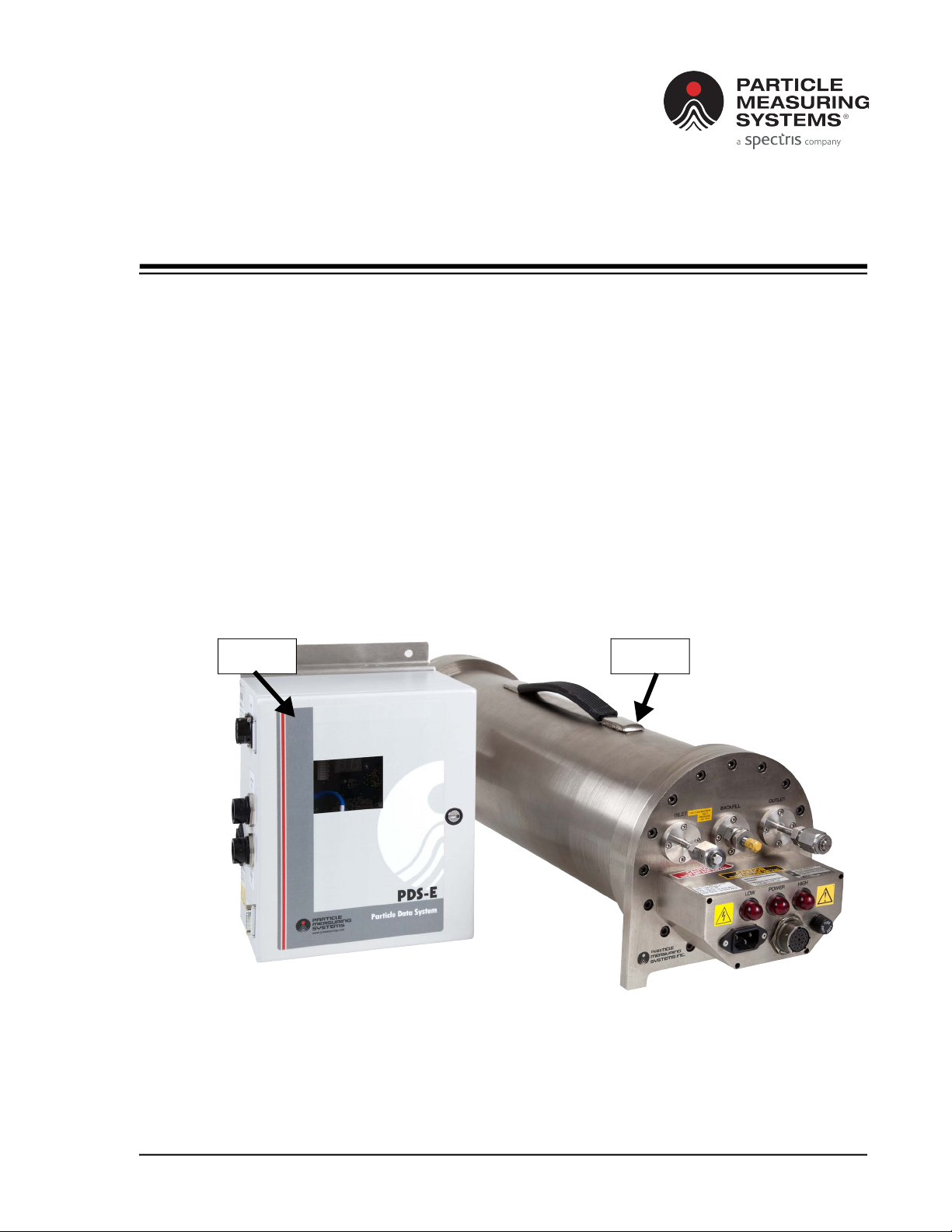
The Particle Data System - Ethernet (PDS-E) aggregates data from the HPGP 101-C and
reports to a connected or networked PC. The PDS-E is designed to be the controller
and data interface between the HPGP 101-C and any external network (see Figure 1-1).
Figure 1-1 The Particle Measuring Systems PDS-E and HPGP 101-C instruments
HPGPPDS-E

1-2 HPGP™ 101-C RoHS with PDS-E Operations Manual
Chapter 1 : Introduction Overview
The PDS-E allows data communication for multiple data management options via:
• Ethernet (via PMS protocol) for communication to Facility Net (PMS data
management software)
• Modbus via Ethernet
• OPC via Ethernet
• RS-232 (bi-directional)
The volumetric sample flowrate of 0.1 SCFM (2.8 LPM) is regulated by an internal mass
flow controller. The HPGP 101-C delivers a counting efficiency of > 50% at 0.14 µm, zero
count level < 2/ft3 or < 0.2/min, and has a maximum concentration of 3,000 counts per
cubic foot. All other specifications can be found in Table 1-1, “HPGP 101-C
Specifications” on page 1-5.
The entire HPGP 101-C assembly, with dimensions and form factors, can be seen in
Figure 1-2. The probe is contained in a cylindrical containment vessel which serves as
a safety containment envelope and should be opened only by trained Particle
Measurement Systems representatives.
Figure 1-2 HPGP 101-C Dimensions
Overview Chapter 1 : Introduction
HPGP™ 101-C RoHS with PDS-E Operations Manual 1-3
All input and output interfaces are located on the front panel to provide easy
connection access. The optics, electronics, and other flow hardware are internally
located within the HPGP 101-C. All power supplies are modular units and the low
voltage supplies have short-circuit protection. The laser high-voltage supply is sealed
and shielded.
The HPGP 101-C uses a HeNe, 633-nm laser source which is Class I per EN60825-1 and,
internally, a Class III B laser per EN60825-1. The PDS-E accurately monitors the laser
reference voltage (input between 0 - 10 V). The laser reference voltage is a
measurement of the passive cavity laser power. A certain level must be maintained to
have an adequate signal-to-noise ratio for correct sizing accuracy. A minimum
reference level of 5.5 volts at operating pressure is considered adequate.
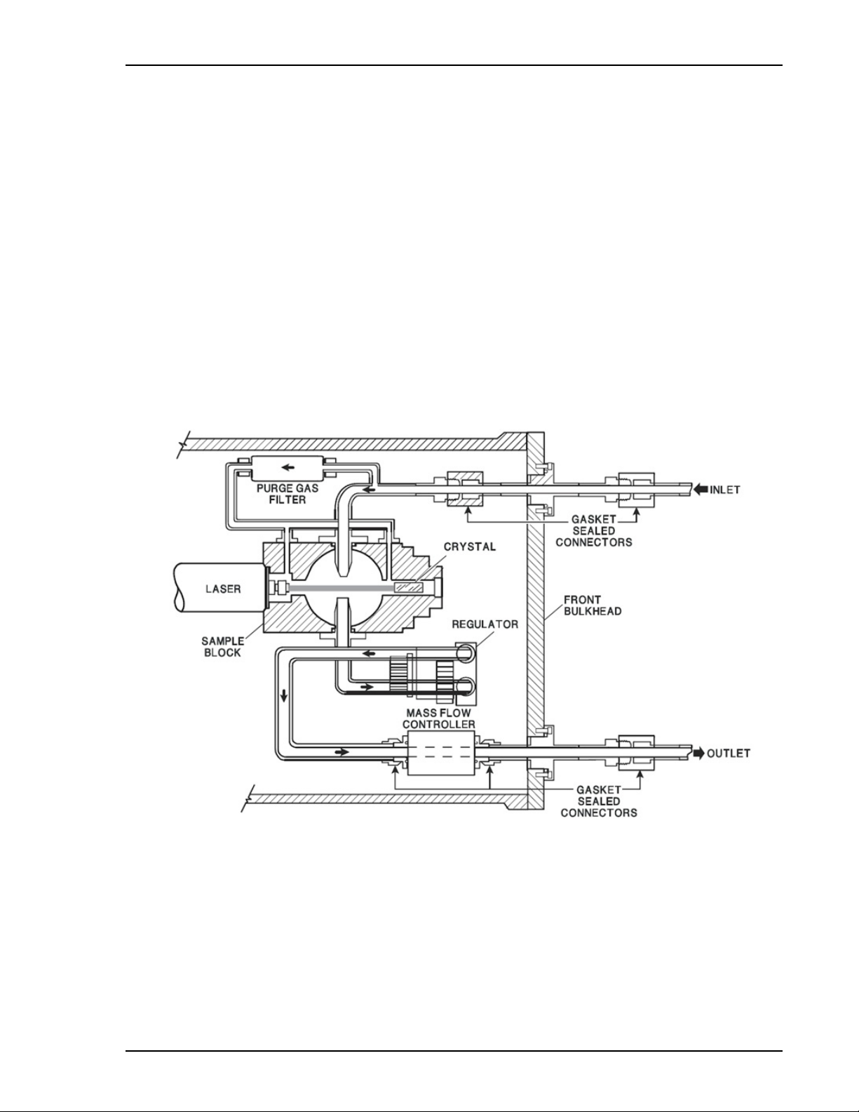
All wetted surfaces are either 316 L stainless steel, glass, or an inert polymer with VCR
fittings through the aerosol inlet, and Swagelok® fittings from the aerosol outlet back
to the front panel.The flow path for the high pressure gas probe is shown in Figure 1-3.
Figure 1-3 HPGP 101-C flow diagram
A mass flow controller in the sample outlet flow stream provides 0.1 CFM of gas flow at
standard temperature and pressure (STP). It controls the flow to within ± 2%
independent of the inlet line pressure for the 40 –150 PSIG working range. The mass
flow controller requires a specific control voltage for the particular gas being sampled.
If the PDS-E is used, it provides the control voltage for the mass flow controller.

1-4 HPGP™ 101-C RoHS with PDS-E Operations Manual
Chapter 1 : Introduction Overview
The laser reference voltage is a measurement of the passive cavity laser power. A
certain level must be maintained to have adequate signal-to-noise ratio for correct
sizing accuracy. A minimum reference level of 5.5 volts at operating pressure is
considered adequate. All other specifications can be found in Table 1-3, “PDS-E
Specifications” on page 1-8.

HPGP 101-C Specifications Chapter 1 : Introduction
HPGP™ 101-C RoHS with PDS-E Operations Manual 1-5
HPGP 101-C Specifications
Table 1-1 HPGP 101-C Specifications
Size range 0.1 – 5.0 µm
Size channels 8 with thresholds at 0.1, 0.2, 0.3, 0.5, 1.0, 2.0, 3.0, and 5.0 µm
Flow rate 0.1 SCFM (2.8 LPM)
Flow is regulated by mass flow controller located downstream of the
sampling cavity.
Sample volume 0.1 SCFM (2.8 LPM)
Counting efficiency > 50% at 0.14 µm
Zero count level < 2/ft3 or < 0.2/min
Maximum concentration 3,000/ft3
Operating pressure 40 – 150 PSIG
Concentration 3,000 per cubic foot
Compatible gases Air, Ar, CO2, He, H2, Ne, N2, O2, and other bulk gases.
Toxic gases Particle Measuring Systems, Inc. uses oxygen compatible procedures
when assembling the laser bench and plumbing (de-greasing
mechanical parts, inspection with black light, etc.); however, Particle
Measuring Systems, Inc. will not assume any liability relating to user or
product when sampling toxic gases.
Construction material All wetted surfaces are either 316 L stainless steel, glass, or inert
polymer.
Laser source HeNe, 633 nm
Laser classification Class I per EN60825-1
Internally, a Class III B laser is used, per EN60825-1
Installation requirements Indoor use only
Pollution degree 2
Over-voltage Category II
Ordinary protection (Not protected against harmful ingress of
moisture.)
Class I Equipment (Electrical grounding is required for safety.)
Data communications Differential line drivers
Data system compatibility PDS-E
Environment Temperature: 32 – 113 °F (0 – 45 °C)
Humidity: 0–95% non-condensing
Maximum altitude: 9,842 ft (3,000 m)
Power 240 V, 50 – 60 Hz, 0.5 A
Fuse 0.5A 5 x 20mm T
Dimensions (L,W,H) 26 8 9 in (66 20 22 cm)
Weight 45 lb (20.4 kg)

1-6 HPGP™ 101-C RoHS with PDS-E Operations Manual
Chapter 1 : Introduction HPGP 101-C Front Panel Features
HPGP 101-C Front Panel Features
Figure 1-4 HPGP 101-C front panel
Inlet and Outlet
The gas inlet is on the front left of the HPGP 101-C. Refer to Figure 1-4.
• The gas outlet is on the front right of the HPGP 101-C.
• The user needs to supply the following fittings to use as the mating connectors
for both the inlet and the outlet of the HPGP 101-C.
• PMS-F1163 Cajon (SS-4-VCR-1) (1 each)
• PMS-F1188 Cajon (SS-4-VCR-3-4MTW) (1 each)
• PMS-F1164 Cajon (SS-4-VCR-2-GR) (1 each)
Sensor Cable
The sensor cable for the HPGP 101-C is attached to the lower middle front of the
instrument along with the AC power. Refer to Figure 1-4 on page 1-6.
Fuses
The fuse for the HPGP 101-C is located next to the sensor cable.
Stand/Feet
The HPGP 101-C’s feet are mounted with 6-32 socket head screws. See Figure 1-2 on
page 1-2.

HPGP 101-C Materials Chapter 1 : Introduction
HPGP™ 101-C RoHS with PDS-E Operations Manual 1-7
HPGP 101-C Materials
Table 1-2 HPGP 101-C Materials
Part Material
Laser Optical Bench Assembly
Bench, block body 316 L SS
Screws Stainless steel
Collecting mirrors BK-7 glass
Laser mirrors Quartz
O-rings Viton 75
Fittings (VCR & Swagelok) 316 L SS
Bonding agent Bonding agent VTC-2 UV cured epoxy
Plumbing Assembly
Tubing 316 L SS Stainless Steel
Flow controller
Regulator Assembly
Diaphragm 316 L SS
Valve assembly 316 L SS
Valve seat FKM
Elastometers Fluorocarbon
Flow Controller Assembly
Meter Borosilicate glass
Wetted meter parts 316 SS
Valve assembly Corrosive protected magnetic steel
Seals Viton
Containment Vessel
Cylinder Nickel plated 6061 T6 aluminum
End plates Nickel plated 6061 T6 aluminum
Fasteners (end plate) 1/4-28 x 5/8 Steel alloy Allen head screws. Torque to 100 inch-pounds
Table of contents
Other Spectris Industrial Equipment manuals

Popular Industrial Equipment manuals by other brands

Rupes
Rupes HTE 300 START-UP, OPERATING AND MAINTENANCE INSTRUCTIONS

ITOH DENKI
ITOH DENKI POWER MOLLER IB-P03 Technical documentation

Pepperl+Fuchs
Pepperl+Fuchs LS68 DA-F2 Series manual

Meler
Meler MICRON+ GEAR Series instruction manual

Afag
Afag aflex150 qc quick guide

Siemens
Siemens SIVACON 8PS BD2 Series installation instructions


CAB
CAB 5314 Service manual

Siemens
Siemens SIMATIC RTLS4084T operating instructions

Edge
Edge Rebel 80 General information

Tennsmith
Tennsmith PR16 Installation, operation, parts & maintenance manual

Siemens
Siemens Simcenter SCADAS RS user manual

Mars
Mars Comfort-aire Century Compact HBH Series Installation operation & maintenance