ITOH DENKI POWER MOLLER IB-P03 Guide

IB-P03 cIrcuIt Board
Technical documenTaTion

2
IB-P03 Technical documenTaTion
Original notice - T1.10
CBM-105
CBR-306
HBR-605
CBM-105
CBR-306
HBR-605
CBM-105
CBR-306
CBK-109
CB016B
HBM-201
IB-E
IB-P
Controls Motorized rollers Modules
Standard circuit board
ZPA circuit board
HB510 HB510B
Corresponding circuit board Max load to be conveyed Mechanical brake version
Module circuit board
HBR-605
90° transfer
POP-UP
HBK-608
45° transfer
DC Brushless
Ø50
PM500 XE
Ø60,5
PM605 XE
B&W AS-i 3.0
Wenglor
B&W AS-i 3.0
Wenglor
PM500 XK
PM500 XC
PEPPERL-FUCHS
AS-Interface
B&W AS-i 3.0
PEPPERL-FUCHS
AS-Interface
B&W AS-i 3.0
Ø32
Ø50
Ø60,5
PM320 HS CB018
PM500 FE
CBM-105
HB510
IB-E
PM500 FE-B CB016B
HB510B
PM605 FE
PM605 FE-B CB016B
HB510B
PM605 KT
CBK-109
HBK-608
IB-P
CBM-105
HB510
IB-E
Network controller
IB-E
IB-P
PM500 VE
CBV-108
HBV-609
IB-P
PM605 VE
CBV-108
HBV-609
IB-P
PM500 XP B&W AS-i 3.0
Wenglor
PM605 XP B&W AS-i 3.0
Wenglor
Compatible module / sensor
CBR-306
CB018
CB016 CB016B
CBK-109
CBM-105
CBV-108
Replacing
CB030
HBM-201
solutions
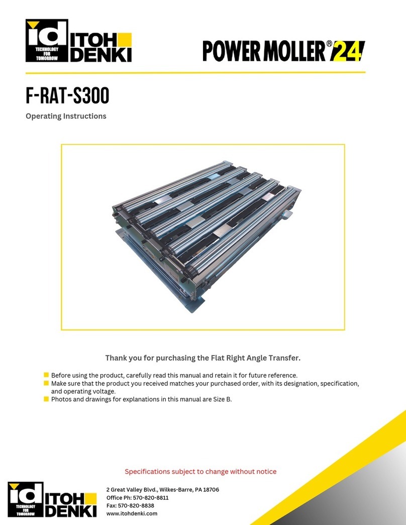
F-RAT-S250
F-RAT-S300
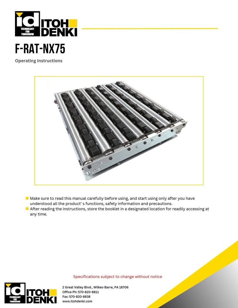
F-RAT-NX75
External
circuit board
Integrated
circuit board
HBV-609
1 - PresenTaTion of The Power moller® ProducT range

3Original notice - T1.10
IB-P03 Technical documenTaTion
1. Presentation of the Power Moller®product range Page 2
2. Summary Page 3
3. Presentation of the IB-P03 circuit board Page 4
3.1 - General description
3.2 - Dimensions
3.3 - General specications
3.4 - Applicable motors
3.5 - Recommended power supply
3.6 - Connectors for IB
Control Power
DRV Power
Sensor cable
Motor cable
LAN cable
4. Wirings Page 9
4.1 - Wirings for power
4.2 - Mounting IB-P03
5. Factory reset procedure Page 11
6. Troubleshooting Page 12
6.1- LED indication on IB-P03 board
6.2- List of errors that can occur in an IB-P03 control board
6.3 - When a motor does not run
6.4 - When communication cannot be established
6.5 - Communication between the PC and IBs (rewall setting)
6.6 - When writing/reading data in a device has failed
6.7 - Notes on using Motor port output
7. Technical data by motorized roller Page 19
7.1 - With PM500VE motorized roller
7.2 - With PM605VE motorized roller
8. Network conguration Page 27
8.1 - Cascade connection
8.2 - Star connection
9. Controlling IB-P03 circuit board Page 28
9.1 - When the PROFINET capable PLC controls IB-P03 circuit board
9.2 - When IB-P03 is used as control and monitored by PROFINET capable PLC
9.3 - When the network is congured only with IB-P03 circuit board
9.4 - When one IB-P03 circuit board controls multiple connected IB-P03 circuit boards
10. Glossary Page 30
11. EU declaration of conformity Page 31
2 - summary

4
IB-P03 Technical documenTaTion
Original notice - T1.10
3.1 - general descriPTion
3. PresenTaTion of The iB-P03 circuiT Board
• 2 motorized rollers can be connected to each IB-P03 circuit board.
• 24VDC power supplies for motor power and control are separate.
HMI Controller
Network
Motor cable
M8 5 pin female profiled
Communication cable
M12 - 4 pin D-coded
male
Communication cable
M12 - 4 pin D-coded
male
Communication cable
M12 - 4 pin D-coded
female
Communication cable
M12 - 4 pin D-coded
female
24V control
power supply
24V motor
power supply
Sensor cable
M8 4 pin female profiled
Included material :
• Fastener 3 sets of M4 x 15 cross-head screw + washer + nut
• Communication cables: cat 5e or higher

5Original notice - T1.10
IB-P03 Technical documenTaTion
3.2 - dimensions
3.3 - general sPecificaTions
SPECIFICATIONS
Power Supply Safety Extra Low Voltage 24VDC ± 10% - ripple < 10%
A stabilised power supply is recommended
Absorbed current without motorized roller 0.5A
Start current limitation 4.0A
Motor start time after signal 10.8ms
Protection index (IP) IP54
Environment Temperature range 0 / +40 °C (No freezing)
Relative humidity < 90% condensation-free (avoid thermal shocks)
Neither corrosive nor explosive atmosphere
Vibrations <1 G
Indoor use
UL certication UL approval version available. Please contact us.

6
IB-P03 Technical documenTaTion
Original notice - T1.10
3.4 - aPPlicaBle moTors
The models shown below are available. Contact us for other models.
- Serie PM500VE
- Serie PM605VE
• The driver card can be used for two VE rollers with different tube diameters.
• Cable type: M8-5pin connector cable
• Mechanical brake option is not available for these models.
3.5 - recommended Power suPPly
Contents Conditions
Output voltage 24[V] (within ±10[%])
Rated output current 8[A] or over
Ambient temperature 0°C~40°C
Relative humidity ≤ 90[%RH] (no condensation)
• Switching power supply (24VDC)
• Rectied power (With a rectifying capacitor, ripple rate 10% or below)
A switch power supply is recommended as the DC power supply (24VDC±10%) for controllers. Use a
stabilized power supply which has enough capacity and does not uctuate due to load variation.
• The power supply shall have a capacity larger than the rated value of MDR*.
• A transformer type power supply cannot be used.
• Secure a voltage of 24VDC±10% at the power supply terminal of the controller.
• If the capacity of the power supply is less than the total rated power of connected MDRs, it may cause the
supply voltage to drop, which leads to a malfunction or to a damage on MDR and/or driver card. Be sure to use
a power supply with a capacity larger than the total rated power of connected MDRs.
• The power supply protection should not be activated with peak current.
Wiring between power supply and IB
• Voltage could drop when the wiring between the power supply and IB gets longer, which might cause
malfunctions or damages.
Separation of power control and power motor
• The power supply for control power and motor power should be different.
• Ensure that all 0v terminals of all power supplies are grounded to the main earth terminal inside the control
cabinet.
*MDR = motorized roller
7Original notice - T1.10
IB-P03 Technical documenTaTion
3.6 - connecTors for iB
CN201 : Motor cable
M8 5 pin female connector
CN305 : Sensor cable
M8 4 pin female connector
CN402 : Communication cable
M12 4 pin D-coded male connector
CN101 : Motor cable
M8 5 pin female connector
CN304 : Sensor cable
M8 4 pin female connector
CN401 : Communication cable
M12 4 pin D-coded female connector
Control Power
DRV Power
N° For
1 +24V
2 0V
N° For
1 +24V
2 0V
Use As-i cable for power cable.
N° For
1 +24V
2 Sensor alarm
3 GND
4 Sensor signal
• Input for sensor and sensor alarm is xed to PNP input.
• The setting for “Dark ON” or “Light ON” can be switched with iCEP or PLC.
- With iCEP: Refer to «iCEP» user manual.
- With PLC: Refer to «Connection with PROFINET capable PLC» user
manual - Paragraph 5 «How to change parameters».
• Ensure that sensor current consumption doesn’t exceed 1.1 A (Sensor A +
Sensor B)
Control Power : As-i pin
DRV Power : As-i pin
Sensor cable : M8 4 pin connector
Connection of 2 sensors is possible by using M8 4pins to 2 x
M8 3 pins adaptors such as SAI Y-4S M8-M8 (Weidmüller).
So, Alarm signal will be the second sensor signal.
1
4
2
3
1
4
3
1
4
3
S1
S2
Circuit diagram

8
IB-P03 Technical documenTaTion
Original notice - T1.10
N° For (Motor output) For (Motor port)
1Motor coil (U-phase) Motor port output
(U-phase)
2Motor coil (V-phase) Motor port output
(V-phase)
3Hall signal N/A
4Motor coil (W-phase) N/A
5 +12V N/A
• Switching the motor output setting to motor port output, allows the use of the system in the same way as
remote output.
• The setting for “Motor output “ or “Motor port” can be switched with iCEP or PLC.
- With iCEP: Refer to «iCEP» user manual.
- With PLC: Refer to «Connection with PROFINET capable PLC» user manual - Paragraph «5. How to
change parameters».
• The available motor coils for motor port output are U-phase and W-phase. The outputs are fixed to Nch.
• The maximum output current value is 4A per motor in total of U-phase and W-phase.
The motor port output is xed to “Nch open drain output ” and cannot be changed.
2
White
1
Brown
5
Grey
3
Blue
4
Black
N° For
1 Tx+
2 Rx+
3 Tx-
4 Rx-
• Straight cable and cross cable can be used for LAN cable connecting IBs.
• The LAN cable should be category 5e or higher.
2 Green / White
1 Orange / White
4
Brown
3 Orange
Motor cable : M8 5 pin connector (female) - Cable length 220mm
LAN cable : M12 4 pin D-coded connector (female/male) - Cable length 930mm

9Original notice - T1.10
IB-P03 Technical documenTaTion
4. wirings
4.1 - wirings for Power
In case that installation of overcurrent protection to DC power supply is necessary, some power supplies need
to be installed with a specific overcurrent protection in the specifications to conform to safety standards (such as
UL60950-1).
In case that there is a requirement for overcurrent protection
DC power supply
Overcurrent
protection
(Overvoltage category 2)
(Overvoltage category 3)
IB
Overcurrent
protection
Factory
AC power
Install an overcurrent protection to 24V DC line if any power supply other than limited power source is used.
Installation of overcurrent protection
ESM safety system
according to local
safety rules
Overcurrent
protection
Overcurrent
protection Motor
Ethernet
Overcurrent
protection
Overcurrent
protection Control
IB
24V
24V
0V
0V
DC Power supply
DC Power supply
AC Power
at factory
SW1
EMS contact
• An EMS safety system should be installed according to risk analysis of the machine. EMS relay is a safety
function and must not be used as run/stop signal.
• EMS relay contact must be set before DC motor power supply, to avoid any electrical noise (contact bounce,
arching, etc…) that could damage electronic devices.

10
IB-P03 Technical documenTaTion
Original notice - T1.10
Ensure that all power supplies are grounded between their 0V output and the main earth terminal and that all
conveyor metalworks are effectively bonded together and back to the main earth.
Devices grounding
MDR
Circuit
board
MDR
Circuit
board
L1 L2 L3
AC single or 3ph power supply
24V 0V
4.2 - mounTing iB-P03
4.2.1 - Mounting a driver card
• Screw pitch for installing IB-P03: 219[mm]
• Recommended screw for mounting: M4×15 (2pcs)
• Tightening torque for screw: 0.74[Nm](7.5[kgfcm])
4.2.2 - Mounting base
• Recommended screw for mounting: M4×15
• Screw tightening torque: 0.74[Nm](7.5[kgfcm])
Make sure that the bracket is mounted along sufciently at and rigid frame to ensure proper piercing connection
of power supply cables.
Do not touch the case with bare hands during operation or right after operation stops as the case gets hot.
Make sure that the head of screw for mounting driver card does not touch connectors.
Mount the driver card to a frame which releases heat efciently.

11 Original notice - T1.10
IB-P03 Technical documenTaTion
5. facTory reseT Procedure
To reset IB-P03 to factory setting, refer to the procedure bellow:
1 - Ensure that the control board is properly supplied. (At least control power supply) There’s no need to
disconnect the motor rollers, sensors, or LAN cable.
2 - Remove the black rubber cover from IB-P03
3 - Use metallic tool (as a at screwdriver) to make contact between pads for at least 3 seconds. Initialization
is complete when LEDs are ashing at the same time.
4 - Put back the black rubber cover.
Keep in mind that IB-P03 IP address will be reset to factory setting, as 192.168.1.1. User must pay attention
for any IP address conict after IB-P03 reset.

12
IB-P03 Technical documenTaTion
Original notice - T1.10
6. TrouBleshooTing
LED
* Inside () indicates the
description on label
LED pattern
Description
Green Red
SENSOR (SEN A/SEN B)
(*1)
ON - Sensor input detected
OFF - Sensor input not detected
POWER (POWER)
ON - Control power supply ON
Flash (6Hz) - Power supply of DRV board OFF
OFF - Control power supply OFF
System Fault (SF)
(LED 420)
- OFF No error
- ON System fault error
Bus Fault (BF)
(LED 421)
- OFF No error
- ON Bus fault error
LINK (LAN A / LAN B) OFF - Disconnected LAN cable
electrically
ON - Connected LAN cable electrically
ACT (ACT1 / ACT2)
(LED 400 / 401)
OFF - No sending/receving data
Flash - Sending/receving data
If an error occurs in an IB-P03
circuit board, it indicates the
state of the error in LED display.
LED display error
ACT A POWER ACT B
SEN B
MOT B
STS B
LAN BSF
BF
LAN A
SEN A
MOT A
STS A
8
6.1 - led indicaTion on iB-P03 Board
LED LED pattern Description
Green (MOT A / MOT B) Red (STS A / STS B)
MOTOR
(MOT A / MOT B /
STS A / STS B)
OFF OFF Motor stop (No error)
ON OFF
Rotation of a motor
(common to CW and CCW)
Motor port output(*2)
ON Flash (6Hz) Blown fuse error
OFF Flash (1Hz) Motor disconnected error
ON Flash (1Hz) Lock error
OFF ON Motor or IB-P03 circuit board
thermal error
ON Flash (1.7s 6Hz×2times) Back EMF error
Flash Alternately (1Hz) Flash Alternately (1Hz) JAM error
Flash Alternately (6Hz) Flash Alternately (6Hz) Software error 1
Flash Alternately (2Hz) Flash Alternately (2Hz) Software error 2
(*1) There is no LED for displaying sensor alarm input.
(*2) Motor green LED illuminates by output from either U or V, when motor port is used.

13 Original notice - T1.10
IB-P03 Technical documenTaTion
6.2 - lisT of errors ThaT can occur in an iB-P03 conTrol Board
The IB’s errors are listed in the table below. An error status can be checked through iCEP or a PLC.
Refer to “6.1 LED indication on IB board” for LED display for error.
Error type Priority
(*1)
Error occurrence
condition
Error reset condition
(*2)
Type of error
reset method Ladder Motor
Motor Power
OFF 1 DRV board power OFF Power supply voltage 18
V or higher Auto Run Stop
Under Voltage
Error
2
DRV board voltage of
6V ~ 15 V
Power supply voltage 18
V or higher Auto/Manu Run Stop
Blown fuse Fuse has been blown on
the motor driver board Replace driver card (*3)
IB-P03 circuit
board
replacement
Run Stop
Motor
Disconnected 3 Motor disconnected Shutdown power and
connect motor Auto/Manu Run Stop
Motor Lock 4 Continuously-unchanged
hall signal
Change in motor pulse
(8 pulse) Auto/Manu Run Stop
PCB Thermal 5
Higher than the IB-P03
circuit board temperature
threshold
Lower than the IB-P03
circuit board temperature
threshold
Auto/Manu Run Stop
Motor Thermal 6Higher than the motor
temperature threshold
Lower than the motor
temperature threshold Auto/Manu Run Stop
Back EMF
Error
7
Motor voltage has been
40V or over for 2 sec.
Motor voltage has been
60V or over for 0.1 sec.
Motor voltage is less than
40V. Manu Run Stop
Motor Port
current limit
Motor port current has
been 4A or over for 0.1
sec.
Motor port current of
lower than 4 A Manu Run Stop
Jam Error 8 Output coils Y7 and Y37
are ON (*4)
Output coils Y7 and Y37
are OFF (*4) Ladder Run Run
Soft Error 1 9 Output coils Y8 and Y38
are ON (*4)
Output coils Y29 and Y30
are OFF (*4) Ladder Run Run
Soft Error 2 10 Output coils Y9 and Y39
are ON (*4)
Output coils Y9 and Y39
are OFF (*4) Ladder Run Run
Sensor Alarm 11 Alarm input is ON Sensor alarm input is OFF Signal input Run Run
(*1) If more than one error occurs, the LED display shows the errors in order of high to low priority.
If the error of the highest priority among multiple errors is reset, the errors with the lower priority will be also
reset. However, the error will be displayed again if the cause of the error still remains.
(*2) In manual reset, the error can be reset by command from host in case that the error reset condition is
satised. Manual reset is carried out by iCEP or PLC.
1. Reset by iCEP: Refer «iCEP» user manual - Chapter 6 - Section 2 - «Error information».
2. Reset by PLC via PROFINET IO: Refer to «Connection with PROFINET capable PLC» user manual
- Paragraph 8 «Precautions using PROFINET I/O»
(*3) There is no error reset processing for blown fuse. Replacement of the IB-P03 is required.
(*4) It is an output coil number of IB’s local ladder.

14
IB-P03 Technical documenTaTion
Original notice - T1.10
6.3 - when amoTor does noT run
Check the following items in numerical order.
Checking errors
Check the error status of the IB with iCEP or PLC.
1. Check with error monitor in iCEP. Refer to «iCEP» user manual.
2. Check with PROFINET I/O in PLC. Refer to «Connection with PROFINET capable PLC» user manual -
Paragraph 6 «PROFINET I/O».
3. Check with LED indication on IB board. Refer to “6.1 LED indication on IB board”.
JOG operation (Forcible operation)
Perform a forced operation of the motor by JOG Control of iCEP.
Check the wiring of motor if the motor still does not run. If the wiring is performed correctly, the motor is
broken.
Contact your local distributor.
JOG operation cannot be operated from PLC.
Checking sensor wirings
This section is only for the case when motors are driven on the condition of sensor input.
Check that Sensor LED on IB is lighted when sensor is ON. Check its wirings if the LED is not lighted.
If the wiring is performed correctly, replace the sensor with a new one. The IB is broken if the LED is not
lighted by sensor ON even after replacement. Contact your local distributor.
Only PNP type sensor can be used.
Checking Property setting
Check the following property settings with iCEP or PLC.
• Motor Port Setting
Motor is not driven when “Motor Port” is set in the setting.
• Motor Type Setting
Motor is not driven when “N/A” is selected.
• Master / Slave Setting
With master setting, motor is driven by ladder logics of own IB.
With slave setting, motor is driven by commands from its master (other IB or PLC).
Checking correct logic download
• By IB ladder
Carry out [Information] by iCEP to check the ladder logic and the build date, and check if the intended ladder
logic has been written.
• By PLC ladder
Follow functions of each PLC, and check if the intended ladder logic has been written.

15 Original notice - T1.10
IB-P03 Technical documenTaTion
Checking ladder logic
Carry out ladder monitor by iCEP or PLC to check if there is no error in the created ladder logic.
• How to monitor Ladder
1 - iCEP: Refer to «iCEP» user manual.
2 - PLC: Refer to the PLC manual.
Checking the PROFINET I/O for Pronet communication
This section is only for the case when driving by PROFINET I/O.
Check if the PROFINET I/O communication is established by checking LEDs on the PLC or any other method.
• When the PROFINET I/O is not established
Check if the PROFINET I/O settings are correct.
Refer to data conguration in «Connection with PROFINET capable PLC» user manual - Paragraph 2 -
«Connecting to the PROFINET capable PLC».
Check “6.4 When communication cannot be established.” if the PROFINET I/O settings are correct.
• When the I/O connection is established
Make sure that there are no problems in the PLC control (ladder logic).
Refer to «Connection with PROFINET capable PLC» user manual - Paragraph 6 «PROFINET I/O» for the data
structure of PROFINET I/O.
6.4 - when communicaTion cannoT Be esTaBlished
Check the communication settings (setting for sending/receiving properties for iCEP and PROFINET I/O
settings for PLC).
Check the following section if there is no problem in these settings.
Check the display of LAN LED and ACT LED on the communication board.
If the LEDs do not ash, LAN cable might be disconnected. Check if the LAN cable is connected rmly.

16
IB-P03 Technical documenTaTion
Original notice - T1.10
6.5 - communicaTion BeTween The Pc and iBs(firewall seTTing)
When iCEP performs communication with IBs for the rst time, the following window(*) is displayed. Click
[Allow access].
If [Cancel] is clicked by mistake, permit the communication with iCEP from Firewall in the Control Panel as
shown below(*).
Check this

17 Original notice - T1.10
IB-P03 Technical documenTaTion
If the communication with iCEP is not permitted, the following features cannot be used.
Feature not available Symptom
Writing ladder logic
FtpPutFile Error occurs.
Ladder monitor Changes in contacts or any other change are not reected.
Current monitor Current values won’t be displayed.
To make the settings individually with security software, open the ports shown in the following table.
Type Port number Usage
UDP 40002 Monitor functions (ladder monitor, current monitor, error monitor),
Discovery
TCP 50001 Reading/writing property settings, JOG operation, etc.
FTP 20 Downloading ladder logic
FTP 21 Downloading ladder logic
6.6 - when wriTing/reading daTa in adevice has failed
The possible causes of the failed writing/reading ladder logic or property setting is as follows :
Possible cause Countermeasure
The IB is in a startup state.
An IB performs the startup operation immediately after power-on or reset.
Reading/writing data in a device is not available during startup operation of the
device. Wait for a while, and try writing data in the device again.
No IB with the IP address exists. Check if the IP address is set correctly.
The LAN cable is disconnected. Check if the LAN cable is connected rmly.
The ladder logic has not been com-
piled (Build has not been perfor-
med).
In this case, writing the ladder logic is not available.
Build the ladder logic, and then write it.
Communication with iCEP is prohi-
bited by the rewall setting on PC.
In this case, downloading the ladder logic is not available.
Permit iCEP in Firewall setting. Refer to “6.5 Communication between the PC
and IBs (rewall setting)”.

18
IB-P03 Technical documenTaTion
Original notice - T1.10
6.7 - noTes on using moTor PorT ouTPuT
Output signal (Nch open drain output) is output by setting [Motor Power] on Port(Nch) in Property setting.
In case that motor port output is used with an external power supply, motor port output is turned ON by
reversed current when motor power for IB turns OFF. Do not turn OFF the motor power for IB while the
external power supply is ON.
The same symptom is seen when a blown fuse error occurs. Then, it is necessary to replace IB.
External
power supply
Power supply
IB
+24V
+24V
GN
GN
Register, etc...
Motor cable
Motor power
(AS-i)
If the power supply is turned OFF while the external power supply is ON, the motor port output will be turned ON.

19 Original notice - T1.10
IB-P03 Technical documenTaTion
7. Technical daTas By moTorized roller
7.1 - wiTh Pm500ve moTorized roller
Pm500ve - sPeed code 17
V (m/min)
+/-3% Tangential force (N) Torque (Nm) Current (A) Rated
Output
(W)
Rated
Input
(W)
No load Nominal Start-up Nominal Start-up No load Nominal Start-up
17.4 115.6
331.5
2.89
8.29
0,7 2.9
4,0
48 70
15.9 118.6 2.97 0,6 2.8 47 69
15.2 121.7 3.04 0,6 2.8 45 68
14.5 124.7 3.12 0,5 2.8 43 66
13.7 124.7 3.12 0,5 2.7 41 64
13.0 127.7 3.19 0,5 2.6 39 63
11.6 130.8 3.27 0,4 2.5 38 62
10.9 133.8 3.35 0,4 2.4 36 59
10.1 133.8 3.35 0,4 2.4 33 57
9.4 136.9 3.42 0,4 2.3 31 54
8.7 139.9 3.50 0,4 2.2 29 51
7.2 143.0 3.57 0,3 2.0 26 50
5.8 146.0 3.65 0,3 1.8 21 44
4.3 152.1 3.80 0,3 1.6 16 37
2.9 155.1 3.88 0,2 1.4 10 32
2.2 158.2 3.95 0,2 1.3 8 31
Servo brake Tangential force 5.0~102N
Absorbed current 0,1~1,0A max
Reduction ratio 1/44,97
Stage 3 stage
17.4m/min
13m/min
8.7m/min
2.2m/min
17.4m/min
13m/min
8.7m/min
2.2m/min
0.00
0.50
1.00
1.50
2.00
2.50
3.00
3.50
4.00
4.50
0
2
4
6
8
10
12
14
16
18
20
0 50 100 150 200 250 300 350
Current[A]
Speed[m/min]
Tangential force[N]
PM500VE (Nominal speed:17) with IB-P03
Speed vs Tangen�al force Current vs Tangen�al force

20
IB-P03 Technical documenTaTion
Original notice - T1.10
Pm500ve - sPeed code 25
Servo brake Tangential force 5.0~78.0N
Absorbed current 0,1~1,0A max
Reduction ratio 1/26,67
Stage 2 stage
V (m/min)
+/-3% Tangential force (N) Torque (Nm) Current (A) Rated
Output
(W)
Rated
Input
(W)
No load Nominal Start-up Nominal Start-up No load Nominal Start-up
29.3 77.9
223.5
1.95
5.59
0,7 2.9
4,0
48 70
26.8 80.0 2.00 0,6 2.8 47 69
25.6 82.0 2.05 0,6 2.8 45 68
24.4 84.1 2.10 0,5 2.8 43 66
23.2 84.1 2.10 0,5 2.7 41 64
22.0 86.1 2.15 0,5 2.6 39 63
19.5 88.2 2.20 0,4 2.5 38 62
18.3 90.2 2.26 0,4 2.4 36 59
17.1 90.2 2.26 0,4 2.4 33 57
15.9 92.3 2.31 0,4 2.3 31 54
14.6 94.3 2.36 0,4 2.2 29 51
12.2 96.4 2.41 0,3 2.0 26 50
9.8 98.4 2.46 0,3 1.8 21 44
7.3 102.5 2.56 0,3 1.6 16 37
4.9 104.6 2.61 0,2 1.4 10 32
3.7 106.6 2.67 0,2 1.3 8 31
29.3m/min
22m/min
14.6m/min
3.7m/min
29.3m/min
22m/min
14.6m/min
3.7m/min
0.00
0.50
1.00
1.50
2.00
2.50
3.00
3.50
4.00
4.50
0
5
10
15
20
25
30
35
0 50 100 150 200 250
Current[A]
Speed[m/min]
Tangential force[N]
PM500VE (Nominal speed:25) with IB-P03
Speed vs Tangen�al force Current vs Tangen�al force
Table of contents
Other ITOH DENKI Industrial Equipment manuals

ITOH DENKI
ITOH DENKI MABS User manual

ITOH DENKI
ITOH DENKI POWER MOLLER 24 F-RAT-U225 User manual

ITOH DENKI
ITOH DENKI F-RAT-NX75 User manual

ITOH DENKI
ITOH DENKI PM605KT Guide

ITOH DENKI
ITOH DENKI F-RAT-U225 Series User manual

ITOH DENKI
ITOH DENKI MABS User manual

ITOH DENKI
ITOH DENKI POWER MOLLER 24 F-RAT-S300 User manual

ITOH DENKI
ITOH DENKI POWER MOLLER 24 Pop-D Divert User manual

ITOH DENKI
ITOH DENKI F-RAT-NX75 User manual

ITOH DENKI
ITOH DENKI F-RAT-S300 Series User manual